Glentek Alpha Series User manual

INSTALLATION & OPERATION MANUAL
Alpha Series
Digital High Bandwidth
High Speed Spindle Amplifiers
Model SMB/SMC 9420 Model SMB/SMC 9430
SMB Designates BUS Powered Logic
SMC Designates Separate Keep Alive Logic Power
Congratulations, You Cared
Enough to Buy the Very Best!
Manual Revision Date:
31 Jan 2012


Glentek Inc. 208 Standard Street, El Segundo, California 90245, U.S.A. (310) 322-3026 3Glentek Inc. 208 Standard Street, El Segundo, California 90245, U.S.A. (310) 322-3026
Table of contents
TABLE OF CONTENTS
Overview...............................................................................................................6
Product Description...............................................................................................7
C
URRENT
(
TORQUE
) M
ODE
S
ERVO
A
MPLIFIER
................................................................ 7
V
ELOCITY
(
RPM
) M
ODE
S
ERVO
A
MPLIFIER
...................................................................... 7
CAN
OPEN
S
ERVO
A
MPLIFIER
......................................................................................... 7
Features................................................................................................................8
Standard Operating Conditions...........................................................................10
Control Block Diagrams ......................................................................................11
C
OMMAND
I
NPUT
C
ONTROL
D
IAGRAM
............................................................................12
V
ELOCITY
C
ONTROL
L
OOP
D
IAGRAM
.............................................................................13
C
URRENT
C
ONTROL
L
OOP
D
IAGRAM
.............................................................................14
Amplifier Setup Software ....................................................................................15
M
OTION
M
AESTRO
I
NSTALLATION
...................................................................................15
M
OTION
M
AESTRO
AMPLIFIER
SETUP
FEATURES
..............................................................16
Opening of communications...............................................................................16
Model Information ..............................................................................................18
Digital I/O setup .................................................................................................19
Amplifier Mode setup .........................................................................................19
Motor Safety setup.............................................................................................19
Motor Parameters Setup ....................................................................................20
Auto/Manual Current Loop Tuning Setup ...........................................................20
Commutation setup............................................................................................21
Electronic Gearing Setup ...................................................................................21
Trajectory Generator Setup................................................................................22
Filters Setup.......................................................................................................22
Analog Input/Output Setup.................................................................................22
Oscilloscope Setup ............................................................................................23
Terminal Window ...............................................................................................24
Amplifier Status..................................................................................................24
Control Loop Signals..........................................................................................24
Digital Inputs ......................................................................................................24
Faults.................................................................................................................25
Warnings............................................................................................................25
Status.................................................................................................................25
Control Panel .....................................................................................................26
Motor Tuning......................................................................................................26
Saving parameters to non-volatile memory ........................................................27
Creating a back up copy of amplifier parameters on disk ...................................27
Amplifier Connection Interface ............................................................................28
S
TATUS
D
ISPLAY
..........................................................................................................28
C
ONTROLLER
I
NPUT
AND
O
UTPUT
S
IGNALS
....................................................................28
Analog Input, Command Signal..........................................................................29
Analog Outputs ..................................................................................................29
Discrete Inputs ...................................................................................................30
Amplifier Hardware Inhibit ..................................................................................30
Amplifier Go/Stop...............................................................................................30

Glentek Inc. 208 Standard Street, El Segundo, California 90245, U.S.A. (310) 322-30264
Alpha Series Digital PWM Spindle Manual
Amplifier Connection Interface Continued ..............................................................
Amplifier E-Stop ................................................................................................ 30
Amplifier Reset.................................................................................................. 30
Amplifier Relay Out ........................................................................................... 30
Amplifier Fault Output........................................................................................ 31
P
OWER
I
NPUT
AND
O
UTPUT
S
IGNALS
............................................................................ 31
Input Power....................................................................................................... 31
Motor Power...................................................................................................... 31
PC I
NTERFACE
............................................................................................................ 32
CAN
OPEN
I
NTERFACE
................................................................................................. 33
M
OTOR
F
EEDBACK
...................................................................................................... 35
Encoder Power, Amplifier Supplied ................................................................... 35
Encoder Channels A, B and Z ........................................................................... 35
Hall Channels 1, 2 and 3 ................................................................................... 35
External Event Fault .......................................................................................... 35
R
ESET
........................................................................................................................ 35
Connecting The Amplifier To The Motor. ............................................................ 36
E
XTERNAL
W
IRING
OF
T
HE
A
MPLIFIER
. ......................................................................... 36
Serial Port ......................................................................................................... 36
Encoder and Hall............................................................................................... 36
A
PPLYING
P
OWER
....................................................................................................... 37
Amplifier Tuning................................................................................................. 37
P
ARAMETER
S
ETUP
.................................................................................................... 37
C
URRENT
(T
ORQUE
) M
ODE
T
UNING
............................................................................. 40
V
ELOCITY
(RPM) M
ODE
S
ETUP
................................................................................... 42
A
NALOG
I
NPUT
S
ETUP
................................................................................................ 43
Signal Gain Setting............................................................................................ 43
Signal Offset (Balance) Setting.......................................................................... 43
V
ELOCITY
(RPM) M
ODE
T
UNING
................................................................................. 44
GVS (Gain Velocity Scale) Setting .................................................................... 44
PID (Proportional, Integral, and Derivative) Setting and Tuning......................... 45
Appendices......................................................................................................... 47
A S
PINDLE
A
MPLIFIER
C
ONNECTIONS
......................................................................... 48
B A
MPLIFIER
S
TATUS
C
ODES
..................................................................................... 54
C SMB/SMC94XX R
ATINGS
AND
S
PECIFICATIONS
..................................................... 55
Power, Input and Output.................................................................................... 55
Signal Inputs ..................................................................................................... 55
Digital Inputs ..................................................................................................... 55
Outputs ............................................................................................................. 55
System .............................................................................................................. 55
Notes................................................................................................................. 55
D M
OTOR
P
HASING
P
ROCEDURES
.............................................................................. 57
Auto Phasing Procedure.................................................................................... 57
Manual Phasing Procedure ............................................................................... 60
Smart-Comm Phasing Procedure...................................................................... 64
E D
ETERMINING
E
NCODER
R
ESOLUTION
AND
N
UMBER
OF
P
OLES
................................ 65
F C
OMMUTATION
T
RACK
S
IGNALS
AND
P
HASE
-
TO
-P
HASE
BEMF................................. 66
G E
UROPEAN
U
NION
EMC D
IRECTIVES
...................................................................... 67
Electromagnetic Compatibility Guidelines For Machine Design ......................... 67
European Union Declaration of Incorporation Motion Control Systems.............. 73
Glentek Inc. 208 Standard Street, El Segundo, California 90245, U.S.A. (310) 322-3026 5Glentek Inc. 208 Standard Street, El Segundo, California 90245, U.S.A. (310) 322-3026
Table of contents
H A
MPLIFIER
T
ERMS
AND
T
ECHNOLOGY
......................................................................74
Terms.................................................................................................................74
Technology ........................................................................................................77
I A
MPLIFIER
M
ODEL
N
UMBERING
...............................................................................78
The difference between SMB and SMC .............................................................78
SMX9420 Amplifier Model Numbering................................................................79
SMX9430 Amplifier Model Numbering................................................................80
J F
ACTORY
R
EPAIR
, M
AINTENANCE
AND
W
ARRANTY
..................................................81
F
ACTORY
REPAIR
................................................................................................81
M
AINTENANCE
.....................................................................................................81
W
ARRANTY
.........................................................................................................82
K D
RAWINGS
.............................................................................................................83
SMB9420-1A-1 Amplifier, BUS Logic, Molex ............................................84
SMC9420-1A-1 Amplifier, External 24VDC Logic, Molex ..........................85
SMB9420-1A-1 Amplifier, BUS Logic, Mini-D ...........................................86
SMC9420-1A-1 Amplifier, External 24VDC Logic, Mini-D .........................87
SMB9430-1B-1 Amplifier, BUS Logic, Molex ............................................88
SMC9430-1B-1 Amplifier, External 24VDC Logic, Molex ..........................89
SMB9430-1B-1 Amplifier, BUS Logic, Mini-D ...........................................90
SMC9430-1B-1 Amplifier, External 24VDC Logic, Mini-D .........................91
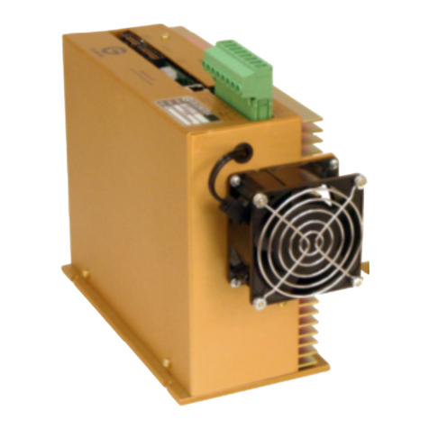
SMB9430 SPINDLE AMP UNDERGOING TESTING

Glentek Inc. 208 Standard Street, El Segundo, California 90245, U.S.A. (310) 322-30266
Alpha Series Digital PWM Spindle Manual
Overview
Glentek’s new High Speed Spindle Drives provide ultimate performance for your application. Ad-
vanced space vector algorithms and commutation techniques developed at Glentek provide sine wave
output from square wave Hall sensor input. This eliminates higher order harmonics resulting in lower
motor operating temperature and longer life.
By utilizing Field Oriented Control algorithms our drive can achieve speeds up to 100,000 RPM.
Typical applications include: Lens Grinding, Semiconductor Silicon Slicing, High Speed Die Grinding,
High Speed Routers, Semiconductor Wafer Processing, High Speed Nut Driving (automotive) and
many more.
Glentek’s High Speed Spindle Drives can work with any feedback device, including Sentron’s sine
wave Hall Sensors.
Brand-label opportunities are available. Please contact Jason Mark at 310-322-3026 ext 173
Examples of motors in successful applications using Glentek spindle amplifiers:
This manual guides the application engineer through the steps necessary for installation of the Alpha
series digital spindle amplifiers. All features of the Alpha series digital spindle amplifier are explained
and the procedures for installation and tuning are covered. The following sections are presented in an
order that will make installation easy for most first time users of the Alpha Series digital amplifiers.
The “Product Description” and “Features” sections provide the application engineers data for system
integration of the Alpha Series digital amplifiers.
Next, MotionMaestro
©
software is introduced. Enough material is given here to familiarize the
application engineer with the software tools necessary to setup, install and run a motor using the Alpha
series digital spindle amplifiers. For additional information refer to the MotionMaestro
Software Guide
at www.Glentek.com.
The application engineer is then guided through a step by step procedure for setting up and tuning a
digital spindle system.
Again, thank you and we look forward to providing you a product that will make your system perform at
its very best level.
MANUFACTURER MODEL #/ or PART #
Loadpoint Bearings Ltd. D03698
Loadpoint Bearings Ltd. 5716/1 LH
Loadpoint Bearings Ltd. D03604
Loadpoint Bearings Ltd. D03209
Westwind 50-06160-00
Westwind 50-0617-0

Glentek Inc. 208 Standard Street, El Segundo, California 90245, U.S.A. (310) 322-3026 7Glentek Inc. 208 Standard Street, El Segundo, California 90245, U.S.A. (310) 322-3026
Product Description
Glentek’s Alpha Series Digital PWM High Speed Spindle Amplifiers offer the latest in high performance
DSP control of both high speed spindle motors. With extensive utilization of surface mount technology
and special heat transfer techniques, the Alpha Series offers one of the world’s most powerful products
for a given form factor.
The Full Feature amplifier operates in current (torque) mode or velocity (RPM) mode, accepts a +/-10V
analog input as a command reference and commutates the motor sinusoidally for ultra smooth opera-
tion at low speeds. The amplifier utilizes an incremental encoder (or Hall signals) to derive the velocity
signal and to commutate the motor. The absolute commutation angle is usually determined using Hall
sensors or encoder commutation tracks. However, in some cost sensitive applications where slight
motor movement is acceptable upon power up, the amplifier can perform a power-on phase finding al-
gorithm which eliminates the need for Hall sensors or Commutation tracks. All modes of operation can
also be supported utilizing synchro resolver feedback instead of an encoder. It is best to consult
Glentek’s sales application group. Also, we can customize a serial port digital interface to adapt to
your controller as required to meet your protocols such as Ethernet, CAN, RS485, etc.
Current (Torque) Mode Servo Amplifier
The current mode spindle amplifier accepts a +/-10V analog input as a current command. For this
mode of operation, the amplifier provides high current loop bandwidth for high acceleration and high
speed spindle applications.
Velocity (RPM) Mode Servo Amplifier
The velocity mode spindle amplifier accepts a +/-10V analog input as a velocity command. For this
mode of operation, a digital velocity value is continuously calculated from the Hall or encoder input sig-
nals. Glentek’s high gain / high bandwidth velocity mode spindle amplifiers are preferred and utilized in
many very high performance spindle systems.
CANopen Servo Amplifier
The CANopen spindle amplifier incorporates all the features of the Full Feature spindle amplifier and
also accepts high speed serial digital command input. The digital command can be current command
if the amplifier is operating in Current Mode or velocity command if the amplifier is operating in Velocity
Mode. The CAN protocol is in compliance with CAN in Automation (CiA) DS-301 V4.02 standard. See
CANopen Installation and Operation Manual for more detail.
Production Description

Glentek Inc. 208 Standard Street, El Segundo, California 90245, U.S.A. (310) 322-30268
Alpha Series Digital PWM Spindle Manual
Features
• CE compliant: All servo amplifiers are CE marked.
• FOC: All Alpha Series employ Field Oriented Control method which al-
lows accurate control in both steady state or transient operation.
• Digital current loops: Current loop bandwidths up to 3 kHz.
• Digitally tuned: All parameters set digitally. No potentiometers to adjust. DSP
control for the ultimate in high performance.
• Silent operation: 25 kHz PWM standard.
• Wide operating voltage: All models can be ordered for operation from either 110-130 VAC
or 208-240 VAC (3-phase, 50/60 Hz)
Note: Non-standard voltages can be ordered on request.
• Stand alone operation: All models include internal DC power supply, cooling fans and a
regen clamp with dumping resistor. (Exception: SMC versions,
see next feature).
• External logic supply: SMC versions require an external 24 - 48VDC, (600 mA min)
power supply for amplifier logic, encoder or Hall sensors. This en-
ables “keep alive” ability.
• RS-232 or RS-485: High speed (115.2K baud) serial communication interface for (RS
-485 is optional) setup and tuning.
• CANopen: High speed (up to 1 Mb/s) serial communication interface for
communications between nodes in real-time control applications.
• Encoder feedback: Accepts nominal encoder signals 5 MHz (maximum frequency
of up to 10 MHz is possible, but is system dependent).
• Parametric filtering: Provides control engineers advanced filtering to eliminate un-
wanted system mechanical resonance.
• Sinusoidal commutation: For the ultimate in efficiency and smooth motion, Commutates
from almost any resolution linear or rotary encoder.
• Smart-Comm Initialization: Eliminates the need for Hall sensor or commutation tracks for
many applications.
• Auto Phase Finding: Plug and Play for all type of three phase brushless motors.
Provides control engineers ability to connect any motor leads to
any amplifier motor outputs. The amplifier’s smart algorithm will
automatically find and align the motor phases to allow for most
optimized smoothness and efficient commutation.
• Auto Phase Advance: Glentek’s advanced algorithms incorporated in the Alpha Series
drives, automatically provide phase advance, insuring that the
current is delivered at the appropriate time, provide the most
efficient operation.
• Space Vector Modulation: Glentek’s advanced algorithms allow for maximum utilization of
the DC BUS voltage while generating minimum harmonic distor-
tion of the currents in the winding of 3-phase AC motor.

Glentek Inc. 208 Standard Street, El Segundo, California 90245, U.S.A. (310) 322-3026 9Glentek Inc. 208 Standard Street, El Segundo, California 90245, U.S.A. (310) 322-3026
Features
• Software configurable: Glentek’s Windows™ based MotionMaestro
©
software provides
ease of set-up, monitoring and tuning with no previous program-
ming experience required. This software is Windows™
95/98/2000/XP, NT, Vista, and 7 compatible.
• Non-volatile memory: All parameters are stored in non-volatile memory
for reliable start up. In addition, up to two different configurations
can be stored in the amplifier’s non-volatile memory.
• Dedicated inputs: Go/Stop, E-Stop, inhibit, fault , motor over temp, reset signal, and
+/- 10V analog input.
• Dedicated outputs: Selectable analog monitor signal, fault and encoder output.
• Relay outputs: These two pins provide an interface for the relay. They turn on .
(Optional) when desired condition occurred.
• Complete isolation: Complete optical isolation between signal and power stage.
• Fault protection: Short from output to output, short from output to ground, amplfier
RMS over current, amplifier under/over voltage, amplifier over
temperature, motor over temperature.
• Status indicator: 7-segment display indicates amplifier status and diagnostics.
• SMT construction: Provides ultra compact size, cost competitive package and high
reliability.

Glentek Inc. 208 Standard Street, El Segundo, California 90245, U.S.A. (310) 322-302610
Alpha Series Digital PWM Spindle Manual
Standard Operating Conditions
Temperature
Min. = 0º C
Max. = 60º C
Humidity Range
5-95% Non-condensing
Altitude
This amplifier is rated for up to 1000m, above which performance may deteriorate.
Shock
Do not expose the amplifier to sudden shock (dropping, shaking, etc…)
Vibration
Do not install the amplifier in an area prone to constant vibration.
Electromagnetic Interference
Do not install the amplifier near sources of EMI
Atmospheric Pollutants
Do not install the amplifier in an environment where the atmosphere contains pollutants
such as dust, corrosives, etc...
Water
Keep the amplifier away from all water hazards, including pipes that may accumulate
condensation and areas that can become excessively humid.
Overheating
Ensure that the amplifier’s air vents are not obstructed. Allow a clearance of 75mm
(minimum) above the amplifier for proper ventilation.

Glentek Inc. 208 Standard Street, El Segundo, California 90245, U.S.A. (310) 322-3026 11Glentek Inc. 208 Standard Street, El Segundo, California 90245, U.S.A. (310) 322-3026
Control Block Diagrams
Control
Block
Diagrams

Glentek Inc. 208 Standard Street, El Segundo, California 90245, U.S.A. (310) 322-302612
Alpha Series Digital PWM Spindle Manual

Glentek Inc. 208 Standard Street, El Segundo, California 90245, U.S.A. (310) 322-3026 13Glentek Inc. 208 Standard Street, El Segundo, California 90245, U.S.A. (310) 322-3026
Velocity Control Loop Diagram
Gain
Velocity
Command
Integer
Settable
(GVC)
Gain Velocity
Scale in Counts
per Interrupt
Power of 2
settable
2
0
=1
2
8
=256
(GVS)
Mode 2
Velocity
Command
(SVC)
View MM
Low Pass
Feedback filter
+
-
+
+
Velocity Control Loop Diagram Alpha Series
Velocity
Error
MM Set
+
+
MM Set
MM Set
Raw Velocity
Estimate
∑
∑∑
∑
Proportional
Gain
MM Set
32768
)GVP(
Integral Gain
MM Set
32768
)GVI(
∑
∑∑
∑
∑
∑∑
∑
Tach Gain
MM Set
32768
)GVF(
Derivative Gain
MM Set
256
)GVD(
Scaled Velocity
MM View
)SVS(
±32767
Mode 2
Velocity Loop
Error Command
to Current Loop
(SVC)
Velocity
From Current
Control Loop
Diagram
Measured Motor
Velocity with Lead
and Gain

Glentek Inc. 208 Standard Street, El Segundo, California 90245, U.S.A. (310) 322-302614
Alpha Series Digital PWM Spindle Manual

Glentek Inc. 208 Standard Street, El Segundo, California 90245, U.S.A. (310) 322-3026 15Glentek Inc. 208 Standard Street, El Segundo, California 90245, U.S.A. (310) 322-3026
Software
Amplifier Setup Software
MotionMaestro
is Glentek's Windows based application software that was designed to communicate
with the Alpha series digital amplifiers. MotionMaestrohas many dialogs with values shown in engi-
neering units to make it easy to select and setup the features of the amplifier. MotionMaestro
utilizes
the standard binary command set and protocols. Although it is not necessary to use MotionMaestro
,
installation, setup and tuning is made easier through its use. For more information please refer to the
MotionMaestro
Software Guide at www.Glentek.com.
MotionMaestro
has many features that allow application engineers to easily configure a digital amp to
an application. It has a terminal mode that operates at 115k baud transmission rates, an oscilloscope
that can be used to monitor amplifier signals and a tuning dialog that can be used to control the motor
input. By using the oscilloscope and tuning dialog, one can monitor step response to determine filter
parameters for optimal control loop performance.
Glentek developed a Communication Module CM998-1 to provide Ethernet communication between
the Host computer that is running MotionMaestro
and the amplifier. The Host computer communi-
cates with the CM998-1 by Ethernet, and the CM998-1 communicates with the amplifier by RS-232 or
RS485 (you must have the proper serial cable wired as described in the Amplifier Connection Interface
section of this manual). The CM998-1 is plug-and-play, and there is no special setup required. Please
contact one of Glentek’s sale engineers for further details.
MotionMaestro
Installation
MotionMaestro
requires Windows95, Windows 98 SE, Windows ME, Windows NT 4.0, Windows
2000, Windows XP, Windows Vista or Windows 7 operating system running on a PC with at least one
serial port. It is suggested that you have no less than 3 megabytes of application program disk space
remaining on the hard drive prior to installation. The MotionMaestro
install disk is setup to utilize In-
stall Shield to simplify installation. There are only a few setup options offered. In general you can
press NEXT or YES until installation is complete. When installation is completed, you will find a Mo-
tionMaestro
shortcut on the windows Start\Programs menu.
DO NOT RUN MOTIONMAESTROUNTIL YOU HAVE READ ALL OF THIS SECTION.
The MotionMaestro
installation program is named Setup.exe. It is found in the MotionMaestro
\disk1 directory of the distribution CD. The installation will create a Glentek folder in the Program Files
folder. A MotionMaestro
_X_X folder is created where _X_X matches the version number. You can
have multiple versions of MotionMaestro
installed, if you wish, and they will be placed into their own
directories.

Glentek Inc. 208 Standard Street, El Segundo, California 90245, U.S.A. (310) 322-302616
Alpha Series Digital PWM Spindle Manual
MotionMaestro
amplifier setup features.
This section of this manual is an introduction to MotionMaestro’s
features that are required for instal-
lation and setup of the Alpha series amplifiers. Only those features of MotionMaestro
required for de-
fining motor characteristics are covered. This is not meant to be a step by step tutorial. The
“Connecting the Amplifier to the motor” section is intended as a tutorial for motor setup. You may need
to refer to this section when setting up a motor. The following features are reviewed here.
1. Opening of communications.
2. Model Information.
3. Digital I/O setup.
4. Mode setup.
5. Motor Parameters.
6. Motor Safety.
7. Commutation Setup.
8. Gearing/Encoders Setup.
9. Trajectory Generator.
10. Filters.
11. Analog I/O setup.
12. Oscilloscope.
13. Terminal Window.
14. Amplifier Status.
15. Control Panel.
16. Motor Tuning.
17. Saving parameters.
18. Backing up a copy of amplifier parameters.
Opening of communications
Before MotionMaestrocan be used, communications must be established between the amplifier and
the PC that MotionMaestrois running on. Before opening communications in MotionMaestro,you
must decide what communication method between the Host computer and amplfier is used (RS-232
only, Ethernet to RS-232 or Ethernet to RS-485 using Communication Module CM998-1) and have a
serial communications cable wired as described in the Amplifier Connection Interface section of this
manual.
When MotionMaestro
is directed to establish communications with the amplifier, the amplifier is que-
ried for a model ID and Firmware version. MotionMaestrowill configure itself and select the appropri-
ate configuration files based on the amplifier returned values.
There are extensive help screens under the Help menu. Select Help Topics and you can read about
the usage of MotionMaestro
and it’s features.
Open communications by selecting the “Open” option on MotionMaestro’smain menu tool bar.
Open - To make connection with an amplifier

Glentek Inc. 208 Standard Street, El Segundo, California 90245, U.S.A. (310) 322-3026 17Glentek Inc. 208 Standard Street, El Segundo, California 90245, U.S.A. (310) 322-3026
Software
Depending on which communication method between the Host computer and amplifier is used, one of
the following two screens for establishing communication link would be opened.
If the communication method is by RS-232 between the
Host computer and amplifier, the “Open Communica-
tions” window is displayed.
Select the COM port that you connected the serial port
cable to and ensure that a baud rate of 115200 is se-
lected. Click and select the check box next to Alpha Se-
ries (to distinguish from Omega Series protocol). When
you press OK, MotionMaestro
will query the amplifier to
determine what amplifier model is connected.
If communications is established, you should see a screen
similar to the “MotionMaestro’s main window using RS232”
with all green communications status indicators.
If the communication method is by Ethernet to RS-
232 or Ethernet to RS-485 using Communication
Module CM998-1 between the Host computer and
amplifier, the “Select Communications Link” window
is displayed.
Click and select the check box next to Alpha Series
(to distinguish from Omega Series protocol). Click
to highlight “GtkNet Module”, and click on “Open
Link”. When you press OK, MotionMaestro
will
query the amplifier to determine what amplifier
model is connected.
If communications is established, you should see a screen
similar to the “MotionMaestro’s main window using
Ethernet” with all green communications status indicators.
Open Communications dialog box using Ethernet be-
tween Host computer to amplifier via Communication
Module CM998-1
Open Communications dialog box using
RS-232 between Host computer to amplifier
MotionMaestro’s main window using RS-
MotionMaestro’s main window using

Glentek Inc. 208 Standard Street, El Segundo, California 90245, U.S.A. (310) 322-302618
Alpha Series Digital PWM Spindle Manual
Below, MotionMaestro’s main window is shown where communications are successfully opened and
various setup and monitoring screens are activated. These active screens do not necessarily need to
remain within MotionMaestro’s main window, they may reside anywhere on the Windows desktop.
Model Information
For informational purposes, you can refer to the Model Info dialog
to view the design features and limits of the particular amplifier.
To view this dialog, you must select the “Tools” option on Motion-
Maestro’s
main menu tool bar, then select “Model Info”.
Here you will be able to view your firmware version, amp model
number, power board number and logic board number.
In addition, MotionMaestro’s Model Info dialog window will dis-
play amplifier settings. For example, on the left these settings
are current balance offsets, current feedback, continuous current
and peak current settings. These settings, in addition to the Bus
under-voltage and over-voltage settings, are useful informational
tools and are required if the user performs his own scaling of am-
plifier values.
Model Info Box
MotionMaestro’s Sever activated windows

Glentek Inc. 208 Standard Street, El Segundo, California 90245, U.S.A. (310) 322-3026 19Glentek Inc. 208 Standard Street, El Segundo, California 90245, U.S.A. (310) 322-3026
Software
Digital I/O setup
The Digital I/O settings can be used to tailor the
amplifier digital signal inputs to the requirements
of your application. Failure to properly setup the
Digital I/O signals may result in the amplifier
powering up in a fault condition. (Or worse yet a
reset condition). To view this dialog, select the
“Setup” option on MotionMaestro’s
main menu
tool bar, then select “Digital IO...”. Digital I/O
signals can be active high or active low depend-
ing on the applications. The Motor Over Heated
condition is a good example. From this window
you can modify what state the amplifier consid-
ers to be a Motor Over Heated fault condition,
either high or low.
On this window there are two sets of check-
boxes, for each signal, Wkg and Amp. Amp
displays the current amp setting while Wkg dis-
plays the users choice. The amp is automati-
cally updated as the Wkg box changes.
Amplifier Mode setup
The full featured amplifier can operate in either current or velocity
mode. By selecting the “Setup Mode...” item on the “Setup” option
menu, you can configure the amplifier to operate in desired mode.
MotionMaestro
uses the Mode setting to determine text and op-
tions on many of the dialog display windows. For example, when
the Alpha series amplifiers are in current mode, parameters on the
Tuning dialog pertaining to the velocity loop are not available.
Engineering unit scaling used internally by MotionMaestro
is also
adjusted to reflect proper units based on mode.
Motor Safety setup
Motor safety is where limits to protect the motor are
entered. The “Motor Safety Setup” dialog is avail-
able from the “Setup” menu. There are two sets of
boxes, one labeled Working, the other Amplifier.
Amplifier displays the current amp setting while
Working displays the users selection. Here you can
setup a maximum current limit, and low speed Motor
safety is where limits to protect the motor are en-
tered. In order to update the motor parameters in
the amplifier, the amp must be disabled. You can do
this by clicking on the “Disable/Enable Amp” button
first, then the “Send Values To Amp” button. Press-
ing F1 displays the dialogs help text. After the val-
ues are sent to the amp, you may test the values by
enabling the amplifier.
Dialog box for setting digital I/O active level
Dialog box for setting amplifier mode
Dialog box for setting up motor safety parameters

Glentek Inc. 208 Standard Street, El Segundo, California 90245, U.S.A. (310) 322-302620
Alpha Series Digital PWM Spindle Manual
Motor Parameters Setup
Note: Glentek recommends that you use the “Setup
Motor Parameters” tuning, and only use the “Setup
Auto/Manual Current Loop Tuning” window when
you want some preliminary values to start with.
Select “Motor Parameters” on the “Setup” menu to acti-
vate the Motor Parameters dialog. The Motor Parame-
ters dialog is used to set digital current loop gains. Mo-
tionMaestro
will calculate current loop gains based on
the values entered. Select “Motor Parameters” on the
“Setup” menu to activate this dialog.
Motor Resistance and Inductance are entered as phase
to phase values. If these values are not indicated on
the motor label, you can determine these values by
measuring the resistance or inductance between two
motor wires connecting two phases of the motor. Nomi-
nal DC bus voltage is the regulated bus voltage, 160 or
320 volts typically. Current loop bandwidth is a meas-
ure of the current loops responsiveness. Generally you want this to be as high as possible. A good
starting point is 1500 Hz. In order to update the motor parameters in the amplifier, the amp must be
disabled. You can do this by clicking on the “Disable/Enable Amp” button first then the “Send Values
To Amp” button. Pressing F1 displays the dialogs help text.
Auto/Manual Current Loop Tuning Setup
Select “Setup Auto/Manual Current Loop Tuning” button
on the “Setup Motor Parameters” window to activate this
dialog.
Motor Resistance, Inductance, and Nominal DC Buss
voltage can be entered here if not already done so in
the “Setup Motor Parameters” window. 1-Phase is se-
lected when amplifier drives brush type DC motor or
voice coil motor. 3-Phase is selected when amplifier
drives 3 phase brushless motor.
There are two tuning methods that a user can choose.
The auto tuning method is used to generate some pre-
liminary values. In order to activate this method, Auto
Tuning and motor type boxes are checked, then Calcu-
late Auto Tuning button is depressed. The Proportional,
Integral, Derivative, Master gains, and Effective Band-
with values are automatically calculated and optimized.
You may also opt to use manual tuning method where
the gains can be altered. In this mode, the Manual Tun-
ing and motor type boxes are checked. Then all current
loop gains may be adjusted and the new values send to
the amplifier while viewing the current loop response
with an oscilloscope or running a bode plot. For manual
tuning setup information, refer to Current (Torque) Mode
Tuning section of this manual.
Dialog box for entering motor parameters
Dialog box for entering motor and
current loop auto/manual tuning
parameters
Other manuals for Alpha Series
1
This manual suits for next models
4
Table of contents
Other Glentek Amplifier manuals

Glentek
Glentek SMA8730 Installation and operating instructions

Glentek
Glentek GA369 Installation and operating instructions

Glentek
Glentek SMA8130 Installation and operating instructions

Glentek
Glentek Omega SMC9930 User manual

Glentek
Glentek SMA7130 Installation and operating instructions

Glentek
Glentek GA4571PR2 Installation and operating instructions

Glentek
Glentek Omega Series User manual

Glentek
Glentek SMA7105 Installation and operating instructions

Glentek
Glentek SMA8115 Installation and operating instructions

Glentek
Glentek SMA5005 Installation and operating instructions