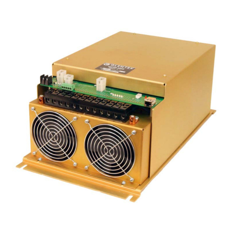
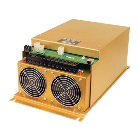
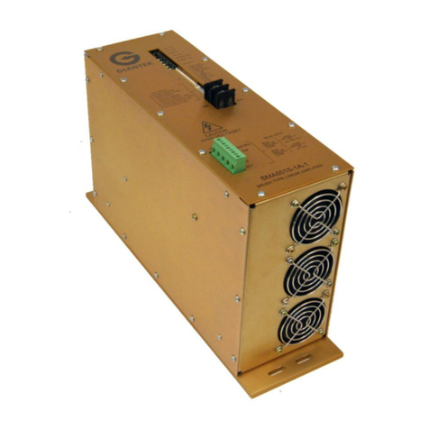
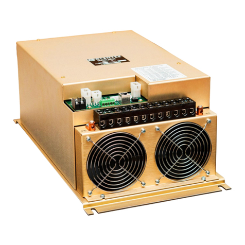
Glentek Gamma Series User manual

INSTALLATION & OPERATION MANUAL
Gamma Series
Digital - High Bandwidth
PWM Brush and Brushless Servo Drives
SMB/SMC 9G16
Congratulations, You Cared
Enough to Buy the Very Best!
Manual Revision Date:
27 January 2021

Revision History
Page
Rev
Description
ECO
Date
Changes
APPD
A
Initial Release
4295
5NOV20
D.C.R.
L.P.
118
A1
Corrected status display codes table
4295
27JAN21
D.C.R.
L.P.

Gamma Series Digital PWM Drive Manual VIEW TABLE OF CONTENTS
208 Standard Street, El Segundo, California 90245, (310) 322-3026 3
TABLE OF CONTENTS
TABLE OF CONTENTS .................................................................................................................................... 3
TABLES............................................................................................................................................................. 6
FIGURES ........................................................................................................................................................... 7
1. OVERVIEW....................................................................................................................................................8
2. PRODUCT DESCRIPTION............................................................................................................................9
2.1 FEATURES................................................................................................................................................11
Performance....................................................................................................................................11
Regulatory.......................................................................................................................................13
Connectivity.....................................................................................................................................13
Feedback ........................................................................................................................................13
I/O....................................................................................................................................................13
Input ................................................................................................................................................13
Build ................................................................................................................................................14
2.2 ENVIRONMENTAL CONDITIONS...................................................................................................................15
2.3 SMX9G16 RATINGS,SPECIFICATIONS AND NUMBERING.............................................................................16
2.4 PACKAGE CONFIGURATIONS AND DIMENSIONS...........................................................................................19
2.5 SMX9G16 STAND ALONE MODEL NUMBERING ..........................................................................................21
2.6 SMX9G16 MODULE MODEL NUMBERING...................................................................................................22
2.7 SMX9G16 MULTI-AXIS MODEL NUMBERING ..............................................................................................23
3. DRIVE INTERFACE AND WIRING .............................................................................................................24
3.1 CONTROLLER I/O......................................................................................................................................24
Programmable Digital Inputs...........................................................................................................26
Programmable Digital Outputs........................................................................................................31
Analog Inputs ..................................................................................................................................34
Analog Outputs ...............................................................................................................................36
Encoder Outputs .............................................................................................................................38
Programmable Digital Input Functions............................................................................................39
Programmable Digital Output Functions.........................................................................................40
3.2 BRAKE/STO CONNECTOR.........................................................................................................................42
Logic Power Inputs..........................................................................................................................43
Brake Output...................................................................................................................................44
STO Inputs......................................................................................................................................45
3.3 COMMUNICATION INTERFACE.....................................................................................................................46
Servo Drive Serial Communications Connector .............................................................................46
RS-232............................................................................................................................................47
CANopen Interface..........................................................................................................................48
3.4 MOTOR FEEDBACK CONNECTOR AND WIRING............................................................................................50
Tachometer.....................................................................................................................................53
Resolver..........................................................................................................................................54
Sin/Cos Encoder .............................................................................................................................55
3.5 SERVO DRIVE MOTOR AND POWER CONNECTORS .....................................................................................56
4. DRIVE SETUP .............................................................................................................................................61
4.1 USING MOTIONMAESTRO TO SETUP A BRUSHLESS MOTOR ........................................................................61
4.2 CURRENT (TORQUE)MODE.......................................................................................................................64
Signal Gain......................................................................................................................................64
Tach. Reverse.................................................................................................................................64
Signal Offset....................................................................................................................................65
Dead Band ......................................................................................................................................66
Current Mode Brake Operation.......................................................................................................67
4.3 VELOCITY (RPM) MODE TUNING...............................................................................................................68
GVS (Gain Velocity Scale) Setting..................................................................................................68
Velocity Loop PID Setting ...............................................................................................................68
Velocity Mode Brake Operation ......................................................................................................70

Gamma Series Digital PWM Drive Manual VIEW TABLE OF CONTENTS
4 Glentek: Solutions for Motion Control
4.4 POSITION MODE .......................................................................................................................................73
Pulse Follower Position Mode Tuning.............................................................................................73
Configure Pulse and Direction Follower Mode................................................................................75
Configure Encoder Quadrature A/B (Encoder Follower) Mode.......................................................77
Configure CW and CCW Pulse Follower Mode ..............................................................................79
4.5 TWO PHASE CURRENT MODE TUNING........................................................................................................80
Preliminary Setup............................................................................................................................80
Setup Motor.....................................................................................................................................80
Configure Command Signal Inputs .................................................................................................81
Drive Running..................................................................................................................................81
4.6 TACHOMETER FEEDBACK DEDICATED DRIVE..............................................................................................82
4.7 FINE TUNING (MANUAL TUNING)................................................................................................................83
5. MOTIONMAESTRO© ..................................................................................................................................84
5.1 IMPORTANT INFORMATION BEFORE STARTING............................................................................................84
5.2 INSTALLING MOTIONMAESTRO...................................................................................................................84
5.3 CONVENTIONS USED IN THIS MANUAL.........................................................................................................85
5.4 MOTIONMAESTRO OVERVIEW....................................................................................................................86
Main Menu and Toolbar ..................................................................................................................86
5.5 COMMUNICATIONS ....................................................................................................................................89
5.6 MOTOR PARAMETERS ...............................................................................................................................91
5.7 MOTOR SAFETY........................................................................................................................................92
5.8 COMMUTATION .........................................................................................................................................94
5.9 COMMUTATION CONFIG TAB......................................................................................................................96
Initialization Method (Visible for all motor and feedback types)......................................................96
Selection of a Commutation Initialization Method...........................................................................97
Brushless Configuration..................................................................................................................97
Phase Lead .....................................................................................................................................97
Correction Method...........................................................................................................................98
Smart Commutation ........................................................................................................................98
Simulated Hall .................................................................................................................................99
Auto-Phase......................................................................................................................................99
5.10 DRIVE MODE ........................................................................................................................................100
5.11 FEEDBACK CONFIG TAB ........................................................................................................................101
Encoder Data ..............................................................................................................................101
Sin/Cos Interpolation...................................................................................................................101
Analog Motor Feedback Calibration............................................................................................102
Tachometer Data.........................................................................................................................102
5.12 SETUP DIGITAL INPUTS .........................................................................................................................103
5.13 SETUP DIGITAL OUTPUTS......................................................................................................................104
5.14 FILTERS ...............................................................................................................................................106
5.15 PROFILE GENERATOR...........................................................................................................................108
5.16 OSCILLOSCOPE.....................................................................................................................................112
Adding Scope Channels..............................................................................................................113
Oscilloscope Channels Settings..................................................................................................114
Channel List ................................................................................................................................115
Channel Source Section..............................................................................................................116
6. REFERENCE INFORMATION...................................................................................................................117
6.1 ON BOARD STATUS DISPLAY...................................................................................................................118
6.2 MATCHING BRUSHLESS MOTOR PHASE LEADS TO MOTOR FEEDBACK.......................................................119
Verify Motor Phasing and Alignment.............................................................................................120
Adjusting Alignment.......................................................................................................................123
Manual Phasing Procedure...........................................................................................................124
Auto Phasing Procedure ...............................................................................................................128
6.3 DETERMINING ENCODER SPECS AND NUMBER OF MOTOR POLES ............................................................131
Encoder Resolution.......................................................................................................................131
Encoder Reverse...........................................................................................................................131
Encoder Outputs ...........................................................................................................................131
Number of Poles (Note: Requires Hall sensors)...........................................................................132

Gamma Series Digital PWM Drive Manual VIEW TABLE OF CONTENTS
208 Standard Street, El Segundo, California 90245, (310) 322-3026 5
6.4 REPLACEMENT FOR ALPHA SERIES DRIVES..............................................................................................133
6.5 DRIVE TERMS AND TECHNOLOGY ............................................................................................................134
Terms............................................................................................................................................134
Technology....................................................................................................................................136
6.6 CONTROL BLOCK DIAGRAMS...................................................................................................................138
Position Mode Control Diagram ....................................................................................................139
Command Input Control Diagram .................................................................................................140
Velocity Control Loop Diagram .....................................................................................................141
Current Control Loop Diagram......................................................................................................142
6.7 DIMENSIONS...........................................................................................................................................143
(Non-UL) SMB/SMC9G16-1A/1B Standalone Short Fin...............................................................144
(UL) SMB/SMC9G16-1A/1B Standalone Short Fin ......................................................................145
(Non-UL) SMB/SMC9G16 Standalone Long Fin..........................................................................146
(UL) SMB/SMC9G16 Standalone Long Fin..................................................................................147
(Non-UL) SMB/SMC9G16-1 Module L-Bracket............................................................................148
(UL) SMB/SMC9G16-1 Module L-Bracket....................................................................................149
(Non-UL) SMB/SMC9G16-1 Module Short Fin............................................................................150
(UL) SMB/SMC9G16-1 Module Short Fin.....................................................................................151
(Non-UL) SMB/SMC9G16-1 Module Long Fin .............................................................................152
(UL) SMB/SMC9G16-1 Module Long Fin ...................................................................................153
(Non-UL) SMB/SMC9G16 2-Axis Package: L-Bracket or Short Fin Modules ............................154
(UL) SMB/SMC9G16 2-Axis Package: L-Bracket or Short Fin Modules...................................155
(Non-UL) SMB/SMC9G16 2-Axis Package: Long Fin Fin Modules............................................156
(UL) SMB/SMC9G16 2-Axis Package: Long Fin Modules..........................................................157
(Non-UL) SMB/SMC9G16 4-Axis Package: L-Bracket or Short Fin Modules ...........................158
(UL) SMB/SMC9G16 4-Axis Package: L-Bracket or Short Fin Modules...................................159
(Non-UL) SMB/SMC9G16 5-Axis Package: L-Bracket or Short Fin Modules ...........................160
(UL) SMB/SMC9G16 5-Axis Package: L-Bracket or Short Fin Modules...................................161
6.8 FACTORY REPAIR,MAINTENANCE AND WARRANTY...................................................................................162
Factory Repair...............................................................................................................................162
Maintenance..................................................................................................................................162
Warranty........................................................................................................................................163
6.9 EUROPEAN UNION EMC DIRECTIVES.......................................................................................................164
Electromagnetic Compatibility Guidelines For Machine Design ...................................................164
Filtering..........................................................................................................................................165
AC Line Filter Selection.................................................................................................................165
Grounding .....................................................................................................................................167
Shielding and Segregation............................................................................................................168
European Union Declaration of Incorporation Motion Control Systems .......................................170

Gamma Series Digital PWM Drive Manual VIEW TABLE OF CONTENTS
6 Glentek: Solutions for Motion Control
Tables
Table 2-1 –Product Features........................................................................................................10
Table 2-2 –Environmental Conditions...........................................................................................15
Table 2-3 –Electrical Ratings........................................................................................................17
Table 2-4 –Stand Alone Dimensions.............................................................................................19
Table 2-5 –Module Dimensions ....................................................................................................20
Table 2-6 –Multi-Axis Dimensions.................................................................................................20
Table 3-1 –Controller I/O Configuration ........................................................................................25
Table 3-2 –Optically Isolated Input Specs.....................................................................................26
Table 3-3 –Schmitt Trigger Input Specs........................................................................................27
Table 3-4 –Differential Digital Input Specs....................................................................................28
Table 3-5 –MOSFET Output Specs..............................................................................................31
Table 3-6 –Optically Isolated Output Specs..................................................................................32
Table 3-7 –Relay Output Specs....................................................................................................33
Table 3-8 –Analog Input Specs.....................................................................................................34
Table 3-9 –Analog Output Specs..................................................................................................36
Table 3-10 –Analog Output Function List......................................................................................37
Table 3-11 –Programmable Digital Input Functions ......................................................................39
Table 3-12 –Programmable Digital Output Functions (Faults).......................................................40
Table 3-13 –Programmable Digital Output Functions (Status) ......................................................41
Table 3-14 –Brake/STO Connector Pin Function..........................................................................43
Table 3-15 –Logic Power Specs...................................................................................................43
Table 3-3-16 –Brake Output Specs...............................................................................................44
Table 3-17 –STO Inputs ...............................................................................................................45
Table 3-18 –RJ45 Mating Connector............................................................................................46
Table 3-19 –RJ45 (RS-232 Communication Designations)...........................................................46
Table 3-20 –Serial Speed over Distance.......................................................................................48
Table 3-21 –RJ45 (CANopen) Communication Designations........................................................48
Table 3-22 –Motor Feedback Designations: TTL Encoder/Hall Communication............................50
Table 3-23 –Motor Feedback Specs.............................................................................................51
Table 3-24 –Digital Hall Sensor Specs .........................................................................................51
Table 3-25 –Tachometer Sensor Specs........................................................................................53
Table 3-26 –Motor Feedback Designations: Resolver...................................................................54
Table 3-27 –Motor Feedback Designations: Sin/Cos & Absolute Encoder...................................55
Table 3-28 –UL and Non-UL Stand Alone Motor Output Designations –3 Pin..............................56
Table 3-29 –UL and Non-UL Stand Alone AC Power Input Designation –4 Pin ...........................57
Table 3-30 –UL and Non-UL Module DC Power Input and Motor Output Designation –5 Pin ......59
Table 5-1 –MotionMaestro Menu Options.....................................................................................87
Table 5-2 –Motor Parameter Field Information..............................................................................91
Table 5-3 –Motor Safety...............................................................................................................93
Table 5-4 –Commutation Initialization Methods ............................................................................96
Table 5-5 –Filter Parameters......................................................................................................107
Table 5-6 Control Type/Mode......................................................................................................109
Table 5-7 –Actions......................................................................................................................109
Table 5-8 –Action Triggers..........................................................................................................110
Table 5-9 –Truth Table for Profile Address Selector (PAS) Pins.................................................111
Table 6-1 –Status Display Codes................................................................................................118

Gamma Series Digital PWM Drive Manual VIEW TABLE OF CONTENTS
208 Standard Street, El Segundo, California 90245, (310) 322-3026 7
Figures
Figure 3-1 44-Pin I/O connector....................................................................................................24
Figure 3-2 Optically Isolated Programmable Digital Input..............................................................26
Figure 3-3 Schmitt Trigger Digital Input.........................................................................................27
Figure 3-4 Differential Digital Input................................................................................................28
Figure 3-5 Differential Digital Input Single Ended..........................................................................29
Figure 3-6 Motor Over Temperature Input.....................................................................................30
Figure 3-7 MOSFET output...........................................................................................................31
Figure 3-8 Optically Isolated Programmable Digital Output...........................................................32
Figure 3-9 Relay Output................................................................................................................33
Figure 3-10 Differential Analog Input.............................................................................................34
Figure 3-11 Single Ended Analog Input.........................................................................................35
Figure 3-12 Analog Outputs..........................................................................................................36
Figure 3-13 Encoder Outputs........................................................................................................38
Figure 3-14 Logic Power/Brake Connector (Standard)..................................................................42
Figure 3-15 Logic Power/Brake/STO Connector (Optional)...........................................................42
Figure 3-16 Brake/Stop Sequence Internal Circuit ........................................................................44
Figure 3-17 STO Input Circuit .......................................................................................................45
Figure 3-18 RJ45 Mating Connector .............................................................................................46
Figure 3-19 RS-232 Chip Information............................................................................................47
Figure 3-20 RJ45 Double Mating Connector.................................................................................49
Figure 3-21 CANopen Connection Diagram..................................................................................49
Figure 3-22 Motor Feedback Connector........................................................................................50
Figure 3-23 Digital Hall Circuit (Differential) ..................................................................................51
Figure 3-24 Digital Hall Circuit (Single Ended) ..............................................................................52
Figure 3-25 Tachometer Circuit.....................................................................................................53
Figure 3-26 Resolver Circuit..........................................................................................................54
Figure 3-27 Sin/Cos Encoder Circuit.............................................................................................55
Figure 3-28 UL Stand Alone Motor Output Connector...................................................................56
Figure 3-29 Non-UL Stand Alone Motor Output Connector ...........................................................56
Figure 3-30 UL and Non-UL Stand Alone Motor Output Brushless................................................57
Figure 3-31 UL and Non-UL Stand Alone Motor Output Brush Type.............................................57
Figure 3-32 UL Stand Alone AC Power Input Connector...............................................................58
Figure 3-33 Non-UL Stand Alone AC Power Input Connector.......................................................58
Figure 3-34 UL and Non-UL Stand Alone AC Power Input............................................................59
Figure 3-35 UL Module DC Power Input and Motor Output Connector..........................................59
Figure 3-36 Non-UL Module DC Power Input and Motor Output Connector..................................60
Figure 3-37 UL and Non-UL Module DC Power Input and Motor Output.......................................60
Figure 4-1 Oscilloscope Waveforms..............................................................................................69
Figure 4-2 Brake/Stop Sequence If Zero Speed Window is Reached............................................72
Figure 4-3 Brake/Stop Sequence If Maximum Deceleration Time is Reached...............................72
Figure 6-1 Glentek Standard Commutated Encoder Signals.......................................................131
Figure 6-2 EMI Source-Victim Model...........................................................................................164
Figure 6-3 Single Point Ground Types ........................................................................................167

Gamma Series Digital PWM Drive Manual VIEW TABLE OF CONTENTS
8 Glentek: Solutions for Motion Control
1. Overview
This manual guides you through the steps necessary for the installation of Gamma Series Digital PWM
Servo Drives.
In this manual, all the features of the Gamma Series are explained. Also, it covers the procedures for
installation and tuning. The following sections are presented in an order that will make installation easy
for first time users of Gamma Series Drives.
The Product Description and Features sections provide you with the necessary information for system
integration of Gamma Series Drives.
You are then guided through a step by step procedure for the setup and tuning of a digital servo
system.
Next, Glentek’s MotionMaestro software is introduced. Enough material is given here to familiarize you
with the software tools to setup, install, and run a motor using a Gamma Series Drives. For additional
information, refer to the MotionMaestro Software Guide at www.glentek.com. As always, Glentek
application engineers are available to help you with your specific application goals. If you have any
questions at all, please contact us and we will help in any way we can.
Again, thank you and we look forward to providing you with a product that will make your system
perform at its very best.

Gamma Series Digital PWM Drive Manual VIEW TABLE OF CONTENTS
208 Standard Street, El Segundo, California 90245, (310) 322-3026 9
2. Product Description
The Gamma Series is Glentek’s latest offering of higher performance multi-core DSP control of
brushless (standard servo and high-speed spindle), brush type, rotary, linear, voice coil, and AC
induction motors. This drive offers expanded command and control modes including CANopen and
indexing/point-to-point. Gamma Series Drives also accept feedback from a wider range of devices and
protocols, namely absolute serial encoders (BiSS, EnDat and SSI) and analog Sin/Cos encoders.
Additional programmable I/O includes 5 optically isolated inputs, 6 Schmitt triggers, 2 differential inputs,
3 MOSFETS outputs, 2 optically isolated programmable outputs, and a general-purpose relay. AC
powered (stand alone and multi-axis) and DC powered (module) packages are available. These drives
incorporate Field Oriented Control (FOC) and Space Vector Modulation (SVM) algorithms, which
provide optimum control that enable motors to run cooler and at higher velocities. Set-up, tuning, and
system diagnostics are accomplished using MotionMaestro (Glentek’s Windows-based software).
Glentek can customize a serial port digital interface to adapt to your controller as required to meet your
protocols, such as Ethernet, CAN, RS485, etc.
The following table is a list of general specifications.

Gamma Series Digital PWM Drive Manual VIEW TABLE OF CONTENTS
10 Glentek: Solutions for Motion Control
Table 2-1 –Product Features
Command/Control Modes
+/-10 VDC for current (torque) or velocity (RPM)
Pulse (step) and direction
Encoder follower
CW/CCW (up/down mode)
External sine commutation (2-phase current mode)
RS-232 & RS-485
PWM for current (torque) or velocity (RPM) in 50% duty cycle format (one-wire) or
100% duty cycle format (two-wire)
Indexer/Point-to-Point
Camming/Gearing
CANopen
Ethernet
Feedback
Incremental quadrature encoder
Digital Hall sensors or commutation tracks from encoder
Absolute serial encoder (Biss, EnDat and SSI)
Analog Sin/Cos encoder
Resolver
Analog tachometer
I/O
Dedicated Digital I/O
Inputs: 2 STO optically isolated
Outputs: STO optically isolated indicator,
brake (max 2 A @ 24 VDC)
Programmable Digital I/O
Inputs: 5 optically isolated, 6 Schmitt trigger,
2 differential
Outputs: 3 MOSFETS (max 1.5 A, 24 VDC),
2 optically isolated (max 10 mA, 24 VDC),
relay (max 2 A, 30 VDC)
Analog I/O
Inputs: 2 differential (16-bit A/D)
Outputs: 2 Single Ended, Programmable (12-bit A/D)
Safety Disable
Safe Torque Off (STO) in accordance with IEC61800-5-2

Gamma Series Digital PWM Drive Manual VIEW TABLE OF CONTENTS
208 Standard Street, El Segundo, California 90245, (310) 322-3026 11
2.1 Features
Performance
Field Oriented Control: All Gamma Series Drives employ a Field Oriented Control (FOC)
method, which allows accurate control in both steady state or
transient operation and optimal orientation of the magnetic field in a
motor.
Space Vector Modulation: Glentek’s advanced algorithms allow for maximum utilization of the
DC BUS voltage while generating minimum harmonic distortion of
the currents in the winding of 3-phase AC motor.
Digital Current Loops: The current loop bandwidths are programmable up to 5 KHz.
Digitally Tuned: All parameters are set digitally. There are no potentiometers to
adjust. DSP control for the ultimate in high performance.
Parametric Filtering: All Gamma Series Drive provide control engineers advanced
filtering to eliminate un-wanted system mechanical resonance.
Smart-Comm Initialization: The use of Smart-Comm initialization, which is one of the
initialization options, eliminates the need for Hall sensors or
commutation tracks for many applications.
Auto Phase Finding: The Gamma Series Drives provide a Plug and Play ability for all
types of three phase brushless motors. They also provide control
engineers the ability to connect any motor leads to any drive motor
outputs. The drive’s smart algorithm will automatically find and align
the motor phases to allow for optimized smoothness and efficient
commutation.
Auto Phase Advance: The advanced algorithms incorporated into the Gamma Series
Drives automatically provide phase advance, ensuring that the
current is delivered at the appropriate time. It also provides the
most efficient operation.
Sinusoidal Commutation: Sinusoidal commutation provides the ultimate in efficiency and
smoothness of motion. Gamma Series Drives can commutate from
almost any resolution, linear or rotary encoder, or Hall sensors.
Fault Protection: For fault protection, Gamma Series Drives detects shorts from
output to output, shorts from output to ground, drive RMS over
current, drive under/over voltage, drive over temperature, and
motor over temperature.
On-the-Fly Mode Switching: This feature allows the drive to switch between any operating mode
on the fly. That is, the drive can switch modes from current to
velocity (or velocity to current), current to position (or position to
current), and velocity to position (or position to velocity) while the
drive is engaged and the motor is in motion. This feature is
available upon request. Please contact Glentek application
engineers for assistance.
Software Configurable: Glentek’s Windows based MotionMaestro software provides ease
of set-up, monitoring, and tuning with no previous programming
experience required. This software is compatible with Windows XP,
Vista, and 7/8/10.
Silent Operation: The Gamma Series Drives operates at a 25 KHz PWM standard.

Gamma Series Digital PWM Drive Manual VIEW TABLE OF CONTENTS
12 Glentek: Solutions for Motion Control
Command/Control Modes: The control modes are +/-10 VDC for current (torque) or velocity
(RPM), pulse (step) and direction, encoder follower, and external
sine commutation (2-phase current mode). The command modes
are RS-232, RS-485, Ethernet, PWM for current (torque) or velocity
(RPM), camming/gearing, Indexer/Point-to-Point, and CANopen.

Gamma Series Digital PWM Drive Manual VIEW TABLE OF CONTENTS
208 Standard Street, El Segundo, California 90245, (310) 322-3026 13
Regulatory
CE compliant: All drives are CE marked
RoHS compliant: All drives are RoHS compliant
UL Recognized Component: US and Canada (optional)
Safe Torque Off (STO): The Gamma Series can provide two optically isolated inputs to
directly control the gate drivers without involving control software.
Implemented in accordance with EC61800-5-2.
Note: The STO feature is available upon request only.
Connectivity
CANopen: The Gamma drives can maintain high speed (up to 1 Mb/s) serial
communication interface for communications between nodes in
real-time control applications. The drive device profile is based on
IEC61800-7-201/301 (CiA 402).
RS-232 or RS-485: The Gamma drive also provides the ability of high speed (115.2K
baud) serial communication interface for setup and tuning.
Feedback
Encoder Feedback: The Gamma Series accepts feedback from quadrature encoders
(up to 5 MHz signal frequency is standard, maximum frequency of
up to 10 MHz is possible, but is system dependent), feedback from
absolute serial encoders (Bliss, EnDat, and SSI), and feedback
from analog Sin/Cos encoders.
Encoder Output Divider: The encoder input signal can be divided by a user selectable
integer 1-8 for the encoder output signal.
Note: The encoder output divider ability is available upon request only.
Tachometer Feedback: The Gamma Series accepts analog signals from all types of
tachometer feedback.
I/O
Programmable Functions: All Gamma Series drives are equipped with an I/O port to command
or view the following functions: analog signal command, +/- limits,
inhibit/enable, fault, reset, motor temperature, encoder, step, and
direction.
Input
Wide Operating Voltage: Most Gamma Series drive modules can operate at 24-710 VDC. All
stand-alone and multi axis versions can be ordered for operation
from either 110-130 VAC, 208-240 VAC, 360-400 VAC, and 460-
500 VAC main lines (single or 3-phase, 50/60 Hz).
Note: Non-standard voltages can be ordered on request.

Gamma Series Digital PWM Drive Manual VIEW TABLE OF CONTENTS
14 Glentek: Solutions for Motion Control
Direct AC Operation: The stand-alone units and multi-axis chassis include DC BUS
power supplies, cooling fans, and a regen clamp with a dumping
resistor.
External Logic Supply: Some Gamma drives come equipped with an external logic supply
of 24 –48 VDC, 600 mA min @ 24 VDC to power all drive logic and
encoder logic. This works as a “keep alive” for the SMC9G16
drives.
Build
Complete Isolation: The Gamma drives provide complete optical isolation between the
signal and power stage.
Non-Volatile Memory: All parameters are stored in non-volatile memory for reliable start
up. In addition, up to two different configurations can be stored in
the drive’s non-volatile memory.
Relay Outputs: Two programmable pins provide an interface for the relay. They
turn on when a desired condition occurs.
Note: Relay outputs are available upon request only.
Status indicator: The 7-segment display indicates drive status and diagnostics.
SMT construction: Glentek provides ultra-compact size, cost competitive packaging,
and high reliability.

Gamma Series Digital PWM Drive Manual VIEW TABLE OF CONTENTS
208 Standard Street, El Segundo, California 90245, (310) 322-3026 15
2.2 Environmental Conditions
Table 2-2 –Environmental Conditions
Storage
Temperature
-40°C to 80°C
Operating
Temperature
Refer to the Electrical Ratings Table (see pg. 17)
Humidity Range
5 –95% relative humidity, non-condensing.
Altitude
Up to 1000m without derating, derate current 10% per 1000m above
1000m
Atmospheric
Pollutants
Operate within pollution degree 2.
Ventilation
Clearance of 75mm (minimum) above the drive for proper ventilation.
Ensure the drive’s air vents are not obstructed.
Warnings:
Shock: Do not expose the drive to sudden shock (dropping, shaking, etc…). Do not install the drive
in an area prone to constant vibration.
Water: Keep the drive away from all water hazards, including pipes that may accumulate
condensation and areas that can become excessively humid.

Gamma Series Digital PWM Drive Manual VIEW TABLE OF CONTENTS
16 Glentek: Solutions for Motion Control
2.3 SMx9G16 Ratings, Specifications and Numbering
This section explains the model numbering system for Glentek’s Gamma Series Digital PWM Servo
Drives. The model numbering system is designed so that you, our customer, will be able to quickly and
accurately create the model number for the drive that best suits your needs. This manual contains
complete model numbering information for the following drive types:
SMB/SMC 9G16
To accurately select a complete part number, please follow the steps below:
1. Select the drive type which meets your power requirements (i.e. SMB9G16, SMC9G16), and then
select a model that meets your input voltage and output current requirements from the Electrical
Ratings table (see p. 17).
2. Select the industry standard mounting configuration which meets your needs (i.e. Module, Stand
Alone, or Multi-Axis).
3. Utilize the model number key in conjunction with the tables at the beginning of each section to select
the complete model number for your requirements.
Note: A complete model number example follows the model number key and includes a full description
of the individual codes which make up the complete model number.
The difference between SMB9G16 and SMC9G16
1. SMB9G16 uses BUS input to power the logic board.
Advantage: Only requires one input power source to operate the drive.
Disadvantage: In case of input power failure, the drive will shut down completely.
Bus power logic is not available for input voltages of 370-565 VDC (Module) / 360-400 VAC
(Stand Alone and Multi-Axis) or greater.
2. SMC9G16 requires external 24 VDC “Keep Alive” input to power the logic board.
Advantage: The logic board power will stay alive due to the external 24 VDC source even if the
BUS input shuts down.
Disadvantage: The drive needs two separate input power sources (external 24 VDC & BUS
input) to operate.

Gamma Series Digital PWM Drive Manual VIEW TABLE OF CONTENTS
208 Standard Street, El Segundo, California 90245, (310) 322-3026 17
Table 2-3 –Electrical Ratings
Notes:
(1) The column Cont. Output Current is the continuous current and the column Peak Output Current is
the intermittent peak current. For output current ratings in brushless mode, ratings for each model
are listed as peak of the sine wave phase current values followed by the equivalent RMS phase
current values (in parentheses). In brush or voicecoil mode, A is the current, and the RMS values (in
parentheses) can be ignored. All output current ratings are for three-phase VAC inputs or VDC
inputs. If a single-phase VAC input is used, the total output current for all axes is limited to a
maximum of 15 A cont. / 30 A peak.
(2) Three heatsink types (L-Bracket, Short Fin, and Long Fin) are available depending on the input
voltage and output current. For dimensions see pg 19. There are 4 standard categories for ambient
operating temperature and current derating denoted by the number following the heatsink type. All
categories require forced air cooling.
Category 1: 0 to 60 °C without derating. Derate current 10% per °C over 60 °C.
Category 2: 0 to 50 °C without derating. Derate current 5% per °C over 50 °C.
Input Voltage Output Current (1) Heatsink Type (2) Available Package
Configurations UL
(4)
VDC VACModel
Code (3)
Cont.
A (ARMS)
Peak
A (ARMS)
Model
Code (3) Module Stand
Alone Module Stand
Alone
Multi-
Axis
24-60 N/A 0 5 (3.5) 10 (7.1) 1 L-Bracket 1N/A • •
24-60 N/A 0 10 (7.1) 20 (14.1) 3 L-Bracket 1N/A • •
24-60 N/A 0 15 (10.6) 30 (21.2) 4 L-Bracket 1N/A • •
24-60 N/A 0 20 (14.1) 40 (28.3) 5 Short Fin 1N/A • •
24-60 N/A 0 25 (17.7) 50 (35.4) 6 Short Fin 1N/A • •
24-60 N/A 0 30 (21.2) 60 (42.4) 7 Short Fin 1N/A • •
24-60 N/A 0 45 (31.8) 80 (56.6) 8 Short Fin 2N/A • •
60-190 110-130 1 5 (3.5) 10 (7.1) 1 L-Bracket 1Short Fin 1• • • •
60-190 110-130 1 10 (7.1) 20 (14.1) 3 L-Bracket 1Short Fin 1• • • •
60-190 110-130 1 15 (10.6) 30 (21.2) 4 L-Bracket 2Short Fin 1• • • •
60-190 110-130 1 20 (14.1) 40 (28.3) 5 Short Fin 1Short Fin 1• • • •
60-190 110-130 1 25 (17.7) 50 (35.4) 6 Short Fin 2Short Fin 2• • • •
60-190 110-130 1 30 (21.2) 60 (42.4) 7 Long Fin 1Long Fin 1• • • •
60-190 110-130 1 45 (31.8) 80 (56.6) 8 Long Fin 2Long Fin 2• • • •
190-370 208-240 2 5 (3.5) 10 (7.1) 1 L-Bracket 1Short Fin 1• • • •
190-370 208-240 2 10 (7.1) 20 (14.1) 3 L-Bracket 2Short Fin 1• • • •
190-370 208-240 2 15 (10.6) 30 (21.2) 4 L-Bracket 3Short Fin 2• • • •
190-370 208-240 2 20 (14.1) 40 (28.3) 5 Short Fin 2Short Fin 2• • • •
190-370 208-240 2 25 (17.7) 50 (35.4) 6 Short Fin 3Short Fin 3• • • •
190-370 208-240 2 30 (21.2) 60 (42.4) 7 Long Fin 2Long Fin 2• • • •
190-370 208-240 2 45 (31.8) 80 (56.6) 8 Long Fin 3Long Fin 3• • • •
370-565 360-400 3 5 (3.5) 10 (7.1) 1 L-Bracket 2Short Fin 1• • • •
370-565 360-400 3 10 (7.1) 20 (14.1) 3 Short Fin 2Short Fin 2• • • •
370-565 360-400 3 15 (10.6) 30 (21.2) 4 Short Fin 3Short Fin 3• • • •
370-565 360-400 3 20 (14.1) 40 (28.3) 5 Long Fin 2Long Fin 2• • •
370-565 360-400 3 25 (17.7) 50 (35.4) 6 Long Fin 3Long Fin 3• • •
370-565 360-400 3 30 (21.2) 60 (42.4) 7 Long Fin 4Long Fin 4• • •
565-710 460-500 4 5 (3.5) 10 (7.1) 1 L-Bracket 3Short Fin 2• • • •
565-710 460-500 4 10 (7.1) 20 (14.1) 3 Short Fin 3Short Fin 3• • • •
565-710 460-500 4 15 (10.6) 30 (21.2) 4 Long Fin 3Long Fin 3• • • •
565-710 460-500 4 20 (14.1) 40 (28.3) 5 Long Fin 4Long Fin 4• • •

Gamma Series Digital PWM Drive Manual VIEW TABLE OF CONTENTS
18 Glentek: Solutions for Motion Control
Category 3: 0 to 40 °C without derating. Derate current 3% per °C over 40 °C.
Category 4: 0 to 30 °C without derating. Derate current 2.5% per °C over 30 °C.
Special: Contact Glentek for models with a lower operating temperature limit of -40 °C.
(3) Model Codes are used on pg. 21 for model numbering
(4) Models that are UL Registered Components are available as an option for the selected drives.
(5) Bus power logic (SMB models) not available for input voltages of greater than 370 VDC (Module) or
360 VAC (Stand Alone and Multi-Axis).

Gamma Series Digital PWM Drive Manual VIEW TABLE OF CONTENTS
208 Standard Street, El Segundo, California 90245, (310) 322-3026 19
2.4 Package Configurations and Dimensions
Stand Alone
This package consists of a drive, DC bus power supply, optional regen clamp with dumping resistor, in-
rush current limiting protection at power-on, and one or more cooling fans. This type of package is
typically used for one or multi-axis applications. Models with regen option code 1A feature a built in
regen clamp, while models with a code of 1B do not.
Stand Alone models come in one of two sizes, based upon the input voltage and the output current.
They are short fin heatsink and long fin heatsink. Refer to section 6.7 Dimensions for more detailed
dimensions.
Table 2-4 –Stand Alone Dimensions
Module
This package consists of a drive module, without a DC bus power supply. This type of package is
typically used for cost sensitive applications where the customer provides DC bus power supply, forced-
air cooling, and regen clamp.
Modules come in one of three sizes, based upon the input voltage and the output current. They are L-
bracket heatsink, short fin heatsink, and long fin heatsink. Refer to section 6.7 Dimensions for more
detailed dimensions.
Heatsink Type Dimensions, Inches (mm) Weight Fan
Width Height Depth lbs. (kg)
Short Fin 5.2 (132) 8.2 (208) 10.9 (276) 9.0 (4.1) Yes
Long Fin 6.6 (168) 8.2 (208) 10.9 (276) 9.5 (4.3) Yes
Short Fin Stand Alone Long Fin Stand Alone

Gamma Series Digital PWM Drive Manual VIEW TABLE OF CONTENTS
20 Glentek: Solutions for Motion Control
Table 2-5 –Module Dimensions
Multi-Axis
This package consists of an open frame base plate chassis with DC bus power supply, optional regen
clamp with dumping resistor, in-rush current limiting protection at power-on, fuses, and cooling fans.
Available in a 2, 4, and 5 axis package. Refer to section 6.7 Dimensions for more detailed dimensions.
Table 2-6 –Multi-Axis Dimensions
9
Heatsink Type Dimensions, Inches (mm) Weight
Width Height Depth lbs. (kg)
L-Bracket 2.0 (51) 7.6 (193) 8.8 (224) 2.6 (1.2)
Short Fin 2.5 (64) 7.6 (193) 8.8 (224) 4.0 (1.8)
Long Fin 3.8 (95) 7.6 (193) 8.8 (224) 4.5 (2.0)
L-Bracket Module Short Fin Module Long Fin Module
Gamma Series Dimensions
Axes Heatsink Type Dimensions, Inches (mm) Weight
Width Height Depth lbs. (kg)
2 L-Bracket 9.8 (248) 8.1 (205) 11.8 (298) 13.0 (5.9)
2 Small Fin 9.8 (248) 8.1 (205) 11.8 (298) 16.0 (7.3)
2 Long Fin 14.9 (378) 8.1 (205) 11.8 (298) 18.5 (8.4)
4 L-Bracket 14.9 (378) 8.1 (205) 11.8 (298) 20.0 (9.1)
4 Small Fin 14.9 (378) 8.1 (205) 11.8 (298) 24.0 (10.9)
5 L-Bracket 18.8 (476) 8.1 (205) 11.8 (298) 23.0 (10.4)
5 Small Fin 18.8 (476) 8.1 (205) 11.8 (298) 30.0 (13.6)
L-Bracket Multi-Axis Short Fin Multi-Axis Long Fin Multi-Axis
This manual suits for next models
2
Table of contents
Other Glentek Servo Drive manuals
Popular Servo Drive manuals by other brands

Festo
Festo CMMT-AS-S1 Series manual

Rockwell Automation
Rockwell Automation Reliance Electric GV30000 Installing and operating instructions

Beckhoff
Beckhoff AMI8100 operating instructions

Shanghai Siheng Motor
Shanghai Siheng Motor KA Series manual

SEW-Eurodrive
SEW-Eurodrive CMP Series Addendum to the operating instructions

Leadshine
Leadshine ES2-DA808 user manual