15
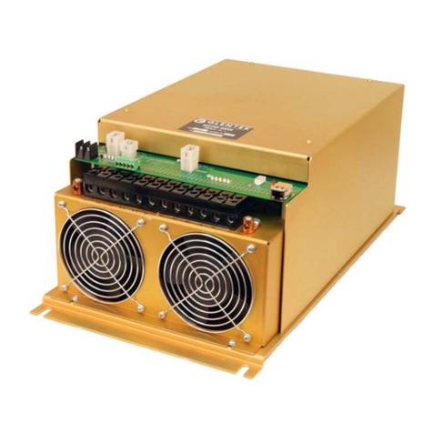
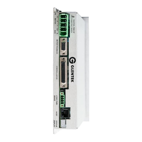
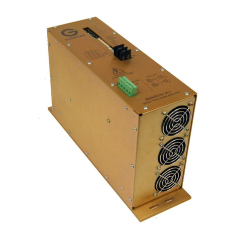
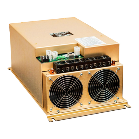
FADAL VECTOR DRIVE
INSTALLATION DRAWING
6889-1
6889-1RB
SMB9675
SMB9675-1A-1 B
M.TAGUPA 10MAR10
J.A.M. 10MAR10
J.A.M. 10MAR10
1:1.25 1 1
±0.01
±0.005
±0.5°
- B INITIAL DRAWING RELEASE 3227 16AUG10 M. TAGUPA J.A.M.
REVISION HISTORY
ZONE REV DESCRIPTION APPDECO CHANGEDDATE
DRAWING TITLE
SCALE:
.XXX
.XX
125
TOLERA NCES ARE A S FOL LOWS:
FINISH:
ANGULAR:
DECIMAL:
APPROVAL
MAXIMUM
=
=CHK BY:
APPBY:
=
DWN BY:
D
SIZE
DATE
OFSHEETFILE NAME:
CONFIGURATIONCODE:
DRAWING NUMBERMODEL REV
THE INFORMATION CONTAINED WITHIN THISDOCUMENTWAS
ORIGINATED BY ANDIS THE EXCLUSIVE PROPERTYOF GLENTEK
INC. THIS PROPRIETA RY INFORMATION SHALL NOT BE RE PRODUCED,
TRAN SFE RRE D TO O THE R D OCUME NTS, DIS CLO SE D TO O THERS,
U SE D FO R MA NU FA CTUR ING O R A NY O THER P URPOSE WITHOUT
PRIO R WRITTEN PERMISSION FROM GLEN TEK, INC.
UNLESS OTHERWISE SPECIFIED
DIMEN SION S AR E IN INCHES
<
P2 Encoder Output Connector
2N/C
TX232
RX232
COM232
6
N/C
N/C
8
7
N/C
4
5
3
SIGNAL NAME
N/C
PIN
1
Not Available
Analog Out
P4 Inverter Encoder Connector Pins
P4 InverterEncoderConnector 9-Pin Molex
P5 / P6 Control Connector Pins
Dimension (L x H x W - inches)
P3 Host RJ45
P5 / P6 Control Connectors 6-Pin Molex
Non-Volatile Memory
Storage Temperature
Mounting Hardware
Backup File
Humidity
Amplifier Isolation
Operating Temperature
Current Loop Bandwidth
PWM Switching Frequency
Digitally Tuned
Software Configurable
RS-232 Host Port
at Amplifier turn on
Smart Com Initialization
Auto Phasing
Glentek P/N: EJD21F09; Molex P/N: 02-09-1119
Glentek P/N: EJ761M09; Molex P/N: 03-06-1092
Glentek P/N: EJ018083; Molex P/N: 87522-8012
Glentek P/N: EJD21F06; Molex P/N: 02-06-1103
Glentek P/N: EJ588M06; Molex P/N: 03-09-1064
Logic completely isolated from high voltage output stage
All parameters are stored in non-volatile memory
Mating Connectors
L. 20.75, H. 8.02 W. 11.20
5% to 95% non-condensing
5/16 x .75
-40 °C to +80 °C
6889-5.BK
0 °Cto +60°C
Tunable up to 3 KHz
5 KHz Standard
High speed serial communication interface for set-up
All parameters set digitally. No potentiometers to adjust.
RS-232 high speed serial communication interface for
and tuning. 115.2 Kbaud, 8 bits, no parity, 1 stop bit
Glentek's Windows based MotionMaestro software.
Allparameters are downloaded using the RS232 port /
all gain and PID tuning parameters.
Not Available
Not Available
TM TM
Dedicated Fault Output
(Progammable Level) TTL Compatible
Specifications and Features
Tachometer Feedback
Dedicated Inputs
Auxiliary Analog Input
Pulse & Direction Inputs
Encoder Feedback
LowSpeed Electronic
Amplifier Type
Bus Overvoltage
Bus Undervoltage
Circuit Breaker (LS/ECB)
Analog Command Input
Amplifier Status Indication
Logic Power
Peak Current Output
Continuous Current Output
Fault Protection
AC Input Voltage
Inhibit
Not Available
Not Available
Accepts TTL level encoder signals
Not Available
Latches when programmable current (75 A max.),
Trips nominally at 450 ± 10 VDC
Trips nominally at 150 ± 10 VDC
Sensored Vector Drive
±10V for analog velocity command
See Table
240 VAC 3-phase
Logic power is derived from input BUS Voltage.
125 A @ 25°C Ambient (with forced air cooling)
75 A @ 25°C Ambient (with forced air cooling)
Short circuit protection frommotor phase to phase,
Powers all amplifier logic and encoders (250 mA max.)
(chassis gnd) Amplifier RMS over current. DC bus
broken wire. Invalid Hall/comm track state.
over temperature (switch or thermistor input). Encoder
over/under voltage. Amplifier over temperature. Motor
Commutation fault.
motorphase to DCbus, motor phase to case
and time (10 sec max.) exceed limit.
9EAOUT+
EBOUT-
EBOUT+
EAOUT-
11
12
10
SIGNAL NAME
GND
PIN
8
P3 Host Connector
P1 Load Meter Connector
2RED+
SIGNAL NAME
BLACK -
PIN
12+5V
B +
INDEX +
B -
6
A -
A +
8
7
GND
4
5
3
SIGNAL NAME
SHIELD
PIN
1
P4 Encoder Input Connector
INDEX -9
2N/C
N/C
N/C
COMMON FOR WYE DELTA
6
HI GAIN/(LOW GAIN INPUT)
4
5
3
SIGNAL NAME
WYE/(DELTA INPUT)
PIN
1
P6 Wye/Delta Connector
2 (SPINDLE REVERSE)
(SPINDLE FAULT)
SPINDLE SPEED
CMD COMMON
6
(SPINDLE FORWARD)
4
5
3
SIGNAL NAME
SPINDLE COMMON
PIN
1
P5 Inverter Control Connector
L2 3 PHASE AC INPUT
NOT AVAILABLE
B-OUTPUT
NOT AVAILABLE
B-
REGEN RESISTOR IN
REGEN RESISTOR IN
R2
R1
3 PHASE AC INPUT
N/C
N/C
L3
SIGNAL NAME
3 PHASE AC INPUT
PIN
L1
Motor Power Connector
B+ OUTPUTB+
MOTOR OUTPUT PHASE
MOTOR OUTPUT PHASE
T2
T1
MOTOR OUTPUT PHASET3
S HS/ECB
UNDER VOLTAGEU
CCLAMP
NORMAL OPERATION
ENCODER FAULT
HEATSINK OVERTEMPH
L
OLS/ECB
E
RESET(FLASHING)
BUS OVERVOLTAGE
Status Display
EEPROM FAULT
FAULTDESCRIPTION
b
8
DISPLAY
1