Safety Voltages
DC voltage ±200 V
Channel-to-earth ground isolation
Continuous 250 V DC, Measurement Category I
Withstand 1000 Vrms, verified by a 5 s withstand
Measurement Category
Caution Do not connect the product to signals or use for measurements within Measurement Categories II, III, or IV.
Attention Ne pas connecter le produit à des signaux dans les catégories de mesure II, III ou IV et ne pas l'utiliser pour effectuer des mesures dans ces
catégories.
Warning Do not connect the product to signals or use for measurements within Measurement Categories II, III, or IV, or for measurements on
MAINs circuits or on circuits derived from Overvoltage Category II, III, or IV which may have transient overvoltages above what the product can
withstand. The product must not be connected to circuits that have a maximum voltage above the continuous working voltage, relative to earth or to
other channels, or this could damage and defeat the insulation. The product can only withstand transients up to the transient overvoltage rating without
breakdown or damage to the insulation. An analysis of the working voltages, loop impedances, temporary overvoltages, and transient overvoltages in
the system must be conducted prior to making measurements.
Mise en garde Ne pas connecter le produit à des signaux dans les catégories de mesure II, III ou IV et ne pas l'utiliser pour des mesures dans ces
catégories, ou des mesures sur secteur ou sur des circuits dérivés de surtensions de catégorie II, III ou IV pouvant présenter des surtensions transitoires
supérieures à ce que le produit peut supporter. Le produit ne doit pas être raccordé à des circuits ayant une tension maximale supérieure à la tension de
fonctionnement continu, par rapport à la terre ou à d'autres voies, sous peine d'endommager et de compromettre l'isolation. Le produit peut tomber en
panne et son isolation risque d'être endommagée si les tensions transitoires dépassent la surtension transitoire nominale. Une analyse des tensions de
fonctionnement, des impédances de boucle, des surtensions temporaires et des surtensions transitoires dans le système doit être effectuée avant de
procéder à des mesures.
Measurement Category I is for measurements performed on circuits not directly connected to the electrical distribution system referred to as MAINS voltage.
MAINS is a hazardous live electrical supply system that powers equipment. This category is for measurements of voltages from specially protected secondary
circuits. Such voltage measurements include signal levels, special equipment, limited-energy parts of equipment, circuits powered by regulated low-voltage
sources, and electronics.
Note Measurement Categories CAT I and CAT O are equivalent. These test and measurement circuits are for other circuits not intended for direct
connection to the MAINS building installations of Measurement Categories CAT II, CAT III, or CAT IV.
Current Ratings
DC current range ±1 A; ±3 A, pulse only
Safety Compliance Standards
This product is designed to meet the requirements of the following electrical equipment safety standards for measurement, control, and laboratory use:
• IEC 61010-1, EN 61010-1
• UL 61010-1, CSA C22.2 No. 61010-1
Note For safety certifications, refer to the product label or the Product Certifications and Declarations section.
Safety Guidelines for System Design and Implementation
The PXIe-4137 is capable of generating hazardous voltages and working within hazardous voltage systems. It is the responsibility of the system designer,
integrator, installer, maintenance personnel, and service personnel to ensure the system is safe during use.
• Ensure operators cannot access the PXIe-4137, cables, the device under test (DUT), or any other instruments in the system while hazardous voltages are
present.
• Operator access points can include, but are not limited to, guards, gates, sliding doors, hinge doors, lids, covers, and light curtains.
• If using a test fixture enclosure, ensure that it is properly connected to safety ground.
• Ensure that the PXIe-4137 is properly secured to the chassis using the two front panel mounting screws.
• Double insulate all electrical connections that are accessible by an operator. Double insulation ensures protection if one layer of insulation fails. Refer to
IEC 61010-1 for specific insulation requirements.
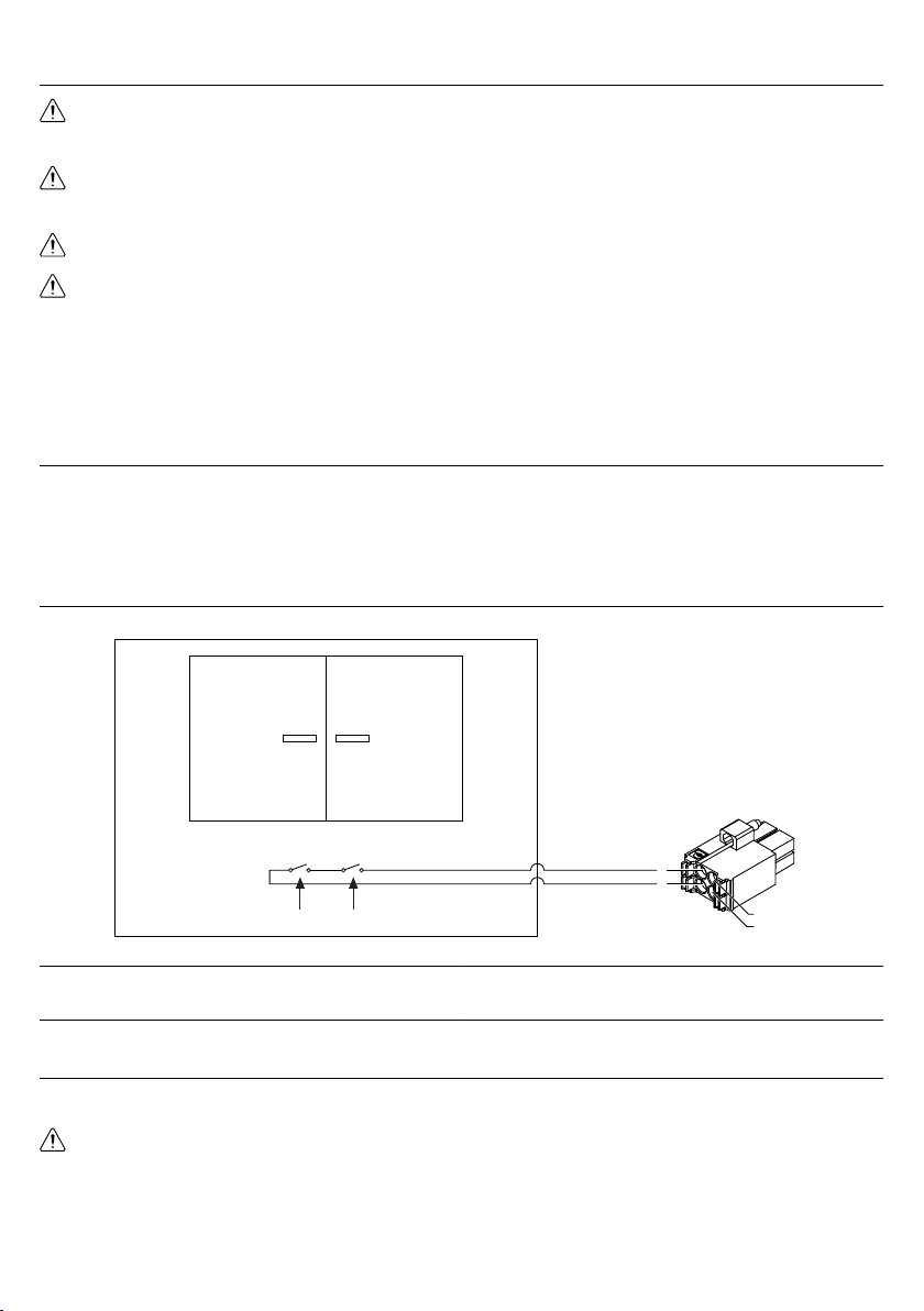
Mechanical Detection Switch Recommendations
• Use high-reliability, fail-safe, normally open mechanical detection switches on all access points to the test fixture enclosure.
• Use two normally open switches wired in series so that a single switch failure does not compromise safety protections.
• Isolate switches so the operator cannot trigger or bypass the switches without the use of a tool.
• Ensure the switches' certifications meet your test application requirements. NI recommends UL-certified safety switches to ensure reliability.
• Install the switches in accordance with the switch manufacturer specifications.
• Test the switches periodically to ensure proper implementation and reliability.
2| ni.com | PXIe-4137 Safety, Environmental, and Regulatory Information