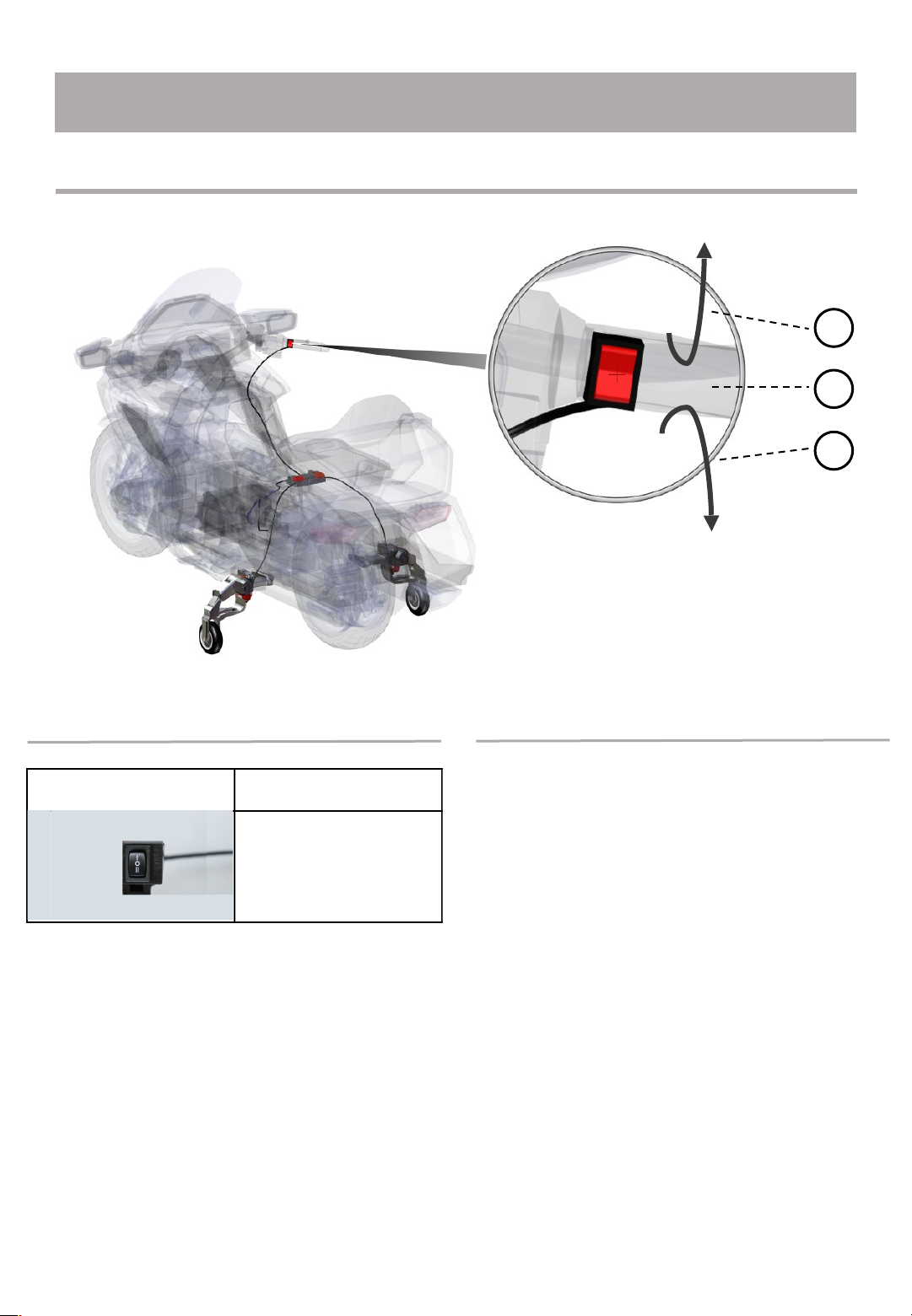
GLK Flex Gear User manual

User Manual
GLK FLEX GEAR 시스템
Version 3.0
No. OM-FC209-101
Model: “FLEX GEAR”
GLX-FC209
글꼴 : Yoon 초록우산어린이

Index
Parts list …………………………….……………….
…………………
FLEX GEAR parts list
Switch ……………………….………………..….…..
…….…….…
Control Box & Cable …………………………….….
…………………..……..……
FLEX GEAR ………………………….….
………………………...………..
FLEX GEAR functions
5
6
2
4
5
5
12
13
14
11
Bracket & FLEX GEAR install
Goldwing 1800 after 2018y ………………….…………….…..
……………..
Goldwing 1800 before 2017y ………………….…………….…..
…………….
Customer Service
Manual Guide …………………………….……………….
………………… 4
Goldwing 1500…………………………………….…………….…..
…………….
Harley Davidson………………………………….…………….…..………….
BMW K1600……………………………………….…………….….………….
Indian……………………………………………….…………….….……….
Kawasaki VN1700 Voyager…………………………….…………….…..……….
FLEX GEAR install ……………………………………….…………….…..
……….
Revision ………………….……………………………….………..…..…….…..
…
Warrenty & Conditions .……….……………………………….……………….
………
Q&A ………………………..………………..……………………..…
Check of Problem …………..………………………..…………......…..
……………..
42
Appendix
42
43
46
47
Start & Stop ..…….……….……………………………….……................
Operation Guide 40
40
39
Cautions
Control Box & Cable connection 35

Customer Service
GLK Co., Ltd.
If you have any questions about GLK FLEX GEAR, please contact us or the place
of purchase.
We will respond to you at the GLK customer center or the place of purchase.
Please contact us through the following contact information:
1. Please read the user manual included with this product.
2. Please access the website address: www.flexgear.co.kr
3. Please contact our office number: 031-999-6799
4. Please contact us by email: flexgear@flexgear.co.kr
5. Please read the product usage precautions and use it correctly.
6. After installing FLEX GEAR for customer information registration,
please send customer information to the head office.
3
•Specifications or appearance may change without notice due to product
improvement.
•This manual describes how to operate the GLK FLEX GEAR system.
•guide:
Includes precautions to avoid possible product malfunction or damage.
•note:
Includes instructions for optimal use and supplementary notes.
User manual guide

FLEX GEAR parts guide
Parts
Please check the components below.
For detailed dimensional data for each part, please refer to the 'Spec Data' page.
Control Box
Cable
Switch Cable
Battery Cable
FLEX GEAR Cable x 2 ea
FLEX GEAR
Left Right
4
Bracket
Sliding Bracket
Middle Bracket Mount Bracket
※Brackets have different shapes and names depending on
the model and year of the motorcycle.

FLEX GEAR Functions
FLEX GEAR Tip
•You can comfortably stand on your motorcycle when stopped.
If you are driving in the city, you will often be waiting for a signal at an intersection. With
the FLEX GEAR, you don't have to support the motorcycle with both legs.
•This is convenient for repeating stops when the vehicle is jammed.
Since motorcycles can't speed on narrow roads, it's even harder to stay centered. With
FLEX GEAR, you can only focus on the direction of the steering wheel when driving
slowly on narrow roads.
•Helps avoid falling when turning or making U-turns in narrow alleys.
If you have two or more people on a motorcycle, it becomes even more difficult to
balance. If you use the FLEX GEAR, you can minimize the shaking caused by the
passenger.
•Convenient for moving your motorcycle in a parking lot or garage.
There may be times when you are stuck in a parking space by an outside vehicle and
cannot ride your motorcycle. In this case, you will have to pull the motorcycle to get it out.
With the FLEX GEAR, you can move heavy bikes comfortably, reducing the risk of tripping
and other accidents.
•Helps prevent slipping at gas stations or underground parking lots with
slippery floors.
When reversing, there are many things you need to pay attention to, such as centering the
motorcycle, checking the surrounding environment, and securing visibility. With the FLEX
GEAR, you can focus more on the external environment to prevent accidents.
•When stopped, passengers in the rear seat can feel comfortable.
Due to the nature of large motorcycles, when the vehicle is congested, stopping
repeatedly causes fatigue to accumulate. Depending on the road conditions, you can use
the FLEX GEAR to drive comfortably.
Cautions
!
Before operating the FLEX GEAR, please read all attached warnings and instructions before
using it to prevent personal injury or property damage.
5
It's really hard for a rider to get up a motorcycle that has fallen over. With the FLEX
GEAR, you don't have to worry about losing your center of gravity and falling.

Image
Name
Switch
Parts name & Functions
Switch
A manual switch is used to prevent
unintentional movement of the FLEX
GEAR while riding a motorcycle.
The FLEX GEAR takes about 2 seconds to
complete.
1. When the green button on the switch is
pressed, the FLEX GEAR goes up.
2. If the button on the switch is not
pressed, the FLEX GEAR will not
move.
3. When the red button on the switch is
pressed, the FLEX GEAR goes down.
Parts name Functions
※Switch may be provided differently for each motorcycle
model.
6
이미지 변경 필요
스위치 사진 변경 필요

Image
Name
Control Box
Control Box & Cable
The LED sensor on the control box
indicates the operating status of the FLEX
GEAR.
If the LED sensor does not light, check the
connection status of each cable.
①Left FLEX GEAR : Lifting
②Left FLEX GEAR : Completed
③Left FLEX GEAR : Landing
④Left FLEX GEAR : Completed
⑤Power
⑥Right FLEX GEAR : Completed
⑦Right FLEX GEAR : Landing
⑧Right FLEX GEAR : Completed
⑨Right FLEX GEAR : Lifting
Name Function
Image
Name
Switch Cable
Power Cable
FLEX GEAR
Cable
7
컨트롤박스 변경 예정

FLEX GEAR
Lifting
Landing
8
Function
①FLEX GEAR Landing / Lifting position control
②Auto fuse / Circuit breakers
The more you push the landing limit sensor into the motorcycle, the more the FLEX GEAR will unfold, and the
more you pull it outward, the less it will unfold.
The more you push the lifting limit sensor into the motorcycle, the more the FLEX GEAR folds, and the more
you pull it outward, the less it folds.
Auto fuse prevents motor overload.
If the auto fuse protrudes about
10mm,After 10 seconds, press to return
to the original position.
Stick
out
Bottom Landing
Sensor
Top Lifting
Sensor
※If the auto fuse protrudes, the FLEX GEAR does
not work.
Normal

③FLEX GEAR install up/down position control
Functions
By locating the cushioning rubber at the inner point
where the main housing and the middle frame are
connected, external shocks from the road are
minimized.
④Shock Absorption - Rubber Suspension
With the bolts in the photo
tightened all the way
<- If you unscrew the bolt
again The FLEX GEAR
position goes down.
If the bolt is re-tightened
-> The FLEX GEAR
position goes up.
After connecting the sliding bracket and the FLEX GEAR, adjust the installation height
through the tightening degree of the bolts. After that, use the mood bolts to fix the
position.
※For details, refer to the ‘Installation’
page
9
⑤Manual operation function
**Use minus(-) screwdriver.**
If the FLEX GEAR does not work,
You can manually manipulate the FLEX GEAR using a minus screwdriver.
**Right FLEX GEAR**
Turn clockwise = Lifting
Turn counterclockwise = Landing

Please check the installation manual for your motorcycle.
Parts of the motorcycle frame may be damaged in order to assemble the bracket (but
only for some models).
If the installation of the bracket is hindered by accessories other than the FLEX GEAR,
please remove the accessory.
Install
Bracket & FLEX GEAR install
Cautions
!
10

Goldwing 1800 after 2018y
11
Sliding bracket
Middle bracket
Mount bracket
ⓐ
ⓑ
ⓒ
ⓓ
ⓕ
ⓔ
Bolt A: M8 35mm / hex socket head bolt +
Bolt B: M8 35mm / hex socket head bolt
Bolt C: M8 25mm / hex socket head bolt
Bolt D: M10 55mm / hex socket head bolt +
Bolt E: M10 10mm / hairless wrench bolt +
Bolt F: M6 10mm / round head bolt
Bracket cover
Spring washer
Flat washer
※Bracket modeling is subject to change due to design modification.
※Bracket bolt dimensions are subject to change due to modeling
modifications.
1
2
4
3
8
7
Remove the motorcycle side cover and footrest cover Remove the muffler cover
Connect the ‘middle bracket’ and
‘mount bracket’ using ‘bolt B’.
Attach the assembled bracket to the front of the blue circle and the back of
the red circle of the motorcycle using ‘bolt A’ and a spring washer.
Reassemble the motorcycle's muffler cover.
Connect ‘Sliding Bracket’ to ‘Intermediate Bracket’
using ‘Bolt C’.
Bracket parts

Sliding bracket
Goldwing 1800 before 2017y
12
Middle bracket Mount Bracket
ⓐ
ⓑ
ⓓ
ⓒ
ⓕ
ⓔ
Remove the seat of the motorcycle. Remove the appropriate cover from the motorcycle.
Remove the motorcycle's
bumper.
Connect the ‘mount bracket’ using
‘bolt A’ and ‘nut’ to the bumper
position.
Connect the ‘middle bracket’ to the
‘mount bracket’ using ‘bolt B’.
Connect the ‘sliding bracket’ to the ‘middle
bracket’ using ‘bolt C’.Position the wrench bolt
hole of the ‘sliding bracket’ toward the front of the
motorcycle.
Bolt A: M8 40mm headless bolt + M8 Nut
Bolt B: M8 30mm / hex socket head bolt
Bolt C: M8 35mm / hex socket head bolt
Bolt D: M10 55mm / hex socket head bolt +
Bolt E: M10 10mm hairless wrench bolt +
Bolt F: M6 10mm round head bolt
Bracket cover
Spring washer
1
2
3
4
6
7
5
Bracket parts
※Bracket modeling is subject to change due to design modification.
※Bracket bolt dimensions are subject to change due to modeling
modifications.

Sliding bracket Middle bracket Mount bracket
Goldwing 1500
Bolt A: M8 40mm set screw +
Bolt B: M8 35mm / hex socket head bolt
Bolt C: M8 25mm / hex socket head bolt
Bolt E: M10 55mm / hex socket head bolt +
Bolt F: M10 10mm hairless wrench bolt +
Bolt G: M6 10mm round head bolt
Bracket cover
Spring washer
13
ⓐ
ⓑ
ⓒ
ⓕ
ⓔⓓ
ⓖ
M8 nut
Bolt D: M8 35mm / hex socket head bolt
Foot stand bracket
Remove the seat, cover, footrest, etc. Connect the blue wire of the switch to ACC of the motorcycle,
The switch is fixed to the handle grip.
(Fix it to the left or right.)
Fix the bracket as shown in the picture.(The bracket in the photo
may differ from the actual bracket)
There is interference in the part marked in red, so I
cut it with a grinder
Bracket parts
Fix the mount bracket and the intermediate bracket using bolt “B”. Then, use
bolt “A” to secure it to the motorcycle.
Fasten the footrest
bracket with bolt
“D”.
Secure the slide bracket using bolt “C”.
※Bracket modeling is subject to change due to design modification.
※Bracket bolt dimensions are subject to change due to modeling
modifications.

Harley Davidson
14
Mount bracket U Bolt
Bolt A: M8 30mm / hex socket head bolt
Bolt C: 3/8 inch / hex socket head bolt +
Bolt D: M8 25mm / hex socket head bolt
Bolt E: M10 55mm / hex socket head bolt +
Bolt F: M10 10mm hairless wrench bolt + Bracket cover
Spring washer
Middle bracket
ⓐ
ⓑ
ⓒ
ⓓ
Nut B: 3/8 inch Nut
Bolt G: M6 10mm round head bolt
Spring washer
Bracket parts
Sliding bracket
ⓕ
ⓔ
ⓖ
1
2
3
4
7
6
Remove the saddle bag, side cover and seat from the motorcycle.
Loosen the frame fixing bolts of the motorcycle.
Connect ‘Middle bracket’ and
‘Mount bracket’ using ‘Bolt A’.
After inserting the ‘Spring washer’ into the blue circle
bolt hole of the ‘Mount bracket’, connect the
assembled bracket to the motorcycle frame using
‘Bolt C’.
※Bracket modeling is subject to change due to design modification.
※Bracket bolt dimensions are subject to change due to modeling
modifications.

ⓐ
ⓑ
BMW K1600
15
Bolt A: M8 55mm / hex socket head bolt +
Bolt C: M8 25mm / hex socket head bolt +
Bolt D: M8 30mm / hex socket head bolt
Spring washer
Bolt B: M8 50mm / hex socket head bolt
Nut : M8 Nut
ⓓ
ⓒ
ⓕ
ⓔ
ⓖ
Bolt E: M10 55mm / hex socket head bolt +
Bolt F: M10 10mm hairless wrench bolt Bolt + Bracket cover
Bolt G: M6 10mm round head bolt
Spring washer
Mount bracketMiddle bracket
Sliding bracket
Bracket parts
2
1
5
4
3
Use the bolt hole on the cover of the motorcycle. Use the two bolt holes (red circles) on the motorcycle frame.
If you want to fix the FLEX GEAR bracket more firmly, make a hole in the blue circle position on the motorcycle frame and
install the bracket with 3 bolts.
Connect the ‘Mount bracket’ to the motorcycle
frame using ‘Bolts A and B’.
※This is optional.
Tighten the bolt using a nut on the back of the upper
hole of ‘Bolt A’. (If the blue circle part is processed
and bolted, this part is also bolted with a nut.)
Connect ‘Sliding bracket’ to ‘Mount bracket’ using
‘Bolt D’.
Connect ‘Middle bracket’ to ‘Mount bracket’ using
‘Bolt C’ and spring washer.
※Bracket modeling is subject to change due to design modification.
※Bracket bolt dimensions are subject to change due to modeling
modifications.

Indian
Bolt A: M8 35mm hex socket head Bolt
Bolt C: M8 25mm hex socket head Bolt
16
ⓐ
ⓓ
ⓒ
ⓔ
Bolt D: M10 55mm / hex socket head bolt +
Bolt E: M10 10mm hairless wrench bolt Bolt + Bracket cover
Bolt F: M6 10mm round head bolt
Spring washer
ⓑ
Bolt B: M8 30mm hex socket head Bolt
ⓕ
Bracket parts
Mount bracketMiddle bracket
Sliding bracket
3
5
1
2
6
Use the bolt hole (red circle) where you removed
the bumper. To further secure the FLEX GEAR
bracket, use a drill and tap to drill additional holes in
the yellow hole locations on the motorcycle frame.
Install the bracket with a total of 3 bolts.
※Required.
Remove the motorcycle's bumper to install the
FLEX GEAR in the motorcycle's bumper position.
Remove the seat of the motorcycle
Connect ‘Middle bracket’ and
‘Mount bracket’ using ‘Bolt B’.
7
Connect the assembled bracket
using ‘Bolt A’ to the location where
the motorcycle bumper was
removed.
Connect ‘Sliding bracket’ to ‘Middle
bracket’ using ‘Bolt C’.
※Bracket modeling is subject to change due to design modification.
※Bracket bolt dimensions are subject to change due to modeling
modifications.

Kawasaki VN1700 Voyager
17
Bolt A: Use of existing motorcycle bolts +
Bolt C: M8 55mm / hex socket head bolt+
Bolt D: M8 25mm / hex socket head bolt
Spring washer
ⓐ
ⓑ
ⓒ
ⓓ
ⓕ
ⓔ
ⓖ
Nut B: M8 55mm / hex socket head bolt +
Spring washer
Spring washer
Bolt E: M10 55mm / hex socket head bolt +
Bolt F: M10 10mm hairless wrench bolt Bolt + Bracket cover
Bolt G: M6 10mm round head bolt
Spring washer
Bracket parts
Mount bracketMiddle bracket
Sliding bracket
1
2
4
3
5
6
Fix the mount bracket using “A” and “B” bolts at the place where the footrest was removed.(It is
recommended to work after removing the muffler cover as there is interference.)
Fasten the foot stand bracket using bolt “C” and install the
slide bracket using bolt “D”.
Connect the blue wire of the switch to ACC, and insert the
switch cable into the control box.
※Bracket modeling is subject to change due to design modification.
※Bracket bolt dimensions are subject to change due to modeling
modifications.

FLEX GEAR install
18
Insert the FLEX GEAR into the slot of the sliding bracket and fasten it.
Push up the fastened FLEX GEAR along the sliding bracket.
1
After raising the FLEX GEAR to the top of the
sliding bracket, insert the ‘Spring washer’ into
the hole of the sliding bracket, and then use
the ‘M10 55mm’ bolt to connect the FLEX
GEAR to the bracket.
After adjusting the height, use the ‘M10
10mm’ bolt to fix the installation position of
the FLEX GEAR.
Assemble the ‘Bracket cover’ using ‘M6
10mm’ bolts.
2
5
3
4
Adjust the height of the FLEX GEAR using
the ‘M10 55mm’ bolt.
Recommendation:
It is recommended to lower the FLEX
GEAR while the driver is riding and set it so
that both wheels touch the ground.

Control box positioning may vary by motorcycle model. You will work by opening the
seat or saddle bag of the motorcycle. Please check the manufacturer's manual for
details on the contents.
but, Even with the same motorcycle model, the manual may differ depending on the
situation of the motorcycle you have. Please check and install the safest and most
appropriate location in the motorcycle interior.
Control Box & Cable connection
Cautions
!
19

Control box install position
1
Position the control box under the seat or inside the saddlebag.
※Check the most appropriate location according to the motorcycle model
you have.
Cable connection to Battery
1
2
Connect the power cable to the control box.※Check the +/-
terminals of the power cable before connecting.
Connect the power cable to the battery inside
the motorcycle.
(The black line is -, the red line is +.)
※Depending on the motorcycle model, the
location of the battery may be different.※
Check the +/- terminals of the battery cable
before connecting.
20
This manual suits for next models
1
Table of contents