manuals.online logo
Brands
  1. Home
  2. •
  3. Brands
  4. •
  5. Global Fire Equipment
  6. •
  7. Security Sensor
  8. •
  9. Global Fire Equipment Vulcan 2 DS User manual

Global Fire Equipment Vulcan 2 DS User manual

TECHNICAL SPECIFICATIONS
Vulcan 2 DS
Detector Sounder/ Beacon
ORDER CODE DESCRIPTION
VULCAN 2 DETECTOR SOUNDER
VULCAN 2 SOUNDER WITH ISOLATOR
VULCAN 2 DETECTOR SOUNDER WITH BEACON
VULCAN 2 DETECTOR SOUNDER WITH BEACON WITH ISOLATOR
VULCAN 2 DETECTOR BEACON
VULCAN 2 DETECTOR BEACON WITH ISOLATOR
LID FOR VULCAN 2
TRANSPARENT LID FOR VULCAN 2
DETECTOR
VULCAN 2 DS
VULCAN 2 DSI
VULCAN 2 DSB
VULCAN 2 DSBI
VULCAN 2 DB
VULCAN 2 DBI
VULCAN 2 L
VULCAN 2 LT
NOTE: Add to sounder/ beacon current when active, conventional detector current in alarm which is internally limited to a maximum of 12 mA.
Loop In/Out
Address|A|B|S
- Vol +
T - Tone
T
M - Mode
M
Loop In/Out
Detector
Sounder
LOOP
OUT
LOOP
RETURN
PANEL
Detector
Base
Volume
Adjustment
red wire
black wire
Normal Sounder Optical Detector
T M
1 2 34
Heat Detector
T M
1 2 34
Mode Selection
T - Tone
M - Mode
T M
ALTERNATING
LOW-FREQUENCY TONE
800-1000 Hz
T M
T M
T M
T M
SWEEPING
TONE
800-1000 Hz
ALTERNATING
HIGH-FREQUENCY TONE
2.7 KHz-3.2 KHz
CONTINUOUS
TONE
800 Hz
CONNECTIONS AND TONE/MODE SETTINGS
When connecting the conventional detector always follow the manufacturer’s instructions to ensure proper operation.
NOTE: If Mode (M) SW 3 & SW 4 are set to OFF, the device will behave like a normal addressable sounder.
In this mode no detectors, conventional or analogue addressable can be connected to this sounder unit.
The shadow sounder mode will still be available by placing switch no. 8 in the OFF position.
SOUNDER
2.5 mA
5 mA
2.5 mA
2.5 mA
SOUNDER/BEACON
3.3 mA
6.4 mA
3.3 mA
3.3 mA
SOUNDER W. ISO.
2.65 mA
5.15 mA
2.65 mA
2.65 mA
SOUNDER/BEACON W. ISO.
3.45 mA
6.55 mA
3.45 mA
3.45 mA
SUPPLY VOLTAGE
LOOP CURRENT - QUIESCENT
LOOP CURRENT - SOUNDER/BEACON ACTIVE
Sweeping Tone 800-1000 Hz
Alternating High Freq. 2.7-3.2 KHz
Continuous Tone 800 Hz
Alternating Low-Freq. 800-1000 Hz
LOOP CURRENT - BEACON
MAXIMUM SOUNDER OUTPUT
CABLE SIZE
RESET/START-UP TIMES
PROTECTION CATEGORY
COLOUR / CASE MATERIAL
OPER. TEMPERATURE / MAX. HUMIDITY
DIMENSIONS / WEIGHT
Loop Powered - 20V to 30V DC
430 uA & 550 uA with isolator - add conventional detector quiescent current
Beacon 2.5 mA Beacon with isolator 2.7 mA
97 dB (@ 1 meter - 30 V DC)
0.5-2.5 mm²
20 seconds max.
Type A - Indoor Use - Rating IP21C
White or Red / ABS
o o
-10 C to 55 C / 95% RH Non-Condensing
100 (D) x 50 (H) mm inc. base / 144 g inc. base
MADE IN PORTUGAL - EU
ma_vulcan2ds_01_010002_en_220103
GLOBAL FIRE EQUIPMENT S.A.
Sítio dos Barrabés, Armazém Nave Y, Caixa Postal 908-Z, 8150-016 São Brás de Alportel - PORTUGAL | Tel: +351 289 896 560
Sales: [email protected] | Technical Support: techs@globalfire-equipment.com | www.globalfire-equipment.com
DETECTOR SOUNDER/ BEACON ADDRESS SETTINGS
MORE INFO >> WWW.GLOBALFIRE-EQUIPMENT.COM
D.I.L. SWITCHES CONFIGURATION
1234 5 6 7 8 1234 5 6 7 8 1234 5 6 7 8 1234 5 6 7 8 1234 5 6 7 8 1234 5 6 7 8 1234 5 6 7 8 1234 5 6 7 8
01 02 03 04 05 06 07 08
1234 5 6 7 8 1234 5 6 7 8 1234 5 6 7 8 1234 5 6 7 8 1234 5 6 7 8 1234 5 6 7 8 1234 5 6 7 8 1234 5 6 7 8
09 10 11 12 13 14 15 16
1234 5 6 7 8 1234 5 6 7 8 1234 5 6 7 8 1234 5 6 7 8 1234 5 6 7 8 1234 5 6 7 8 1234 5 6 7 8 1234 5 6 7 8
17 18 19 20 21 22 23 24
1234 5 6 7 8 1234 5 6 7 8 1234 5 6 7 8 1234 5 6 7 8 1234 5 6 7 8 1234 5 6 7 8 1234 5 6 7 8 1234 5 6 7 8
25 26 27 28 29 30 31 32
1234 5 6 7 8 1234 5 6 7 8 1234 5 6 7 8 1234 5 6 7 8 1234 5 6 7 8 1234 5 6 7 8 1234 5 6 7 8
57 58 59 60 61 62 63
1234 5 6 7 8 1234 5 6 7 8 1234 5 6 7 8 1234 5 6 7 8 1234 5 6 7 8 1234 5 6 7 8 1234 5 6 7 8 1234 5 6 7 8
33 34 35 36 37 38 39 40
1234 5 6 7 8 1234 5 6 7 8 1234 5 6 7 8 1234 5 6 7 8 1234 5 6 7 8 1234 5 6 7 8 1234 5 6 7 8 1234 5 6 7 8
41 42 43 44 45 46 47 48
1234 5 6 7 8 1234 5 6 7 8 1234 5 6 7 8 1234 5 6 7 8 1234 5 6 7 8 1234 5 6 7 8 1234 5 6 7 8 1234 5 6 7 8
49 50 51 52 53 54 55 56
1234 5 6 7 8 1234 5 6 7 8 1234 5 6 7 8 1234 5 6 7 8 1234 5 6 7 8 1234 5 6 7 8 1234 5 6 7 8 1234 5 6 7 8
94 95 96 97 98 99 100 101
Sounder 1 Sounder 2 Sounder 3 Sounder 4 Sounder 5 Sounder 6 Sounder 7 Sounder 8
1234 5 6 7 8 1234 5 6 7 8 1234 5 6 7 8 1234 5 6 7 8 1234 5 6 7 8 1234 5 6 7 8 1234 5 6 7 8 1234 5 6 7 8
102 103 104 105 106 107 108 109
Sounder 9 Sounder 10 Sounder 11 Sounder 12 Sounder 13 Sounder 14 Sounder 15 Sounder 16
1234 5 6 7 8 1234 5 6 7 8 1234 5 6 7 8 1234 5 6 7 8 1234 5 6 7 8 1234 5 6 7 8 1234 5 6 7 8 1234 5 6 7 8
110 111 112 113 114 115 116 117
Sounder 17 Sounder 18 Sounder 19 Sounder 20 Sounder 21 Sounder 22 Sounder 23 Sounder 24
1234 5 6 7 8 1234 5 6 7 8 1234 5 6 7 8 1234 5 6 7 8 1234 5 6 7 8 1234 5 6 7 8 1234 5 6 7 8 1234 5 6 7 8
118 119 120 121 122 123 124 125
Sounder 25 Sounder 26 Sounder 27 Sounder 28 Sounder 29 Sounder 30 Sounder 31 Sounder 32
Switches 1-5
Used to configure the
Sounder/Beacon address
Switch 6
Only used for Detector Sounders Address
Switch 7
OFF Beacon stops with ALARM SILENCE
ON Beacon stops with RESET
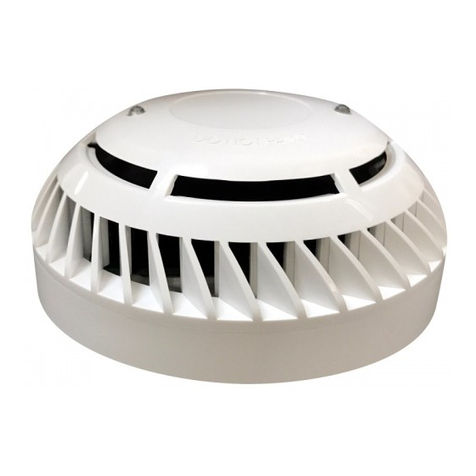
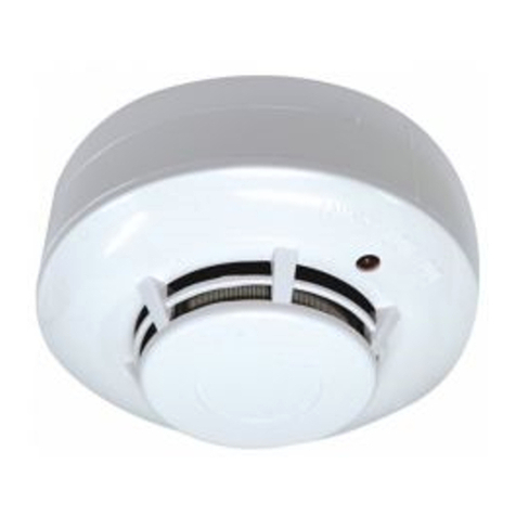
Detector Sounder/ Beacon - The Vulcan 2 Detector Sounder/ Beacon is a Base Sounder and/or Beacon which is also used to interface one
conventional detector to the Analogue Addressable Loop. The number of Detector Sounders/ Beacons connected to each Loop is dependent on
Loop loading and in any case the total number/ loop should not exceed 64. If only detector sounders are used then this number may be
increased to 96 sounders per loop. This includes normal addressable sounder beacons placed between address 94 and 125. These are fully
programmable in sounder groups.
Detector Sounders are always placed between address 1 and 63 and cannot be included in sounder groups. Device will report to the panel as
either a SMOKE or HEAT detector depending on MODE jumper position.
CAUTION: SHADOW Sounder/ Beacon - The Vulcan 2 Addressable Detector Sounder/ Beacon should NOT be configured as a Shadow
Sounder/ Beacon using the 8 – way dip switch provided. Switch 8 should always be in the ON position.
SOUNDER/ BEACON ADDRESS SETTINGS
Address Switches
Binary Weights
1 ON = 1
2 ON = 2
3 ON = 4
1 2 345678
ON (1)
OFF (0)
ON
OFF
Sounder Type
Switch No. 8
OFF = Shadow
ON = Normal
4 ON = 8
5 ON = 16
6 ON = 32
INSTALLATION
This manual suits for next models

7

Other Global Fire Equipment Security Sensor manuals

Global Fire Equipment ZEOS-AD User manual

Global Fire Equipment

Global Fire Equipment ZEOS-AD User manual

Global Fire Equipment ZEOS-AD User manual

Global Fire Equipment

Global Fire Equipment ZEOS-AD User manual

Global Fire Equipment ZEOS-AD User manual

Global Fire Equipment

Global Fire Equipment ZEOS-AD User manual

Global Fire Equipment GFE-SWR Series User manual

Global Fire Equipment

Global Fire Equipment GFE-SWR Series User manual

Global Fire Equipment GFE-S Series Quick start guide

Global Fire Equipment

Global Fire Equipment GFE-S Series Quick start guide

Global Fire Equipment GFE-S Quick start guide

Global Fire Equipment

Global Fire Equipment GFE-S Quick start guide

Global Fire Equipment GFE-H User manual

Global Fire Equipment

Global Fire Equipment GFE-H User manual

Popular Security Sensor manuals by other brands

hyfire HFW-TA-05 quick start guide

hyfire

hyfire HFW-TA-05 quick start guide

Siemens DB720 Installation

Siemens

Siemens DB720 Installation

SWARCO CAIMAN-PRO Series user manual

SWARCO

SWARCO CAIMAN-PRO Series user manual

Technoalarm evolution EV SMK BWL Installation

Technoalarm

Technoalarm evolution EV SMK BWL Installation

KAM OID user manual

KAM

KAM OID user manual

Rosslare SA-01P installation instructions

Rosslare

Rosslare SA-01P installation instructions

InoTec BNP 9100 P Ino-Traq Series Operating	 instruction

InoTec

InoTec BNP 9100 P Ino-Traq Series Operating instruction

Thermo Scientific VC-D60 operating manual

Thermo Scientific

Thermo Scientific VC-D60 operating manual

Amprobe TX900 user manual

Amprobe

Amprobe TX900 user manual

Nabco Acusensor 3 Quick setup

Nabco

Nabco Acusensor 3 Quick setup

Leuze electronic CU411-RS4 Supplement to original operating instructions

Leuze electronic

Leuze electronic CU411-RS4 Supplement to original operating instructions

Kaya Safety P-451 PO user guide

Kaya Safety

Kaya Safety P-451 PO user guide

THORLABS PDA015AM quick start guide

THORLABS

THORLABS PDA015AM quick start guide

MGC MIX-4020 Installation and maintenance instructions

MGC

MGC MIX-4020 Installation and maintenance instructions

resideo TWLD3005-001 manual

resideo

resideo TWLD3005-001 manual

Satel MAGENTA quick start guide

Satel

Satel MAGENTA quick start guide

Brandson Equipment 304973 user manual

Brandson Equipment

Brandson Equipment 304973 user manual

LST 5351E Specification sheet

LST

LST 5351E Specification sheet

manuals.online logo
manuals.online logoBrands
  • About & Mission
  • Contact us
  • Privacy Policy
  • Terms and Conditions

Copyright 2025 Manuals.Online. All Rights Reserved.