Global Industrial 989021 User manual

OPERATOR’S MANUAL
Global Industrial
globalindustrial.com
Manual Part No. 989021M
11/06/2019
POWERED STRADDLE LIFT TRUCK
MODEL 989021


3
FOREWORD
As a lift truck operator, you are respon-
sible for a machine that is useful, pow-
erful, and can be hazardous if not
operated as described. Your Global
Industrial truck may weigh more than
some cars, depending on the model.
Observing and practicing the safety
warnings in this manual cannot be over-
emphasized. Just knowing the warn-
ings, however, is no substitute for
common sense. Focusing on the task
at hand, in almost all cases, prevent
accidents. Think of the truck as your
own. In this way you will learn its capa-
bilities and limitations.
This manual is intended to remain with
the truck at all times as a handy refer-
ence guide to operation. Detailed main-
tenance procedures are found in the
parts and service manual for the spe-
cific truck model, and are to be per-
formed only by a qualified technician.
For further information on obtaining a
c o m p l e t e p a r t s a n d s e r v i c e m a n u a l , s e e
page 26 of this manual.
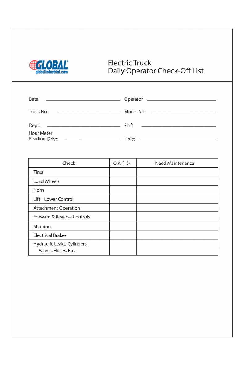
The operator who knows his truck will
learn to spot problems as they develop.
This is accomplished by performing the
Daily Checks and reporting any prob-
lems to the designated authority.
TABLE OF CONTENTS
SAFETY SYMBOLS ..............................................................................................4
GENERAL DESCRIPTION ....................................................................................4
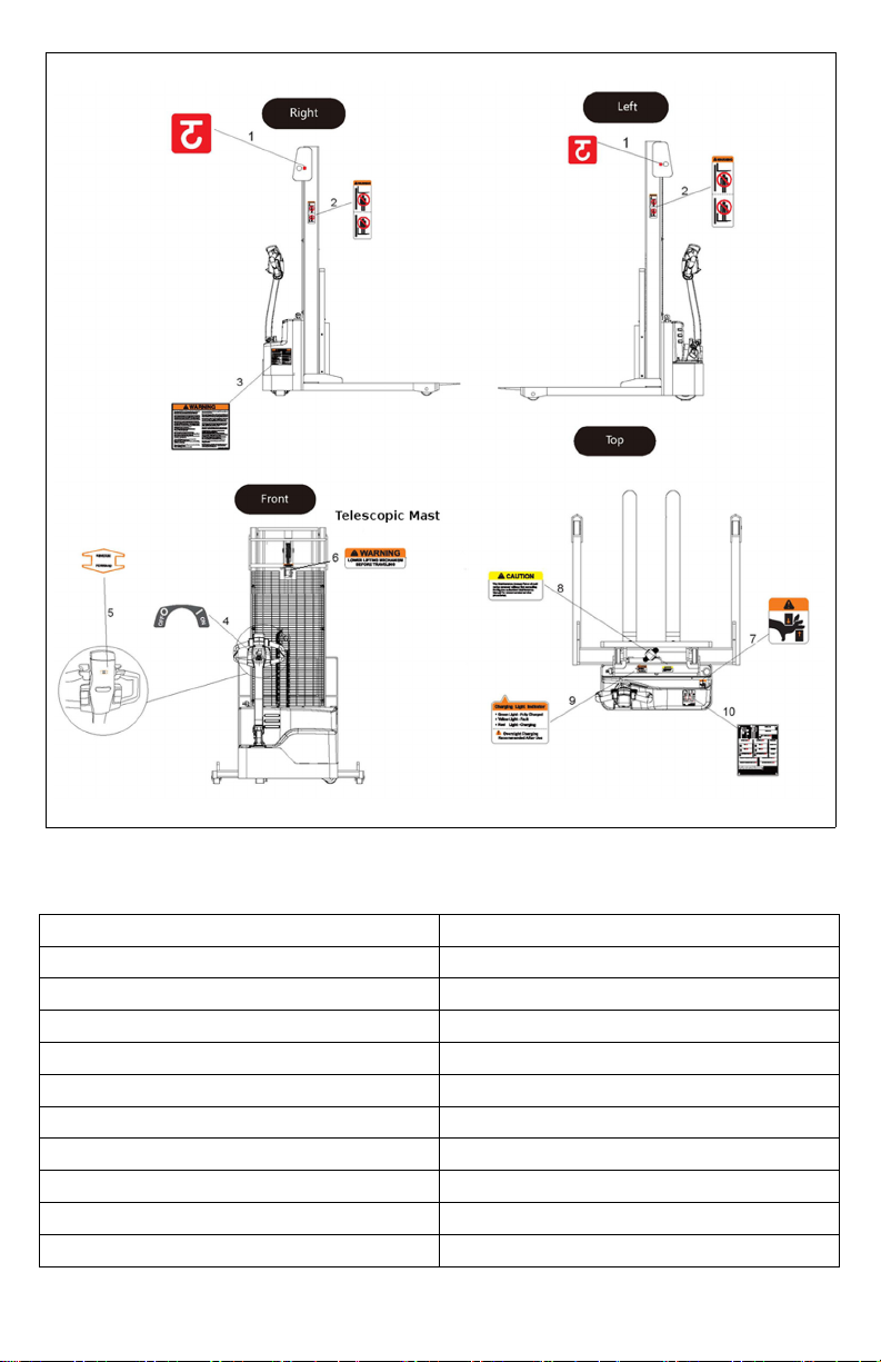
NAME PLATE AND WARNING DECAL ...............................................................4
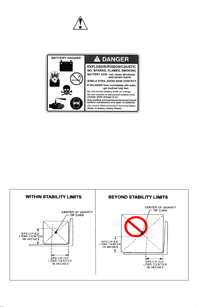
LOAD CAPACITY..................................................................................................6
BEFORE OPERATION ..........................................................................................7
INSTRUMENTS AND CONTROLS .....................................................................10
OPERATION ........................................................................................................11
Forward and Reverse Travel and Speed Control ...............................11
Steering ..................................................................................................11
Stopping.................................................................................................12
Parking ...................................................................................................12
Battery Charging ...................................................................................13
Load Handling .......................................................................................13
Moving a Disabled Truck ......................................................................14
NOTICE - OBTAINING A PARTS AND SERVICE MANUAL..............................26

4
SAFETY SYMBOLS
WARNING and CAUTION are both signal words intended to alert the viewer to
the existence and relative degree of a hazard. They are both preceded by a safety
alert symbol consisting of an exclamation mark enclosed by a triangle.
A Warning indicates a hazard which could result in injury or death if proper pre-
cautions are not taken.
A Caution indicates a reminder of routine safety practices.
A prohibition slash (circle with diagonal slash through it) indicates a procedure or
action that should not be performed under any circumstances, as both personal
injury and/or damage to equipment will result.
GENERAL DESCRIPTION
The Global Industrial Straddle trucks
utilize the straddle leg configuration,
which normally straddles the load.
Control for steering, braking, forward
and reverse travel, horn and speed con-
trol are all located on the control handle.
All trucks feature an automatic high
speed cut-off circuit which locks out
high speed when the forks are elevated.
NAME PLATE AND WARNING DECAL
Warning decal locations are near the
steering arm within sight of the operator.
The name plate is mounted on the
trucks rear cover. See illustration on
next pages
If the name plate or warning decal are
lost or damaged they should be
replaced immediately. Have your
supervisor or the designated authority
contact Global Industrial Authorized
Dealer for replacement.
The name plate shows the model num-
ber, serial number, and truck type. Bat-
tery type, with voltage and minimum
weight, is shown along with information
on the load capacity and load center.
The warning decal contains warnings
which also appear, with illustrations, in
the Operation section of this manual.

5
989021 Name Plate and Warning Decal Locations - Typical
ITEM DESCRIPTION
1 Hook label (indicating lift spot)
2 Mast warning label
3 Warning label
4 Key switch label
5 Forward and Reverse label
6 Warning label
7 Pinch point label
8 Caution label
9 Charger status indicator label
10 Data plate
R8566

6
This truck is equipped with a battery. Read and heed the following warning plus
any other warnings located near or on the battery. An example is shown here:
LOAD CAPACITY
The further the load center is from the
backrest, the lower the load capacity.
The load center must also be no higher
than that specified above the lifting sur-
face (Top side of forks). For example, a
load capacity of 2200 pounds with a
load center of 24 inches means that the
truck can be used to lift 2200 pounds
only when the load’s center of gravity is
no more than 24 inches from the face of
the forks or 24 inches above the top side
of the forks. Note that a truck undergo-
ing speed changes is less stable than a
standing truck. If you are not sure that
the truck can lift a certain load, consult
your supervisor or the designated
authority.
Load Center
WARNING:
R6115
R3814

7
BEFORE OPERATION
The table on page 9 covers important
inspection points on trucks which
should be checked prior to operation.
Depending on use, some trucks may
require additional checks.
The illustration on the next page shows
a sample format for an Operator Check-
list, which can be modified as necessary
to fit your operation.
Periodic maintenance of this
truck by a qualified service
technician is required.
A qualified service technician
should check the truck monthly
for proper lubrication, proper fluid
levels, brake maintenance,
motor maintenance and other
areas specified in the parts and
service manual maintenance
section.
If the truck is found to be unsafe
and in need of repair, or contrib-
utes to an unsafe condition,
report it immediately to the des-
ignated authority. Do not operate
it until it has been restored to a
safe operating condition. Do not
make any unauthorized repairs
or adjustments. All service must
be performed by a qualified ser-
vice technician.
WARNING:
WARNING:
WARNING:

8
R6235GL

9
Sample of Operator Check List
Operator Checks
ITEM PROCEDURE
Transmission and hydraulic
systems
Check for signs of fluid leakage.
Forks Check for cracks and damage and that they
are properly secured.
Chains, cables and hoses Check that they are in place, properly secured
and not damaged.
Guards and load backrest Check that safety guards are in place, prop-
erly secured and not damaged.
Safety signs Check that warning labels, nameplate, etc.,
are in good condition and legible.
Horn Check that horn sounds when operated.
Steering Check for binding or looseness in steering
arm when steering.
Travel controls Check that speed controls on control handle
operate in all speed ranges in forward and
reverse and that belly button switch functions.
Wheels Check drive wheel for cracks or damage.
Move truck to check load wheels and casters
for freedom of rotation.
Hydraulic controls Check operation of lift and lower to their maxi-
mum positions.
Brakes Check that brakes actuate when steering arm
is raised to upright position, and when lowered
to horizontal position.
Deadman/Parking brake Check that steering arm raises to upright posi-
tion when released and brake applies.
Battery disconnect Check that battery can be disconnected and
reconnected. Check for connector damage.
Check that the emergency power disconnect
is functioning properly.
High speed limit switch Allow for enough space to operate truck in
high speed. Elevate forks approximately two
feet, then test drive truck to check if high
speed is cut out.

10
INSTRUMENTS AND CONTROLS
The steering arm and control handle
provide controls for steering, forward
and reverse speed control, braking,
horn, and raising and lowering the forks.
Control handles on all models have a
“belly button” reversing switch which
reverses the direction of the truck upon
contact with the operator.
Detailed operating instructions are in
the Operation section of this manual.
Pushing the red emergency stop switch
removes all power from truck circuits in
the event of an emergency.
Controls
R8568
R8567

11
OPERATION
Forward and Reverse Travel and
Speed Control
Control Handle
All directional and speed controls are
located on the control handle.
Forward and reverse are controlled by
rotating the speed control lever as
shown. The lever is spring loaded to
return to neutral when released. Further
rotation in either direction will progress
the truck from slow to maximum travel
speed.
To change directions or to stop the truck,
rotate the speed control lever in the
opposite direction. The truck will come
to a stop and then, unless the controls
are returned to the center neutral posi-
tion, accelerate in the opposite direc-
tion.
Steering
Moving the control handle (which con-
nects to the steering arm) right or left will
turn the truck right or left. When maneu-
vering around corners, make square
turns and be sure there is
adequate clearance.
R8567

12
Stopping
Stop the truck as gradually as possible.
Unnecessary rapid stopping could be
hazardous. Load could become unsta-
ble.
You can use plugging to stop the truck,
this electrical braking function consists
of rotating the speed control lever in the
opposite direction of travel and then
releasing it when the truck stops. Plug-
ging is a convenient way to stop the
truck during normal operation. If the
control is not released, the truck will
accelerate in the opposite direction.
You can also stop the tucks movement
(forward or reverse) by raising the con-
trol handle to the up position or push the
control handle all the way down. In
either positions, the travel controls will
deactivate and the brake will apply. To
release the brake, just move the control
handle to the operating position.
NOTE: The steering arm return
spring automatically raises
the steering arm to the
upright position when the
steering arm is released.
CAUTION: If the control handle does
not raise immediately to
the vertical position when
released, the truck should
be placed “OUT OF SER-
VICE” until it can be
inspected by a qualified
repair technician.
Steering Arm Braking Positions
Parking
When parking the truck, do not obstruct
traffic lanes or aisles.
1. Park the truck in its designated
parking area.
2. Raise the steering arm until vertical
to apply the parking brake.
3. Fully lower forks and make sure the
lift carriage is all the way down.
4. Turn keyswitch to off position.
Remove key for added security.
5. Pushing the red emergency stop
switch removes all power from truck
circuits in the event of an emergency.
Do not use as an On/Off switch since
it will wear the contactor prematurely.
R8569

13
Battery Charging
Refer to page 24 for battery safety and
maintenance.
NOTE: Battery charging instructions
are contained in the service
manual.
Load Handling
Handle only loads arranged for
stability and always use caution.
Raise and lower the load
smoothly to prevent the load from
falling.
Always be sure the load and load
center are within the capacity of
the truck. If in doubt check the
nameplate.
1. Approach the load slowly.
2. Stop the truck when the forks are just
in front of the load.
3. Adjust the forks to the maximum
practical width to support the load to
be lifted.If the truck has rigid forks,
position the truck so the forks will
give maximum support to the load.
4. Raise or lower the forks until they are
properly aligned with the pallet open-
ings.
5. Move the truck slowly into position so
that the forks are centered about the
load.
6. Make sure the load is against the
backrest and then raise the forks until
the pallet clears the rack.
7. Move the truck away from the rack
until the load clears the rack and then
lower the forks.
8. Always operate the truck with the
forks in the DOWN position and
slightly raised when operating on a
grade.
9. Lead the truck by the control handle
with the load trailing except when in
confined areas. Ramps should
always be traveled with operator
uphill of truck.
10. Always look in the direction of travel.
Move slowly and check clearances
when approaching obstructions.
11. Do not make sudden starts and
stops. Operate truck smoothly and
gradually.
12. Travel slowly and squarely around
corners. Remember that the trailing
load wheels do not follow the turn
path of the drive wheel; instead, they
tend to cut the corner.
13. Line up the truck with the unloading
area.
14. Stop the truck and raise or lower the
forks until the pallet is in position with
the unloading area.
15. Check the load alignment with sur-
rounding objects.
16. Be careful not to damage or move
adjacent loads and objects.
17. Slowly move into position.
18. Lower the forks until the load is
securely settled on its own. Be sure
there is no downward force on the
forks on the rack or floor.
WARNING:
WARNING:

14
19. Carefully move the truck away from
the load watching to make sure the
load doesn’t move or shift. If the load
does move, return the truck to the
load and reset.
NOTE: Make sure when working in a
rack area, that you do not
disturb another load while
placing yours in the rack.
This may cause a danger-
ous situation for other opera-
tors or pedestrians working in
this area later.
20. If forks are elevated, lower to travel
position.
Moving a Disabled Truck
Do not attempt to move a disabled truck;
notify your supervisor or proper author-
ity.

15
The following operating instructions appear on the truck warning decal, which is
located near the steering arm.
Do not operate this truck
unless you have been
trained and authorized to do
so, and have read and
understand all warnings
and instructions contained in
R8588
R8570
Do not operate this truck until you have
checked its condition. Give special atten-
tion to wheels, horn, lights, battery, con-
troller, lift systems (including forks or
attachments, chains, cables and limit
switches), brakes, steering mechanism,
guards and safety devices. If you
have any questions, notify your
supervisor or proper authority.

16
Operate truck only from walking
position.
R8571
Never place any part of the body
into the mast structure.
R8572

17
R8573
Do not carry passengers.
Keep feet clear of truck
and always wear foot pro-
tection
R8577

18
R8574
Observe applicable traffic regulations. Yield right-of-way to pedestrians.
Slow down and sound horn at cross aisles and wherever vision is
obstructed.
R8576
Start, stop, travel, steer and brake
smoothly. Slow down for turns and on
uneven or slippery surfaces that could
cause truck to slide or o v e r t u r n . U s e s p e -
cial care when traveling without load as
the risk of overturn may be greater.

19
Travel with lifting mechanism as low as
possible. Always look in direction of travel.
Keep a clear view, and when load inter-
feres with visibility, travel with load or lifting
mechanism trailing.
R8578
R8579
Use special care when operating on
ramps; travel slowly and do not angle or
turn. Always travel with lifting mechanism
downhill and driver uphill.

20
Do not overload truck. Check
capacity plate for load weight and
load center information.
R8580
When using forks, space forks
as far apart as load will permit.
Before lifting, be sure load is
centered, forks are com-
pletely under load, and load is
as far back as possible against
load backrest.
R8581
Table of contents
Other Global Industrial Forklift manuals