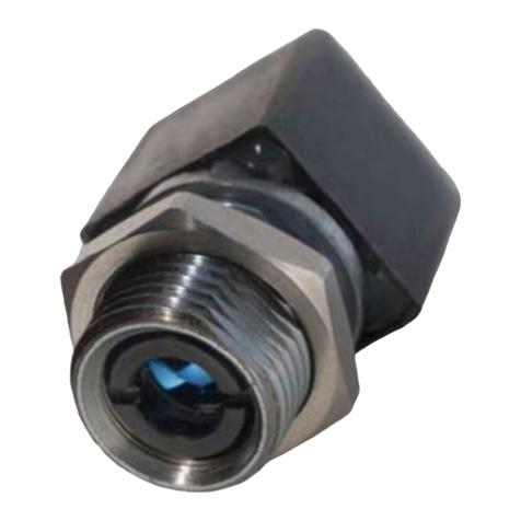
Global Laser Cameo Series User manual

Thank you for purchasing a laser module from the Cameo range. This emits a red/IR spot or projection.
Two models are available, either a CW version (1250) or the Gated version (1260). The Gated version
incorporates a TTL modulatable input capable of 100Khz.
The Cameo range is a miniature laser module that has a threaded barrel for easy bulkhead mounting
which also ensures good thermal contact between module and heat sink. This new concept in laser
module design allows a laser diode, an adjustable collimating lens and a drive circuit to be incorporated
within a body which is just 23mm long and all without compromising the performance. The Cameo
oers high output power stability with transient and polarity protection, as well as electrical isolation
between diode and case. It has a latching connector that improves reliability.
If you have any queries or require help when using the Cameo range please call us on +44(0)1495
212213 or contact your local representative.
Cameo Userguide
Product Overview

B: 1260 Gated Version
Introduction
A common requirement for applications which use photo detectors, cameras and other non-visual
sensing is the ability to rapidly switch the laser output ON and OFF. Simply applying and removing the
supply voltage is rarely satisfactory and in certain cases can result in the destruction of the module.
This is because laser diodes are very sensitive to spikes and surges, which are often the result of
uncontrolled supply switching. To overcome this limitation, the 1260 Gated Cameo has two additional
inputs that are provided to control the output of the laser module in a reliable and predictable way.
Control Input (Pin 3 - Yellow Lead)
A logic LOW level turns the output completely OFF (≤5%). However, applying a logic HIGH turns the
laser ON after a control input delay. This sets the maximum rate at which the module can switch fully
ON and OFF. Bandwidth is ≥ 100Khz.
Enable Input (Pin 4 - Blue Lead)
Some applications require a simple, slow speed ON/OFF Switching (such as an enable switch). The 1260
gated Cameo eliminates the requirement to provide an external switching device by providing a logic
compatible enable input, capable of operating from low power logic and micro-processors. In this OFF
condition, the module draws very little or no current and no light is emitted. The logic input is Non-
inverted.
Pin Connections and Functions
Connect the supplied 4 way JST connector to back of laser.
CW Mode:
To operate laser in CW mode the red, black, yellow and blue leads should be connected to the
following:
A. CW Mode
To operate the laser in CW mode connect the 2 way JST (see diagram A) to back of laser module.
Product Operation
Pin Lead 1250 CW Cameo
Pin 1 Red Lead 3.3Vdc to +5 Vdc
Pin 2 Black Lead 0 Vdc
Pin Lead 1260 Gated Cameo
Pin 1 Red Lead 3.3Vdc to +5 Vdc
Pin 2 Black Lead 0 Vdc
Pin 3 Yellow Lead +V Supply
Pin 4 Blue Lead +V on, -V o

The Cameo laser module is designed to be mounted via its threaded front barrel (M12X1 Thread) ideally
to a metal mounting bracket or bulkhead. To further assist mounting the module is supplied with a nut
which is tted to the front barrel. A tool to t a 15mm nut is required for adjustment. The direct contact
of the barrel to the mount helps to ensure heat sinking and improve laser diode lifetime. To further
improve reliability the barrel is isolated from the laser diode supply voltage at all times. The case
temperature should be kept within the specied range at all times failure to do this could result in
shortened lifetime or catastrophic failure. As a guide, laser diode lifetime decreases by a factor of two
(approx) for every ten degree increase in operating temperature.
There are two mounting clamps available for the Cameo: swivel clamp and pillow block bearing
mount.
Mounting the Cameo in the Swivel Mounting Clamp (See drawing D)
1. Secure the mounting base to a surface
a. You can use 2 x Ø9 mm slots, 4 x Ø4.5 mm holes, and/or 2 x Ø3.5 mm countersunk holes to
achieve this. If mounting via Ø3.5mm countersunk holes, the swivel bracket must be removed
from the base and then reattached after mounting.
2. Loosen A llen screw A (M3)
3. Slide your laser into the mounting hole and then tighten Allen screw A
4. Loosen Allen screw B (M5)
TTL Mode:
With this version, the yellow lead can be utilised to be driven with a TTL input modulation signal.
Mounting & Heatsinking
Cleaning The Optics
Pin Lead 1260 Gated Cameo
Pin 1 Red Lead 3.3Vdc to +5 Vdc
Pin 2 Black Lead 0 Vdc
Pin 3 Yellow Lead Input TTL Signal
Pin 4 Blue Lead +V on, -V o
If the laser pattern becomes fuzzy or unclear, please check the following:
1. Check the laser is in focus.
2. Remove contaminants with a compressed air duster.
3. Contact Global Laser or your local representative if you still have issues.
Note: Handle optics with with care using powder-free latex or nitrile gloves. These prevent the transfer
of oils and debris from hands to optics. Please place the protective cap over the aperture when the
laser is not in use to reduce optical contamination.

Focus Adjustment
Should you need to adjust the focus please follow one of the below methods:
A. Cameo tted with dot optic (S/C2/HG lens)
1. Insert focus key into laser barrel and align with focus control groves.
2. Turn the focus key until desired focus is achieved.
B. Cameo tted with a P lens
1. Taking care not to touch the lens itself, grip the lens assembly at the front of the laser.
2. Turn until the beam is the desired size.
C. Cameo tted with projection optic
1. Remove any external optics, where tted (see drawing B).
2. Insert focus key into laser barrel and align with focus control groves.
3. Turn the focus key until desired focus is achieved.
4. Replace the external optics if tted and rotate to achieve the desired projection.
5. Adjust tilt angle and then tighten Allen screw B
6. Loosen 2 x M4 screws attaching swivel bracket to base
7. Adjust swivel angle and then tighten 2 x M4 screws remains with the user.
Mounting the Acculase in the Pillow Block Bearing Mount (See Drawing E)
1. Secure the mount to your workbench or surface using the 20 x 11 mm oval slots in the base
2. Unscrew the M6 or M8 socket head screws to remove the clamp from the base
3. Separate the black mounting cylinder from the spherical rolling element
4. Insert your laser into the mounting cylinder
5. Replace both halves of the spherical rolling element around the cylinder and hold in place
6. Position the spherical rolling element and mounting cylinder in the curved section of the clamp
and hold in place
7. Replace the other half of the clamp and hold in place
8. Screw the M6 or M8 socket head screws through the clamp and into the base
9. Manually adjust the direction of your laser

These modules are intended for incorporation into customer equipment. They are classied in
accordance with IEC60825-1 2014, which should be consulted prior to designing or using any laser
product.Thefollowinglabelsaresuppliedforattachmenttothecustomer’sequipment,butresponsibility
for compliance with the standard remains with the user.
Safety & Classication
Class 3R 780nm Laser Label
www.globallasertech.com
IEC 60825-1:2014
INVISIBLE LASER RADIATION
AVOID DIRECT EYE EXPOSURE
CLASS 3R LASER PRODUCT
Produc t Descr iption & Name
Produc t Code
Serial Number
Product Description & Name
Product Code
Serial Number
785nm CW <2.95mW
Class 2 Laser Label
www.globallasertech.com
IEC 60825-1:2014
LASER RADIATION
DO NOT STARE INTO BEAM
CLASS 2 LASER PRODUCT
<1mW CW 400-695nm
Produc t Descr iption & Name
Produc t Code
Serial Number
Product Description & Name
Product Code
Serial Number
Class 3R Visible Laser Label
www.globallasertech.com
IEC 60825-1:2014
LASER RADIATION
AVOID DIRECT EYE EXPOSURE
CLASS 3R LASER PRODUCT
<5mW CW 400-695nm
Produc t Descr iption & Name
Produc t Code
Serial Number
Product Description & Name
Product Code
Serial Number
Class 1 Laser Label
www.globallasertech.com
IEC 60825-1:2014
CLASS 1 LASER PRODUCT
Produc t Descr iption & Name
Produc t Code
Serial Number
Product Description & Name
Product Code
Serial Number
Class 3R 850nm Laser Label
www.globallasertech.com
IEC 60825-1:2014
INVISIBLE LASER RADIATION
AVOID DIRECT EYE EXPOSURE
CLASS 3R LASER PRODUCT
Produc t Descr iption & Name
Produc t Code
Serial Number
Product Description & Name
Product Code
Serial Number
850nm CW <3.95mW
Class 3R 980nm Laser Label
www.globallasertech.com
IEC 60825-1:2014
INVISIBLE LASER RADIATION
AVOID DIRECT EYE EXPOSURE
CLASS 3R LASER PRODUCT
Produc t Descr iption & Name
Produc t Code
Serial Number
Product Description & Name
Product Code
Serial Number
980nm CW <6.5mW
Class 3B IR Laser Label
www.globallasertech.com
IEC 60825-1:2014
INVISIBLE LASER RADIATION
AVOID EXPOSURE TO BEAM
CLASS 3B LASER PRODUCT
<500mW CW 700-980nm
Produc t Descr iption & Name
Produc t Code
Serial Number
Product Description & Name
Product Code
Serial Number
Class 3B Visible Laser Label
www.globallasertech.com
IEC 60825-1:2014
LASER RADIATION
AVOID EXPOSURE TO BEAM
CLASS 3B LASER PRODUCT
<500mW CW 400-695nm
Produc t Descr iption & Name
Produc t Code
Serial Number
Product Description & Name
Product Code
Serial Number
Warranty & Repair
If your product develops a fault within 12 months from the date of purchase Global Laser will repair /
replace the product. If you wish to return a faulty product contact your local representative or Global
Laser to obtain a RMA (Return Material Authorisation code) and return to the address below:
Global Laser Ltd
Unit 9-10
Roseheyworth Business Park
Abertillery
Gwent, NP13 1SP
United Kingdom

Mechanical Dimensions
C) Cameo Laser Module with Projection Lens
B) Cameo Laser Module with P Lens
0.855.90
14.00
14.00
0.92 4.50
1.50
1.6024.00
M12 x 1P
11.00Ø
10.95Ø
Locking Nut
39.00 to 37.40
Adjustable Depending Focal Length
Focusing Key Slots 24.00
M12 x 1P
0.92 4.50
1.50
1.60
Locking Nut 0.855.90
14.00
14.00
0.855.90
14.00
14.00
24.00
M12 x 1P
Ø10.70
Ø10.75
28.60
28.55
Locking Nut
0.92 4.50
1.50
1.60
A) Cameo Laser Module with S/C2/HG Lens
0.855.90
14.00
14.00
0.92 4.50
1.50
1.6024.00
M12 x 1P
11.00Ø
10.95Ø
Locking Nut
39.00 to 37.40
Adjustable Depending Focal Length
Focusing Key Slots 24.00
M12 x 1P
0.92 4.50
1.50
1.60
Locking Nut 0.855.90
14.00
14.00
0.855.90
14.00
14.00
24.00
M12 x 1P
Ø10.70
Ø10.75
28.60
28.55
Locking Nut
0.92 4.50
1.50
1.60
0.855.90
14.00
14.00
0.92 4.50
1.50
1.60
24.00
M12 x 1P
11.00Ø
10.95Ø
Locking Nut
39.00 to 37.40
Adjustable Depending Focal Length
Focusing Key Slots 24.00
M12 x 1P
0.92 4.50
1.50
1.60
Locking Nut 0.855.90
14.00
14.00
0.855.90
14.00
14.00
24.00
M12 x 1P
Ø10.70
Ø10.75
28.60
28.55
Locking Nut
0.92 4.50
1.50
1.60
Note: The Gated Cameo wwill have a 4 way JST connector.

Drawings are not to scale.
E) Pillow Block Bearing Mount( M12)
50.00
20.00
11.00 10.00 34.00
16.00
13.00
20.00
37.00
2 Off Socket Head Screws M6 x 35 Long
102.00
130.00
20.00
11.00 14.00 40.00
50.00
16.00
20.00
2 Off Socket Head Cap Screws M8 x 40LG
2 Off M8 Full Nuts
37.00
102.00
130.00
20.00
11.00 12.50 48.00
72.00
18.00
20.00
2 Off M8 Cap Head Scres x 50 Long
54.00
102.00
130.00
D) Swivel Mounting Clamp
SIDE VIEW
12.70
40.00
45.00
FRONT VIEW
MOUNTING
BASE SIDE
5.00
MOUNTING
BASE
50.00
25.00
20.00
20.00
10.00 10.00
3.508.00
40.00
20.00
14.00
14.00
12.00
4 Holes 4.50 Diameter
2 Slots Ø9.00
2 Holes drill Ø4.50 and counterbore
Hex Hole to suit M4 MS full nuts at rear
2 Holes Ø3.50 and
countersunk to suit
M3 Ct/Sunk screws
40.00
22.00
5.00
M3 x 6
11.0 26.0
M12 x 1P Through Insert
16.00

9090-02-031 Rev 4 19/01/2021
T: +44 (0)1495 212213
F:+44 (0)1495 214004
E: sales@globallasertech.com
www.globallasertech.com
Global Laser Ltd
Units 9-10
Roseheyworth Business Park
Abertillery. Gwent NP13 1SP UK
Notes
Manufacturing
Operations Certied
to ISO9001
This manual suits for next models
2
Table of contents
Other Global Laser Control Unit manuals
Popular Control Unit manuals by other brands

Miele professional
Miele professional A 302 operating instructions

Freescale Semiconductor
Freescale Semiconductor MCF5249 user guide

HydroAir
HydroAir 20-0241 manual

steute
steute RF BF 74 SW868 Mounting and wiring instructions

FIRETRACE
FIRETRACE 800095-A installation manual

ZKTeco
ZKTeco TDM95 quick start guide

AVANCIS
AVANCIS PowerMax Strong Safety, installation, and operation manual

Sentiotec
Sentiotec A2 Instructions for installation and use

NI
NI 9231 Getting started guide

Phoenix Contact
Phoenix Contact FL WLAN 1100 user manual

Texas Instruments
Texas Instruments TPS25948EVM user guide

HORNER
HORNER X OCS Series manual