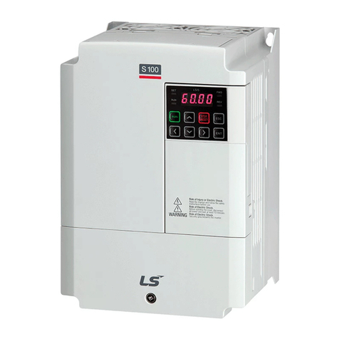
LSIS CENT-S100 User manual

S100 Ethernet Module Manual
i
Before using the product, thank you for using our S100 Ethernet
option module Safety Instruction
To prevent injury and danger in advance for safe and correct use
of the product, be sure to follow the Safety Instructions.
The instructions are divided as ‘WARNING’ and ‘CAUTION’ which
mean as follow.
WARNING
CAUTION
The meaning of each symbol in this manual and on your
equipment is as follows.
This is the safety alert symbol.
This is the dangerous voltage alert symbol..
After reading the manual, keep it in the place that the user always
can contact easily.
Before you proceed, be sure to read and become familiar with the
safety precautions at the beginning of this manual. If you have any
questions, seek expert advice before you proceed. Do not proceed
if you are unsure of the safety precautions or any procedure.
WARNING
Be cautious about dealing with CMOS elements of option
board.
It can cause malfunction by static electricity.
Connection changing like communication wire change must
be done with power off.
It can cause communication faulty or malfunction.
Be sure to connect exactly between Inverter and option
board.
It can cause communication faulty or malfunction.
Check parameter unit when setting parameter.
It can cause communication faulty.
This symbol indicates the possibility of death
or serious injury.
This symbol indicates the possibility of
injury or damage to property.

S100 Ethernet Module Manual
ii
1. Introduction ..............................................................................................1
1.1 What is Ethernet? ......................................................................................1
1.2 Components .............................................................................................1
2. Ethernet Communication Module Features ....................................................2
2.1 Common Features .....................................................................................2
2.2 Layout of Ethernet Communication Module ...................................................2
2.3 Installation ................................................................................................3
2.4 Terminal Block of Ethernet communication Specifications...............................5
2.5 Network Cable Specification .......................................................................6
2.6 Protocol Selection .....................................................................................7
3. LED information.........................................................................................8
3.1 LED display feature....................................................................................8
3.2 The status of Ethernet Line LED (Ethernet/IP and Modbus/TCP are same) ........8
3.3 The status of Modbus/TCP LED & Troubleshooting ........................................9
3.4 The status of Ethernet/IP LED & Troubleshooting......................................... 10
4. Keypad Parameter of Ethernet Communication ............................................ 11
4.1 FBus S/W Ver (CM-06) ............................................................................ 13
4.2 FBus Led (CM-09)................................................................................... 13
4.3 IP Address, Subnet Mask, Gateway (CM-10~15) Setting .............................. 15
4.4 Ethernet Speed (CM-16) .......................................................................... 15
4.5 CIP Input Instance(CM-17) ....................................................................... 16
4.6 CIP Output Instance(CM-18)..................................................................... 17
4.7 Para Status (CM-30~38) .......................................................................... 18
4.8 Para Control (CM-50~58)......................................................................... 18
4.9 Comm Update (CM-94)............................................................................ 18
5. Modbus/TCP........................................................................................... 19
5.1 Modbus/TCP Frame Structure ................................................................... 19
5.2 Function Code Description ....................................................................... 19
5.3 Read Holding Register.............................................................................. 20
5.4 Read Input Register ................................................................................. 21
5.5 Write Single Register ................................................................................ 22
5.6 Write Multiple Register.............................................................................. 23
5.7 Except Frame.......................................................................................... 24
5.8 Exception Frame Structure........................................................................ 24
5.9 Exception Code Type ............................................................................... 24
6. Ethernet/IP ............................................................................................. 25
6.1 Basic protocol configuration ..................................................................... 25
6.2 Implicit Message...................................................................................... 26
6.3 Explicit Message...................................................................................... 34
6.4 Supported Object .................................................................................... 35
7. Lost Command........................................................................................ 46
7.1 Inverter Keypad Parameter ........................................................................ 46
S100 Ethernet Module Manual
1
1. Introduction
1.1
What is Ethernet?
Ethernet communication module board connects the S100
inverter to the Ethernet network. It supports two kinds of protocol,
Modbus/TCP and Ethernet/IP.
Controlling and monitoring of inverter can be done by PLC
sequence program or any Master Module. Since Ethernet which
constitutes Internet has been used and IPv4 has been supported,
wherever Internet can be done, controlling and monitoring is
possible. But, Ethernet network of the factory has to be
connected to Internet through gateway.
Installation time can be reduced and maintenance becomes
easier just simple wiring.
1.2
Components
This product is consisting of these kinds of parts.
- Ethernet Communication Module board (CENT- S100): 1 ea
- Ethernet Module manual: 1 ea
- Brass Bar(M3xL23): 1 ea
- Brass Bar(M3xL17.3): 1 ea
- Fixed Screw(M3xL8): 2 ea

S100 Ethernet Module Manual
2
2. Ethernet Communication Module Features
2.1
Common Features
Transmission Speed
10Mbps, 100Mbps
Transmission Method
Baseband
Max. Extensible Distance
between Nodes
100m (Node-Hub)
Max. Node Number
Hub connection
Auto-Negotiation
Supported
Max. Frame Size
1,500 bytes
Communication Zone Access
Method
CSMA/CD
Frame Error Checking Method
CRC32
Recommended TCP Socket
2 Sockets
2.2
Layout of Ethernet Communication Module
Ethernet Connector
Protocol Select S/W

S100 Ethernet Module Manual
3
(1)
(2)
2.3
Installation
Warning) Connect a communication network after the power supply
is off. If Ethernet communication module is removed or installed, the
power supply should be switched off. Otherwise, the S100 inverter
will be damaged entirely.
Take off Ethernet communication module from the product after the
power supply is totally discharged.
■Unfasten the front cover fixing bolt
to remove the front cover and remove
I/O cover((1), (2)) from
a dedicated S100 inverter
for communication.
■Remove the keypad (3).
■Unfasten a screw from
I/O board and
fasten the prepared
brass bar(4).
(3)
(4)

S100 Ethernet Module Manual
4
■Mount Ethernet communication Module
and fasten the removed screw(6)
and the included screw(7).
■Install the keypad (8) at first and
the communication module
cover(9) in order.
■Install the front cover(10) again
And installation is completed.
(9)
(8)
(10)
(5)
(6)
(7)

S100 Ethernet Module Manual
5
2.4
Terminal Block of Ethernet communication Specifications
※Make sure that cables connected to Pin1 and 2 are twisted together.
※Make sure that cables connected to Pin3 and 6 are twisted together
Pin No.
Signal
Description
Cable color
1
TX+
Transmitting data Plus
White / Yellow
2
TX-
Transmitting data Minus
Yellow
3
RX+
Receiving data Plus
White / Green
4
NONE
Not used
Blue
5
NONE
Not used
White / Blue
6
RX-
Receiving data Minus
Green
7
NONE
Not used
White / Brown
8
NONE
Not used
Brown
8
1

S100 Ethernet Module Manual
6
2.5
Network Cable Specification
Category 5 is used. Transmitting speed of category 5 is 100MHz
and available up to 100Mbps.
Classification
Detail
Used
UTP (U.UTP)
Unshielded
twisted pair
cable
Maximum 200MHz,
Voice + Information (Data)+Low video signal
FTP (S.UTP)
Foil screened
twisted pair
cable
Maximum 100MHz
Electromagnetic interruption (EMI) or
electric stability considered,
Voice+ Information (Data) +
Low Video signal
STP (S.STP)
Shielded
twisted pair
cable
Maximum 500MHz,
Voice +Information(Data)+Video signal,
Replacement for 75Ω coaxial cable

S100 Ethernet Module Manual
7
2.6
Protocol Selection
For using the S100 Ethernet option module, there are 2 kinds of
protocol, Modbus TCP and Ethernet IP. You can select one of the
protocols by selecting the No.1 switch. The switch is placed next
to the Ethernet connector for Ethernet cable. No. 2, 3 and 4 of
switch are not available.
Switch State
Protocol
OFF (Switch at the upper position)
Modbus TCP
ON (Switch at the lower position
Ethernet IP
If the option module is operating, protocol will be not changed
even if switch selection is changed. Protocol is determined by the
state of switch when the option module is turned on or the
inverter is initialized by ‘Yes’ execution of COM-94 Comm Update.
<The bottom side of Ethernet Communication Module >
1 2 3 4
Protocol select S/W (No.1 switch)
Ethernet connector

S100 Ethernet Module Manual
8
3. LED information
3.1
LED display feature
Four LEDs are located on S100 Ethernet Communication Module.
Each LED indicates different functions and displays the status of
Ethernet Protocol for a client.
3.2
The status of Ethernet Line LED
(Ethernet/IP and Modbus/TCP are same)
LED
Color
Status
Function
SPEED
Green
ON
It indicates the communication speed is 100Mbps.
OFF
It indicates the communication speed is 10Mbps.
LINK
Green
ON
It indicates the communication module is ready to
communicate.
OFF
In case of wiring communication cable has a fault,
Link LED is turned Off. Check if wiring is correct.
NS/CPU
MS/ERR
SPEED
LINK

S100 Ethernet Module Manual
9
3.3
The status of Modbus/TCP LED & Troubleshooting
LED
Color
Status
Function and Troubleshooting
CPU
Green
Flash
It means the CPU of Modbus/TCP is
operating normally when the power is well
supplied to the communication module.
OFF
Failure in power supply to the
communication module. Re-install the
module.
ERRO
R
Red
OFF
It means the communication module is
normal without error.
ON
It means IP address sets to 0.0.0.0 or
255.255.255.255. Please do not use the
address IP Address because it can be only
used for the specific case.
CPU
and
Flash
1. It means the communication is
interrupted. Turn off the power and then
reinstall the module.
2. The data from inverter is not updated to
Ethernet Module. Do Comm. Update or re-
generate the power again.
Flashing
slower
than
CPU
IP address is conflicted in a network. Check
if IP address is appropriate.

S100 Ethernet Module Manual
10
3.4
The status of Ethernet/IP LED & Troubleshooting
LED
Color
Status
Function and Troubleshooting
NS
Green
ON
It means the status is I/O communicating
when Class 1 connection is well connected.
OFF
It means Client and TCP are not connected.
Flash
It means UCMM communication is available by
the registration after Client and TCP are
connected.
Red
ON
Displayed if an IP address is clashed with the
same IP address in a network. Please check
whether IP address is right or not.
OFF
It means Communication module is normal
Flash
It means Class 1 connection is disconnected
abnormally. Check if the Network cable and
connection state is correct.
MS
Green
ON
It means communication module board is
normal.
OFF
It means communication module has a problem.
Red
ON
It means IP address sets to 0.0.0.0 or
255.255.255.255. Please do not use the address
IPAddress because it can be only used for the
specific case.
OFF
It means Communication module is normal.
Flash
1. It means the communication is interrupted.
Turn off the power and then reinstall the module.
2. The data from inverter is not updated to
Ethernet Module. Do Comm. Update or re-
generate the power again.
Notice
1) When the module is initialized by the selection of Ethernet/IP, LED
turns on and off in order as below.
(MS LED(GREEN) -> NS LED(RED) -> MS LED(RED) -> NS LED(GREEN)
-> NS LED(RED)-> NS LED(OFF)->MS LED(GREEN))
2) When IP address is crashed, please reset IP and do Comm. Update.
3) Do not use Comm Update (CM-94 1) when the inverter is working
or in cyclic communication.

S100 Ethernet Module Manual
11
4. Keypad Parameter of Ethernet Communication
Inverter parameters of Modbus/TCP and Ethernet/IP are listed as
shown below. (Protocol ‘M’is used for Modbus/TCP and Protocol
‘E’is used for Ethernet/IP)
Code
Number
The Name of
Parameter
Initial
Value
Range
Definition
Protocol
CM-06
FBus S/W Ver
-
-
It indicates the version of
Ethernet communication
module.
M/E
CM-09
FBus Led
Shows the ON/OFF data of
the LED on the Ethernet
communication module.
M/E
CM-10
Opt Parameter1
0x0000
0x0000
~0xFFFF
Sets up the IP Address.
M/E
CM-11
Opt Parameter2
0x0000
0x0000
~0xFFFF
CM-12
Opt Parameter3
0x0000
0x0000
~0xFFFF
Sets up the Subnet Mask.
M/E
CM-13
Opt Parameter4
0x0000
0x0000
~0xFFFF
CM-14
Opt Parameter5
0x0000
0x0000
~0xFFFF
Sets up the Gateway
Address.
M/E
CM-15
Opt Parameter6
0x0000
0x0000
~0xFFFF
CM-16
Opt Parameter7
0
0~2
Sets up the Ethernet
communication rate.
M/E
CM-17
Opt
Parameter8(note1)
0
0~11
CIP Input Instance
E
CM-18
Opt
Parameter9(note1)
0
0~11
CIP Output Instance
E
CM-30
ParaStatus Num
3
0~8
Automatically set up
according to the CIP Input
Instance.
E
CM-31
Para Status-1
0x000A
0x0000
~0xFFFF
Sets up the inverter data
address which will be read
by the client.
E
CM-32
Para Status-2
0x000D
0x0000
~0xFFFF
E

S100 Ethernet Module Manual
12
Code
Number
The Name of
Parameter
Initial
Value
Range
Definition
Protocol
CM-33
Para Status-3
0x000F
0x0000
~0xFFFF
E
CM-34
Para Status-4
0x0000
0x0000
~0xFFFF
E
CM-35
Para Status-5
0x0000
0x0000
~0xFFFF
E
CM-36
Para Status-6
0x0000
0x0000
~0xFFFF
E
CM-37
Para Status-7
0x0000
0x0000
~0xFFFF
E
CM-38
Para Status-8
0x0000
0x0000
~0xFFFF
E
CM-50
Para Ctrl Num
2
0~8
Automatically set up
according to the CIP
Output Instance.
E
CM-51
Para Control-1
0x0005
0x0000
~0xFFFF
Client sets up the
reference Inverter Data
Address.
E
CM-52
Para Control-2
0x0006
0x0000
~0xFFFF
E
CM-53
Para Control-3
0x0000
0x0000
~0xFFFF
E
CM-54
Para Control-4
0x0000
0x0000
~0xFFFF
E
CM-55
Para Control-5
0x0000
0x0000
~0xFFFF
E
CM-56
Para Control-6
0x0000
0x0000
~0xFFFF
E
CM-57
Para Control-7
0x0000
0x0000
~0xFFFF
E
CM-58
Para Control-8
0x0000
0x0000
~0xFFFF
E
CM-94
Comm Update
0
0:NO
1:YES
Updates communication
relating to keypad
parameters.
M/E
*(note1) Since this is an optional parameter exclusively for Ethernet/IP, it is not
displayed on the Loader in case of Modbus TCP.

S100 Ethernet Module Manual
13
4.1
FBus S/W Ver (CM-06)
Automatically indicated the version of the communication module
presently installed in the S100.
4.2
FBus Led (CM-09)
①Modbus/TCP
ON/OFF state of 4LEDs in S100 Ethernet communication
module is displayed at keypad parameter CM-05.
If you check CM-09 FBus LED with Keypad, 4 bits can be seen
according to the order of LED of CM-05 (Left -> Right) CPU,
ERR, SPEED, LINK LED.
When LED is ON, the bit becomes 1 and when OFF, it becomes
0.
(Ex. CM-09 LED)
LINK LED
SPEED LED
ERR LED
CPU LED
OFF
ON
OFF
ON
(ON)
(OFF)
LINK SPEED ERR CPU

S100 Ethernet Module Manual
14
②Ethernet/IP
It represents the ON/OFF status of the 2 LEDs on the right side
among the 4 LEDs on the keypad parameter CM-09. 4bits can be
displayed in CM-09 FBus Led by using keypad. The data lists of
CM-09 are shown as below. When LED turns on, each bit
becomes 1, and vice versa. Ethernet communication module has
MS LED and NS LED only, but 4 LEDs are shown from CM-09
(FBus LED) using keypad.
It displays the information of NS LED Red, NS LED Green, MS
LED Red and MS LED Green in the order of CM-09 LEDs
(Right Left).
If CM-09 is displayed as below, it indicates that NS LED is
currently Green and MS LED is Green.
(Ex. CM-09 LED)
MS
LED(Red)
MS
LED(Green)
NS
LED(Red)
NS
LED(Green)
OFF
ON
OFF
ON
MS LED NS LED
Red Green Red Green
(ON)
(OFF)

S100 Ethernet Module Manual
15
4.3
IP Address, Subnet Mask, Gateway (CM-10~15) Setting
The IP ver. supported by Ethernet Module is v4.
All the addresses and masked are expressed with
(decimal).(decimal).(decimal).(decimal) and each decimal
number is within 0~255.
In the Ethernet module, decimal numbers are entered with
hexadecimals.
In that, if it changed to (hexadecimal) . (hexadecimal) .
(hexadecimal) . (hexadecimal), each hexadecimal would be
within 00~FF. The hexadecimals are also entered by being
divided into two upper scale hexadecimals and two lower scale
hexadecimals. Among Opt Parameter 10~15, the lower Opt
Parameter code number represents the higher hexadecimals and
the higher code number represents the lower hexadecimals.
Ex) To set up IPAddress 196.168.10.131;
Convert 196.168.10.131 into hexadecimal: C4.A8.0A.83
Into the COM-10 Opt Parameter1, enter 0xC4A8, and
Into the COM-11 Opt Parameter2, enter 0x0A83.
4.4
Ethernet Speed (CM-16)
Ethernet speed can be set up within the range of 0~2
Automatic speed setting function automatically sets up the
highest speed in the network.
Set Value
Speed
0
Set the speed automatically
1
100Mbps
2
10Mbps

S100 Ethernet Module Manual
16
4.5
CIP Input Instance(CM-17)
This parameter is displayed when the protocol setting is the
Ethernet/IP. It sets up the data format of the inverter status sent
from the inverter to the Client (Originator) during the I/O
communication module of the CIP (Common Industrial Protocol).
Refer to the Assembly Object of the Ethernet/IP.
Set Value
Input Instance
Value
Data Size
The number of
Parameter
0
70
4
X
1
71
4
X
2
110
4
X
3
111
4
X
4
141
2
1
5
142
4
2
6
143
6
3
7
144
8
4
8
145
10
5
9
146
12
6
10
147
14
7
11
148
16
8

S100 Ethernet Module Manual
17
4.6
CIP Output Instance(CM-18)
This parameter is displayed only when protocol sets to
Ethernet/IP. It sets up the data format of the inverter command
sent from the Client (Originator) to control the inverter during the
I/O communication module of the CIP (Common Industrial
Protocol). Refer to the Assembly Object of the Ethernet/IP.
Set Value
Output Instance
Value
Data Size
The number of
Parameter
0
20
4
X
1
21
4
X
2
100
4
X
3
101
4
X
4
121
2
1
5
122
4
2
6
123
6
3
7
124
8
4
8
125
10
5
9
126
12
6
10
127
14
7
11
128
16
8

S100 Ethernet Module Manual
18
4.7
Para Status (CM-30~38)
This parameter is not used in case of Modbus TCP. This
parameter appears only when the value of the Input Instance
(COM-17) in the Ethernet IP is set to 4 or above and Comm
Update(CM-94:YES) is done. COM-30 Para Status Num cannot
be set up but the number of the parameters of the settled
instance is shown. Enter the address of the inverter data sent for
the reference data of the Client (Originator) at the same number
as that of the set parameters in the COM-31~38.
4.8
Para Control (CM-50~58)
This parameter is not used in case of Modbus TCP.
This parameter appears only when the set value of the Output
Instance (COM-18) in the Ethernet IP is 4 or above and Comm
Update(CM-94:YES) is done.COM-50 Para Ctrl Num cannot be
set up but the number of the parameters of the settled instance is
shown. Enter the address of the inverter data used for the
reference data of the Client (Originator) at the same number as
that of the set parameters in the COM-51~58.
4.9
Comm Update (CM-94)
When power is plugged, Communication Module Parameters
have the values which were set before. If the parameter is
changed, the value is not applied immediately. If Comm Update
is set to 1(Yes), the value is applied to Ethernet Communication
Module immediately and this only restarts Ethernet
Communication.
This manual suits for next models
1
Table of contents
Other LSIS Control Unit manuals

LSIS
LSIS XGT Series User manual

LSIS
LSIS XGT Series User manual

LSIS
LSIS S100 Series User manual

LSIS
LSIS SV-iS7 series User manual

LSIS
LSIS XGT Series User manual

LSIS
LSIS XGT Series User manual

LSIS
LSIS Starvert iG5A Series User manual

LSIS
LSIS S100 Series User manual

LSIS
LSIS XGB Series User manual

LSIS
LSIS XGT Series User manual
Popular Control Unit manuals by other brands

IS5 COMMUNICATIONS
IS5 COMMUNICATIONS RAPTOR quick start guide

ModelCraft
ModelCraft Twin 20 73 70 operating instructions

LOVATO ELECTRIC
LOVATO ELECTRIC ATL DPS1 operating manual

Bryant
Bryant 580J 04-30 Controls, Start-Up, Operation and Troubleshooting

Trenz Electronic
Trenz Electronic TE0720 Wiring diagrams

ARRI
ARRI ERM-2400 user manual