To ensure the lifetime and the stability of the laser it is recommended that it is mounted in a
suitable heat sink/mount. The case temperature should be kept within the specied range at
all times, failure to do this could result in shortened lifetime or catastrophic failure. As a guide,
laser diode lifetime decreases by a factor of two (approx.) for every ten degree increase in
operating temperature.
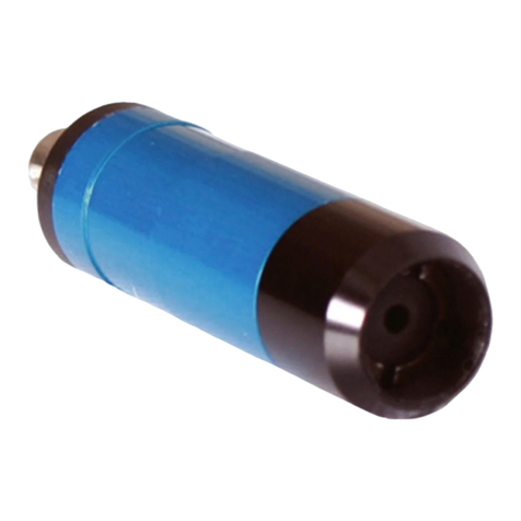
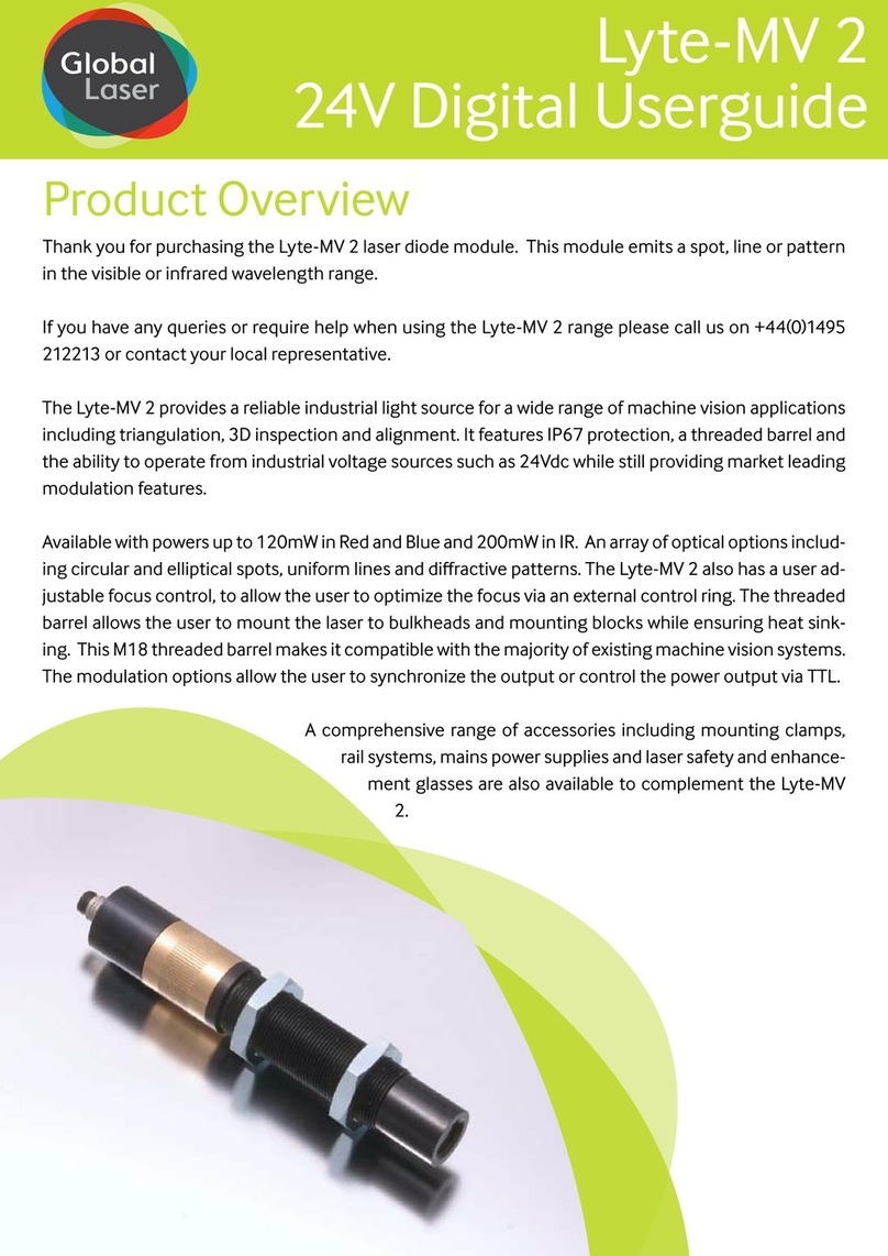
To assist with this requirement the Lyte-MV 2 has a threaded front barrel (M18x1) which can
t to a bulkhead or threaded hole. The direct contact of the barrel to the mount helps to
ensure heat sinking and improve laser diode lifetime. Alternatively a version of Global Laser’s
heavy duty clamp which has a thread arm is available. To further assist mounting the module
is supplied with two nut’s which are tted to the front barrel. A tool to t a 24mm nut is required
for adjustment. To further improve reliability the barrel is isolated from the laser diode supply
voltage at all times.
3A Mounting the Lyte-MV 2 in the Heavy Duty Clamp
1. Un-tighten allen screw A (see drawing B) with the supplied allen key
2. Screw the laser into the mounting hole (see drawing B) and tighten allen key A.
3. For vertical adjustment of the laser un-tighten grub screw A (see drawing B). This will allow
the section mounting the laser to be adjusted. When the vertical posting is complete re-
tighten grub screw A.
4. For horizontal adjustment of the laser un-tighten grub screw B (see drawing B). This will
allow the main body of the mount to be moved. When the horizontal positing is complete re-
tighten grub screw B.
5. To secure the heavy duty clamp to a surface machine screw or studs can be used in
conjunction with the base section (see drawing B for thread details).
3B Mounting the Lyte-MV 2 in the Heavy Duty Clamp with the Magnetic Base
1. Un-tighten allen screw A (see drawing B) with the supplied allen key
2. Screw the laser into the mounting hole (see drawing B) and tighten allen key A.
3. For vertical adjustment of the laser un-tighten grub screw A (see drawing B). This will allow
the section mounting the laser to be adjusted. When the vertical posting is complete re-
tighten grub screw A.
4. For horizontal adjustment of the laser un-tighten grub screw B (see drawing B). This will
allow the main body of the mount to be moved. When the horizontal positing is complete re-
tighten grub screw B.
5. To secure the magnetic base to the heavy duty clamp simple screw the stud on the top of
the magnetic base into the centre hole in the base of the heavy duty clamp until tight.
6. Remove the keeper from the magnetic base and place on a ferrous surface to secure.
3. Mounting
