Global Laser LaserLyte Red User manual

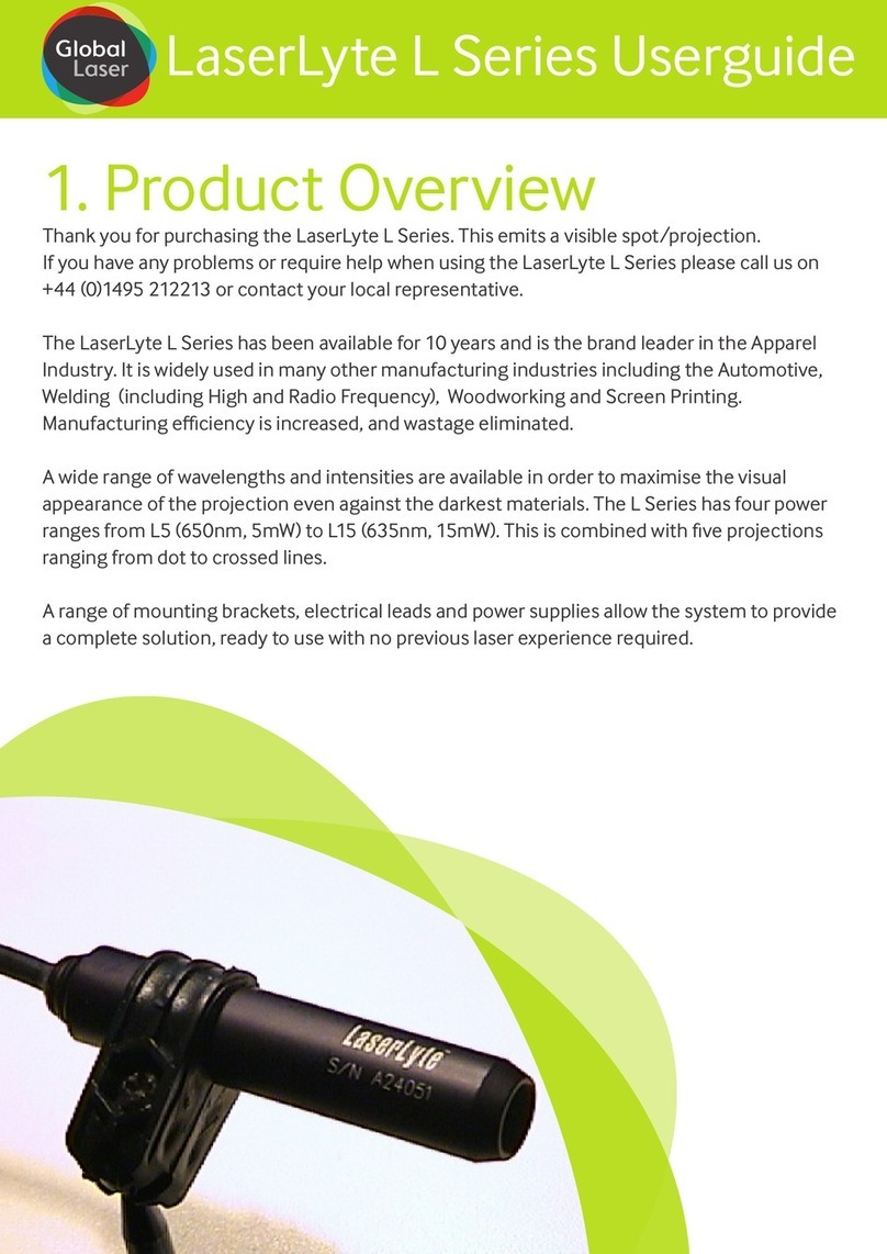
Thank you for purchasing the LaserLyte red laser alignment system. A wide range of wavelengths and
intensities (standard power - 650nm, 5mW to ultra bright - 635nm, 15mW) are available in order to
maximise the visual appearance of the projection even against the darkest materials. This combined
with six projections ranging from dots , lines to crossed lines. A unique focus mechanism also allows
the user to adjust the focus without removing any optics. This helps you to accurately align and
position garments, cloth, paper, wood, and metal of dierent shapes and surface proles.
A range of mounting brackets, electrical leads and power supplies allow the system to provide a
complete solution, ready to use with no previous laser experience required.
This guide explains how to mount and operate your laser, adjust the focus, and change projection
optics. This guide also discusses the relationship between working distance, fan angle, and line length.
If you have any queries or require help when using this product then please call is on +44 (0)1495
212213, email us at sales@globallasertech.com or contact your local representative.
Product Overview
LaserLyte Red Userguide
A Global Laser Brand

Operating LaserLyte With 5V PS1/PS4
Power Supply
Operating LaserLyte With 4.5V Battery
Box
If you have purchased an extension lead:
1. Plug the male DC Jack end of the extension lead into the DC socket on the PS1/PS4
2. Plug the male DC Jack of the LaserLyte cable into the DC socket on the extension lead
If you have not purchased an extension lead:
3. Plug the male DC Jack of the LaserLyte cable directly into the DC socket on the PS1/PS4
If you are using more than one laser with the PS4 then repeat the above steps until all your lasers are
connected.
4. Connect IEC plug to PS1/PS4
5. Plug the PS1/PS4 into a mains socket
6. Switch on PS1/PS4 with the optional key switch or at the mains socket
For further information please refer to the Universal Power Supplies datasheet.
The battery box power supply provides power in applications where it is impractical to use a permanent
power source.
1. Remove the lid of the box by unscrewing 4 x Phillips head screws
2. Insert 3 x industrial AA batteries into battery compartment
3. Replace the lid
4. Plug the DC jack end of the LaserLyte-Flex cable into the DC socket on the battery box
5. Switch on the power supply using onboard rocker switch
For further information please refer to the Battery Box datasheet.
Focus Adjustment
The focus distance of your laser upon delivery will be collimated unless requested otherwise. This can
be adjusted as follows:
1. Insert focus key into focus control hole on laser barrel.
2. Turn until desired focus is achieved (if the key turns to maximum limit re-insert and continue to turn
until focus is achieved).

Manipulating The Pattern
A number of the LaserLyte alignment system modules have user adjustable patterns which are con-
trolled by rotating the front section of the lens assembly by an adjustment pin (as shown in diagram A).
Below is a summary of the futures .
RXL Model: Varies the angle between the crossed line so a 90° cross is achieved at any angle of mount-
ing.
VLL Model: The length of the line can be adjusted between a 30 and 80° fan angle.
VLL+D Model: The length of the line can be adjusted.
Dvi Model: The intensity (brightness) of the dot can be varied.
Xvi Model: The intensity (brightness) of the cross can be varied.
Mounting
The lifetime and stability of your laser can be optimised when mounted on a suitable heat sink. This
allows the case temperature to be kept within its specied range. Failure to properly heat sink your laser
device could result in shortened lifetime or failure of the diode. As a general guideline, the lifetime of a
laser diode decreases by a factor of two (approx.) for every 10°C increase in operating temperature.
There are four mounting clamps available for the LaserLyte: heavy duty clamp (with/without magnetic
base), swivel clamp, MK1 mounting kit and pillow block bearing mount.
Mounting the LaserLyte in the Heavy Duty Clamp (See drawing B)
1. Secure the clamp to a surface. There are two methods:
a. Screw an M5 stud to the bottom of the base, or
b. Remove the base by removing 2 x grub screw B with the supplied Allen key, then thread an M5
cap screw through the top of the base. Then re-attach the base to the body of the clamp.
2. Loosen Allen screw A with the supplied Allen key
3. Slide your laser into the mounting hole and then tighten Allen screw A
4. Loosen grub screw A
5. Adjust the vertical angle of your laser and then tighten grub screw A
6. Loosen 2 x grub screw B. This will allow the main body of the mount to be rotated independently of
the base
7. Adjust the horizontal angle of your laser and then tighten 2 x grub screw B
Mounting the LaserLyte in the Heavy Duty Clamp with Magnetic Base (See drawing B&D)
1. Secure the magnetic base to the Heavy Duty Clamp
a. Screw the stud on the top of the magnetic base into the centre hole at the bottom of the Heavy
Duty Clamp
2. Remove the keeper from the magnetic base and place on a ferrous surface
3. Loosen Allen screw A with the supplied Allen key
4. Slide your laser into the mounting hole and then tighten Allen screw A

5. Loosen grub screw A
6. Adjust the vertical angle of your laser and then tighten grub screw A
7. Loosen 2 x grub screw B. This will allow the main body of the mount to be rotated independently
of the base
8. Adjust the horizontal angle of your laser and then tighten 2 x grub screw B
Mounting the LaserLyte in the Swivel Mounting Clamp (See drawing C)
1. Secure the mounting base to a surface
a. You can use 2 x Ø9 mm slots, 4 x Ø4.5 mm holes, and/or 2 x Ø3.5 mm countersunk holes to
achieve this. If mounting via Ø3.5mm countersunk holes, the swivel bracket must be removed
from the base and then reattached after mounting.
2. Loosen Allen screw A (M3)
3. Slide your laser into the mounting hole and then tighten Allen screw A
4. Loosen Allen screw B (M5)
5. Adjust tilt angle and then tighten Allen screw B
6. Loosen 2 x M4 screws attaching swivel bracket to base
7. Adjust swivel angle and then tighten 2 x M4 screws remains with the user
Mounting the LaserLyte in the MK1 Mounting Kit (See drawing E)
1. Fix the mounting clamp to the mounting surface or bracket using the supplied machine screw A
(both an M5*25 & an M5*35 machine screw and two M5 hex nut & washers are supplied) Tighten with
an Allen key (M3) to lock into position. If you wish to adjust the height of the post slacken machine
screw A and set the height of the mounting post and retighten machine screw A (see drawing B).
2. Un-tighten Phillips screw A (see drawing B) on the laser clamp with a Phillips head screw-
driver.
3. Slide the laser into the mounting hole (see drawing B) and rotate the laser clamp to the de-
sired position and tighten Phillips screw A to lock into position.
Mounting the LaserLyte in the Pillow Block Bearing Mount (See Drawing F)
1. Secure the mount to your workbench or surface using the 20 x 11 mm oval slots in the base
2. Unscrew the M6 or M8 socket head screws to remove the clamp from the base
3. Separate the black mounting cylinder from the spherical rolling element
4. Insert your laser into the mounting cylinder
5. Replace both halves of the spherical rolling element around the cylinder and hold in place
6. Position the spherical rolling element and mounting cylinder in the curved section of the clamp
and hold in place
7. Replace the other half of the clamp and hold in place
8. Screw the M6 or M8 socket head screws through the clamp and into the base
9. Manually adjust the direction of your laser
If you require a longer line then a 80° fan angle will produce at the working distance then a possible
solution may be to change the mounting position and angle of the laser. By moving the laser to end of
the working area and angling the laser to a 50° angle to the work surface the line length is increased by
a factor of 3. See the table below and the diagram for a comparison.
Working Distance (mm) Line Length (mm)
250 1418
500 2836
1000 5671
2500 14178
5000 28356
10000 56713
The size of the fan angle (or spread of the beam) will determine how long the line is. When viewed from
the same distance and at 90° to the surface a line with a fan angle of 80° will be longer then a line with
a fan angle of 30°.
Fan Angle (°)
30 55 90
Distance From Object (mm)
250 134 260 500
Line Length (mm)
500 268 521 1000
750 402 781 1500
1000 536 1041 2000
1250 670 1301 2500
1500 804 1562 3000
1750 938 1822 3500
2000 1072 2082 4000
2250 1206 2343 4500
2500 1340 2603 5000
2750 1474 2863 5500
3000 1608 3123 6000
3250 1742 3384 6500
3500 1876 3644 7000
3750 2010 3904 7500
4000 2144 4165 8000
4250 2278 4425 8500
4500 2412 4685 9000
Fan Angle (°) Distance to
Object (mm)
Line Length
(mm)
30 100 54
80 100 168
As a guide to relationship between working distance, line length and fan angle please see the table
below.
Working Distances

If your product develops a fault within 12 months from the date of purchase Global Laser will repair /
replace the product. If you wish to return a faulty product contact your local representative or Global
Laser to obtain a RMA (Return Material Authorisation code) and return to the address below:
Global Laser Ltd
Units 9-10
Roseheyworth Business Park
Abertillery
Gwent, NP13 1SP
United Kingdom
Warranty & Repair
Safety & Classication
These modules are intended for incorporation into customer equipment. They are classied in
accordance with IEC60825-1 2014, which should be consulted prior to designing or using any laser
product.Thefollowinglabelsaresuppliedforattachmenttothecustomer’sequipment,butresponsibility
for compliance with the standard remains with the user.
Class 2 Laser Label
www.globallasertech.com
IEC 60825-1:2014
LASER RADIATION
DO NOT STARE INTO BEAM
CLASS 2 LASER PRODUCT
<1mW CW 400-695nm
Product Description & Name
Product Code
Serial Number
Product Description & Name
Product Code
Serial Number
Class 3R Laser Label
www.globallasertech.com
IEC 60825-1:2014
LASER RADIATION
AVOID DIRECT EYE EXPOSURE
CLASS 3R LASER PRODUCT
<5mW CW 400-695nm
Product Description & Name
Product Code
Serial Number
Product Description & Name
Product Code
Serial Number
Class 2M Laser Label
www.globallasertech.com
IEC 60825-1:2014
Product Description & Name
Product Code
Serial Number
Product Description & Name
Product Code
Serial Number
LASER RADIATION
DO NOT STARE INTO BEAM OR VIEW
DIRECTLY WITH OPTICAL INSTRUMENTS
CLASS 2M LASER PRODUCT
<1mW CW 400-695nm
Mechanical Dimensions
A) LaserLyte
69.00
Ø14.15
Adjust Collimator Lens through
aperture in module outer case.
Using supplied key.
Jack Plug Power
Connection
DC Power Jack 2.5mm,
Centre Pin: 0 Volts
Outer Pin: +Ve
90°
Turn to adjut
pattern

B) Heavy Duty Mounting Clamp
17.00
8.00
Ø25.00
BOTTOM
SECTION
SIDE VIEW
Tap M5 x 6 Deep
BOTTOM SECTION
B OTTOM VIEW
1 Hole Drill 4.2Ø & C/Bore 7.5Ø x 5 Deep
at One End and Tap M5 x 6 Deep at The
Other End
BOTTOM SECTION
TO P VIEW
30.00
Ø19.00
45.00
Ø25.00
35.00
48.00
SIDE VIEW TOP VIEW
Grub Screw A (M5)
Allen Screw A (M5)
Heavy Duty Mounting Clamp For 11, 14, 15mm Lasers
Grub Screw A (M5)
Ø14mm (1240-02-000)
C) Swivel Mounting Clamp
SIDE VIEW
12.70
40.00
45.00
40.00
FRONT VIEW
22.00
M3 x 6
5.00
Allen Screw A (M3)
Allen Screw B (M5)
MOUNTING
BASE SIDE
5.00
MOUNTING
BASE
50.00
25.00
20.00
20.00
10.00 10.00
3.508.00
40.00
20.00
14.00
14.00
12.00
4 Holes 4.50 Diameter
2 Slots Ø9.00
2 Holes drill Ø4.50 and counterbore
Hex Hole to suit M4 MS full nuts at rear
2 Holes Ø3.50 and
countersunk to suit
M3 Ct/Sunk screws
Ø14mm (1200-04-000)

9090-02-063 Rev 4 18/07/2022
T: +44 (0)1495 212213
F:+44 (0)1495 214004
E: sales@globallasertech.com
www.globallasertech.com
Global Laser Ltd
Units 9-10
Roseheyworth Business Park
Abertillery. Gwent NP13 1SP UK
Please Note: Global Laser reserve the right to change
descriptions and specications without notice.
Manufacturing
Operations Certied
to ISO9001
F) Pillow Block Bearing Mount Ø14mm
50.00
20.00
11.00 10.00 34.00
16.00
13.00
20.00
37.00
2 Off Socket Head Screws M6 x 35 Long
102.00
130.00
20.00
11.00 14.00 40.00
50.00
16.00
20.00
2 Off Socket Head Cap Screws M8 x 40LG
2 Off M8 Full Nuts
37.00
102.00
130.00
20.00
11.00 12.50 48.00
72.00
18.00
20.00
2 Off M8 Cap Head Scres x 50 Long
54.00
102.00
130.00
32.50
64.00
6.35
M5 Nut
12.70
24.70
12.70
M5 x 25/35 C/sk
socket screw
(Machine Screw A)
SIDE VIEW
FRONT VIEW
6x32 un 5/8” Phillips screw and
6x32 unc hex nut (Phillips screw A)
E) MK1 Mounting Clamp
30.00
Ø35.00
FRONT VIEW
6.00
M6 Stud
TOP VIEW
M6 Stud
Ø35.00
D) Magnetic Base
Table of contents
Other Global Laser Measuring Instrument manuals

Global Laser
Global Laser BlueLyte LC User manual

Global Laser
Global Laser LaserLyte L Series User manual

Global Laser
Global Laser LDM127 User manual

Global Laser
Global Laser LaserLyte User manual

Global Laser
Global Laser Lyte-MV 2 User manual

Global Laser
Global Laser Lyte-MV 2 User manual

Global Laser
Global Laser GreenLyte-MV Excel User manual
Popular Measuring Instrument manuals by other brands

SEFRAM
SEFRAM 9835 instruction manual

Commtest Instruments
Commtest Instruments vbBalancer Instrument Reference Guide

Elma
Elma Laser X360 Series manual

Kamstrup
Kamstrup MULTICAL 602 Installation and user guide

Keysight
Keysight N9021B MXA Installation notes

Fuji Electric
Fuji Electric ZPAF instruction manual