Global Laser BlueLyte LC User manual

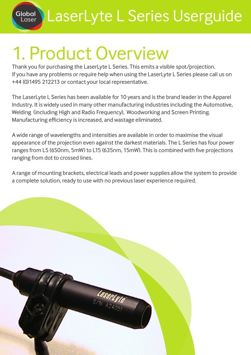
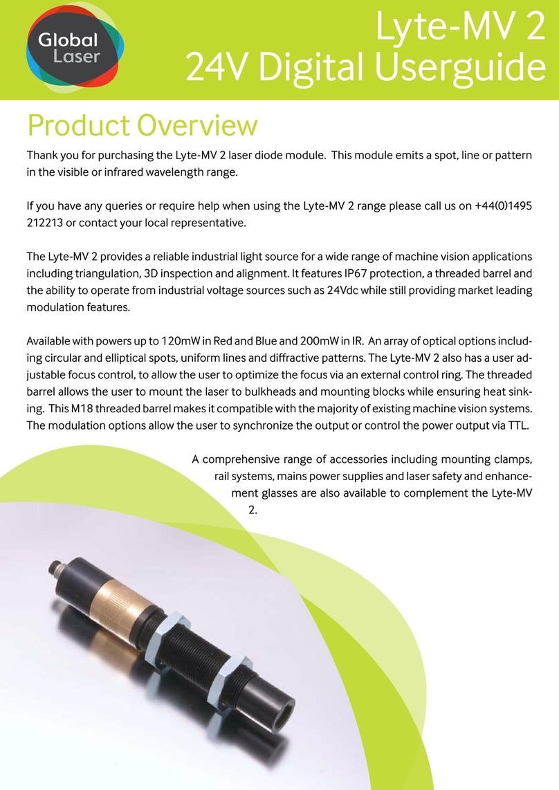
Thank you for purchasing the BlueLyte LC laser. This laser emits a Blue / Violet spot/
projection.
If you have any queries or require help when using the BlueLyte LC range please call us on
+44(0)1495 212213 or contact your local representative.
Stable output power is oered over a wide temperature range with the additional benet of a LC
(Linear Control) control circuit. The LC control circuit allows you to control the output intensity
linearly by applying a voltage of between 0 & 1 volt, to the control input. This same control
circuit also provides analogue modulation with modulation speeds in excess of 500kHz The
output intensity will faithfully replicate any arbitrary signal you wish to apply with a 0-1 Volt
amplitude and within the limits of the laser module’s maximum rise and fall time.
Further exibility is provided by a choice of collimating lens providing circular or elliptical beams.
The user adjustable collimating lens allows simple adjustment to provide a collimated beam or
a focused spot at a required distance. A wide range of line generators and projection patterns
are also available.
A wide range of output powers is available which combined
with the compact 15mm diameter housing with a robust
industrial connector and choice of optional mounting
clamps provides a complete blue laser
solution.
1. Product Overview
BlueLyte LC Userguide

2. Production Operation
A: CW Mode
To operate the laser in CW mode the Red, Black, Yellow and Blue Leads should be connected to
the following:
1. Red Lead: +8Vdc ±500mV
2. Black Lead: 0Vdc
3. Yellow Lead: Not connected
4. Blue Lead: V supply if not using as enable switch
B: Linear Modulation Control Function
To linearly modulate the laser, any modulation signal up to 700kHz (dependant on diode) with
an amplitude of 0V to +1Vdc can be applied to the yellow lead.
1. Red Lead: +8Vdc ±500mV
2. Black Lead: 0Vdc
3. Yellow Lead: input modulation signal 0 to +1Vdc amplitude
4. Blue Lead: V supply if not using as enable switch
C. Setting Power Via a Voltage
Alternatively the yellow lead can be used for a linear power control function. In this situation,
the laser power is denoted by a voltage applied to the yellow Lead, 0V turning the laser o and
+1Vdc giving maximum power, with linear trend between. See linear intensity graph .
1. Red Lead: +8Vdc ±500mV
2. Black Lead: 0Vdc
3. Yellow Lead: input control voltage (0 to +1Vdc)
4. Blue Lead: V supply if not using as enable switch
0.0 0.2 0.4 0.6 0.8 1.0
0
20
5
40
60
80
100
Control Voltage (Vdc)
Output Power (%)
D) Setting the Output Power Via a Resistor
The control wire has a 10k Ohm input impedance
connected to an internal 1V source which is used as
the reference for the factory set power. Measuring
the voltage between the Yellow and Black wires with
a high (>10M Ohm) impedance voltmeter, will give a
reading of 1 V ± 2%. Connecting a 10k Ohm resistance
between the Yellow and Black wires will result in the
reading falling to 0.5V and the light output falling to
half the factory set power. Other outputs between 0
and the factory set power can be achieved with a single resistor Rx by using the formula:
Where Po is the required power output
as Pfs is the factory set power
RX = Po* 10K
PFs - Po

Blue Lead (Enable Switch)
An on/o switch function is available via the blue wire. Applying 0V will switch the laser o
whilst applying Vsupply leaves the laser on. This is partially useful for safety interlocks or
enable switch’s required for laser safety systems. A TTL switch can also be utilised via this
lead. TTL High = on and TTL Low = o. Maximum frequency is typically 100 hz. If not using
these function please connect the lead to the V supply or the laser will not switch on.
3. Focus Adjustment
The focus of the laser can be adjusted by using the supplied focus key. Should you need to
adjust the focus please follow the instructions below.
1. Remove any external optics, where tted (see diagram B).
2. Insert focus key into laser barrel and align with focus control groves.
3. Turn the focus key until desired focus is achieved.
4. Replace the external optics if tted and rotate to achieve the desired projection.
4. Cleaning The Optics
It is recommended that when the BlueLyte LC laser in not in use the supplied protective cap is
placed over the optics to reduce the risk of being contaminate by dirt.
If the laser pattern becomes fuzzy or unclear, please check the following:
1. Check the laser is in focus (see section 3).
2. Verify the optical lens is clean, if the area has been please remove any dirt with dry air.

5. Mounting & Heatsinking
To ensure the lifetime and the stability of the laser it is recommended that it is mounted in a
suitable heat sink/mount. The case temperature should be kept within the specied range at
all times, failure to do this could result in shortened lifetime or catastrophic failure. As a guide,
laser diode lifetime decreases by a factor of two (approx) for every ten degree increase in
operating temperature.
There are two mounting clamps available as standard from Global Laser for the BlueLyte LC
laser. Global Laser’s Heavy Duty Clamp has parallel and vertical adjustment which allows the
user to aim the laser in any required direction or angle, the robust aluminium construction
also assists in conducting heat away from the laser body as well as prevents movement due
to shock and vibration. The base plate of the Heavy Duty Clamp has a series of threaded holes
to allow the Heavy Duty Clamp to be securely fastened to stable surface An Magnetic base is
also available which simply screws in to the base of the Heavy Duty Clamp and allow it to be
tted to a ferrous surface.
The swivel mount is available for BlueLyte LC laser. It provides the user with up and down tilt
movement as well as +/- 45° swivel. The base plate has a series of holes which allows the
clamp to be xed directly onto a machine or workbench. On the rear of the main block are
two M3 threaded holes which enable heatsink ns to be attached if required.
5A Mounting the BlueLyte LC laser in the Heavy Duty Clamp
1. Un-tighten Allen screw A (see drawing 7C) with the supplied Allen key.
2. Slide the laser into the mounting hole (see drawing 7C) and tighten Allen key A.
3. For vertical adjustment of the laser un-tighten Grub screw A (see drawing 7C). This will
allow the section mounting the laser to be adjusted. When the vertical posting is complete
re-tighten grub screw A.
4. For horizontal adjustment of the laser un-tighten Grub screw B (see drawing 7C). This will
allow the main body of the mount to be moved. When the horizontal positing is complete
re-tighten grub screw B.
5. To secure the Heavy Duty Clamp to a surface machine screw or studs can be used in
conjunction with the base section (see drawing 7C for thread details) .

5B Mounting the BlueLyte LC Laser in the Heavy Duty Clamp with the Magnetic Base
1. Un-tighten Allen screw A (see drawing 7C) with the supplied Allen key
2. Slide the laser into the mounting hole (see drawing 7C) and tighten Allen key A.
3. For vertical adjustment of the laser un-tighten Grub screw A (see drawing 7C). This will
allow the section mounting the laser to be adjusted. When the vertical posting is complete
re-tighten grub screw A.
4. For horizontal adjustment of the laser un-tighten Grub screw B (see drawing 7C). This will
allow the main body of the mount to be moved. When the horizontal positing is complete
re-tighten grub screw B.
5. To secure the magnetic base to the Heavy Duty Clamp simple screw the stud on the top
of the magnetic base into the centre hole in the base of the Heavy Duty Clamp until tight.
6. Remove the keeper from the magnetic base and place on a ferrous surface to secure.
5C Mounting the BlueLyte LC laser in the Swivel Mount
1. Un-tighten Allen screw A (see drawing 7E).
2 Slide the laser into the mounting hole (see drawing 7E) and tighten Allen key A.
3. For vertical adjustment of the laser un-tighten allen screw B (see drawing 7E). This will
allow the section mounting the laser to be adjusted. When the vertical posting is complete
re-tighten Allen screw B.
4. For horizontal adjustment of the laser un-tighten Allen screw C (see drawing 7E). This will
allow the main body of the mount to be moved. When the horizontal positing is complete
re-tighten Allen screw C.
5. To secure the swivel mount to a surface screws, machine screw can be used in
conjunction with the base section (see drawing 7E for thread details).
6. Safety & Classication
These modules are intended for incorporation into customer equipment. They are classied
in accordance with IEC60825-1 2007, which should be consulted prior to designing or using
any laser product. The following labels are supplied for attachment to the customer’s
equipment, but responsibility for compliance with the standard remains with the user.
Class 3B Laser Label Class 3R Laser Label
IEC 60825 Warning Labels (examples)
www.globallasertech.com
IEC 60825-1:2007
LASER RADIATION
AVOID EXPOSURE TO BEAM
CLASS 3B LASER PRODUCT
<500mW CW 400-695nm
Product Description & Name
Product Co de
Serial Number
Product Description & Name
Product Code
Serial Number
www.globallasertech.com
IEC 60825-1:2007
LASER RADIATION
AVOID DIRECT EYE EXPOSURE
CLASS 3R LASER PRODUCT
<5mW CW 400-695nm
Product Description & Name
Product Co de
Serial Number
Product Description & Name
Product Code
Serial Number

7. Diagrams
Drawings are not to scale.
6. Warranty & Repair
If your product develops a fault within 12 months from the date of purchase Global Laser
will repair / replace the product. If you wish to return a faulty product contact your local
representative or Global Laser to obtain a RMA (Return Material Authorisation code) and
return to the address below:
Global Laser Ltd
Unit 9-10
Roseheyworth Business Park
Abertillery
Gwent, NP13 1SP
United Kingdom
A) BlueLyte LC
B) BlueLyte LC with External Optics
Ø15.00
Ø14.90
47.15
46.85
Total Length Depends on Focus Position
Ø15.00
Ø14.90
47.15
46.85

E) Swivel Mounting Clamp
SIDE VIEW
MOUNTIN G
BASE
FRONT VIE W
MOUNTIN G
BASE SIDE
12.70
40.00
45.00
50.00
22.00
Ø15.20
Ø15.10
5.00
50.00
25.00
20.00
20.00
10.00 10.00
3.50
8.00
40.00
20.00
14.00
14.00
12.00
4 Holes 4.50 Diameter
2 Slots Ø9.00
2 Holes drill Ø4.50 and counter-
bore Hex Hole to suit M4 MS full
nuts at rear
2 Holes Ø3.50 and
countersunk to suit
M3 Ct/Sunk screws
5.00
Allen Screw A (M3)
Allen Screw B (M5)
Drawings are not to scale.
C) Heavy Duty Mounting Clamp D) Magnetic Clamp
45mm
25mm ø
19mm ø
M5 Mounting hole on base
30.00
Ø35.00
FRONT VIEW
6.00
M6 Stud
TOP VIEW
M6 Stud
Ø35.00

T: +44 (0)1495 212213
F:+44 (0)1495 214004
E: sales@globallasertech.com
www.globallasertech.com
Global Laser Ltd
Units 9-10
Roseheyworth Business Park
Abertillery. Gwent NP13 1SP UK
For further information about any of our products please contact
your local distributor or you can contact Global Laser in the UK. Your
Local Distributor Is:
ISO9001 Certied
Please note: Global Laser reserve the right to change descriptions
and specications without notice.
8. Notes
9090-02-043 Rev 2 07/05/2013
Table of contents
Other Global Laser Measuring Instrument manuals

Global Laser
Global Laser Lyte-MV 2 User manual

Global Laser
Global Laser Lyte-MV 2 User manual

Global Laser
Global Laser GreenLyte-MV Excel User manual

Global Laser
Global Laser LaserLyte Red User manual

Global Laser
Global Laser LDM127 User manual

Global Laser
Global Laser LaserLyte L Series User manual

Global Laser
Global Laser LaserLyte User manual