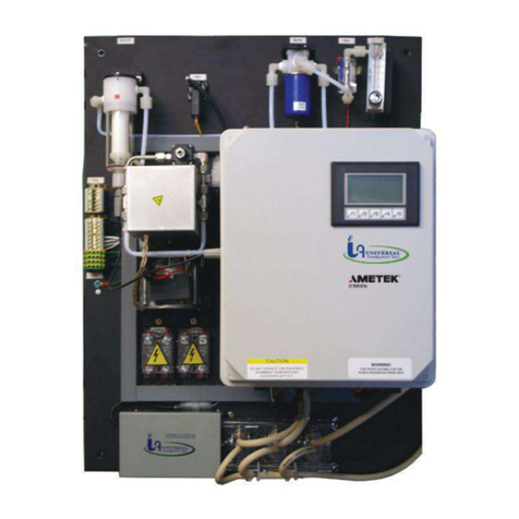
Universal Analyzers SCP User manual

MAN.SCPSCU.REVD.03022015
Instruction Manual
Models SCP and SCU
Sample Conditioning Plate
5200 Convair Drive Carson City, NV 89706 • Phone: 775-883-2500 • Fax: 775-883-6388 • www.universalanalyzers.com

Page 2 of 43 Page 3 of 43
MAN.SCPSCU.REVD.03022015
Contents
Receiving and Storage 3
Denition of Symbols 4
Specications 5
Description and Principle of Operation 6
Installation 8
Electrical Connections 9
Process and Piping Connections 10
Start-Up 13
Shutdown 13
Maintenance 14
Troubleshooting 16
Spare Parts 17
Drawings 19
Limited Warranty 41

Page 2 of 43 Page 3 of 43 MAN.SCPSCU.REVD.03022015
Receiving and Storage
The Universal Analyzers Models SCP and SCU Sample Conditioning Systems are complete assemblies. No assembly is
necessary when received on-site.
Carefully inspect the product and any special accessories included with it immediately on arrival by removing them from
the packing and checking for missing components against the packing list.
Check the items for any damage in transit and, if required, inform the shipping insurance company immediately of any
damage found.
Storage Location should be protected from the elements. Although all components provided are designed to resist
corrosion, additional protection from heat (>140°F/ 60°C) and humidity is recommended.

Page 4 of 43 Page 5 of 43
MAN.SCPSCU.REVD.03022015
Denition of Symbols
WARNING - EXPLOSION HAZARD - DO NOT DISCONNECT EQUIPMENT UNLESS POWER HAS BEEN SWITCHED
OFF OR THE AREA IS KNOWN TO BE NON-HAZARDOUS.
WARNING - EXPLOSION HAZARD - SAMPLE CONDITIONING SYSTEMS SCP OR SCU ARE NOT SUITABLE FOR
HAZARDOUS AREA INSTALLATION.
THE SUPPLY POWER CIRCUIT MUST INCLUDE AN OVERPROTECTION DEVICE WITH A MAXIMUM RATING OF 20
A. A DISCONNECT SWITCH MUST BE LOCATED IN CLOSE PROXIMITY TO THE SAMPLE CONDITIONING SYSTEM.
IF THE EQUIPMENT IS USED IN A MANNER NOT SPECIFIED BY THE MANUFACTURER, THE PROTECTION
PROVIDED BY THE EQUIPMENT MAY BE IMPAIRED PER CLAUSE 5.4.4(i) IN STANDARD EN 61010-1.
CAUTION, RISK OF DANGER SYMBOL INDICATES INJURY MAY OCCUR IF MANUFACTURER’S INSTRUCTIONS
ARE NOT ADHERED TO. PLEASE READ MANUAL CAREFULLY WHEN SYMBOL IS DISPLAYED.
CAUTION, HOT SURFACE SYMBOL INDICATES EXPOSED SURFACE TEMPERATURE CAN CAUSE BURNS OR
PERSONAL INJURY. CARE SHOULD BE TAKEN WHEN CONTACT IS REQUIRED.
CAUTION, RISK OF ELECTRICAL SHOCK SYMBOL INDICATES ELECTRICAL SHOCK MAY OCCUR. CAUTION
SHOULD BE TAKEN BEFORE DISCONNECTING OR CONTACTING ANY ELECTRICAL CONNECTIONS.
PROTECTIVE CONDUCTOR TERMINAL SYMBOL INDICATES THE TERMINAL LOCATION FOR THE
PROTECTIVE CONDUCTOR. FAILURE TO CONNECT TO THE PROTECTIVE CONDUCTOR TERMINAL MAY RESULT
IN A SHOCK HAZARD.

Page 4 of 43 Page 5 of 43 MAN.SCPSCU.REVD.03022015
Specications
OPERATING SPECIFICATIONS
Sample Flow Rate 0 to 8 l/m **
Maximum Inlet Temperature
Stainless Steel Heat Exchanger 700°F (370°C)
Kynar/Glass Heat Exchanger 280°F (138°C)
Maximum Inlet Gas Dew Point 194°F (90°C)*
Maximum Inlet Water Vapor Content 70%*
Minimum Ambient Temperature 34°F (0°C)
Maximum Ambient Temperature 105°F (41°C)*
Maximum Cooling Power (Second Stage) 252 BTUs per hour (240 kJ/Hr)
Outlet Sample Dew Point 39°F (4°C)
Maximum Input Power 75-700 Watts***
Voltage 95-125VAC 50/60 Hz or
190-250VAC 50/60 Hz
(External fuse required or 20A or less)
Electrical Classication General Purpose
Temperature Classication FM/CSA T3A, ATEX 143°C (T3)
SCP Dimensions 38 1/2" H x 20 3/4" W
SCU Dimensions 31" H x 19" W x 12" D
Weight 75 lbs (34kg)
Soluble Gas Removal Rates NO 0% loss
NO2<10% loss
SO2< 2% loss
CO 0% loss
CO2< 2% loss
*AT REDUCED FLOW RATE ABOVE 77°F. (25°C.) AMBIENT.
**SEE GAS COOLER CAPACITY CHART BELOW.
***WATTAGE DEPENDANT ON SELECTED COOLER. CONTACT FACTORY FOR SELECTED COOLER WATTAGE.
3000 SERIES - COOLER CAPACITY DATA
Ambient 77°F/25°C
Water Vapor
Ambient 90°F/25°C
Water Vapor
Ambient 105°F/25°C
Water Vapor
12% 15% 30% 50% 12% 15% 30% 50% 12% 15% 30% 50%
3040 5 l/m 4 l/m 2.8 l/m 1.4 l/m 5 l/m 4 l/m 2 l/m 1 l/m 2.8 l/m 2.4 l/m 1.2 l/m 0.6 lm
3050 8 l/m 8 l/m 7 l/m 6 l/m 6 l/m 6 l/m 5.5 lm 4.5 l/m 3 l/m 3 l/m 2.5 l/m 2 l/m
3080 10 l/m 8 l/m 4 l/m 2 l/m 8 l/m 7 l/m 3.5 l/m 1.8 l/m 4.6 l/m 4 l/m 2.2 l/m 1.1 l/m
600 SERIES - COOLER CAPACITY DATA
Ambient 77°F/25°C
Water Vapor
Ambient 90°F/25°C
Water Vapor
Ambient 105°F/25°C
Water Vapor
12% 15% 30% 50% 12% 15% 30% 50% 12% 15% 30% 50%
620 2.5 l/m 2 l/m 1 l/m 0.6 l/m 2 l/m 1.8 l/m 0.9 l/m 0.5 l/m 1.5 l/m 1.2 l/m 0.6 l/m 0.3 lm
630 4 l/m 4 l/m 4 l/m 4 l/m 3 l/m 3 l/m 3 lm 3 l/m 2 l/m 2 l/m 2 l/m 2 l/m
640 5 l/m 4 l/m 2 l/m 1 l/m 4 l/m 3.5 l/m 1.8 l/m 0.9 l/m 3 l/m 2.5 l/m 1.3 l/m 0.7 l/m
(Flow Rate, Water Vapor % and the Ambient Temperature are the three main factors to consider when sizing a gas cooler.)

Page 6 of 43 Page 7 of 43
MAN.SCPSCU.REVD.03022015
Description and Principle of Operation
APPLICATION
In order to analyze combustion products or incinerator efuents utilizing a direct extractive sampling technique, it is
important to remove the water vapor without removing the water soluble fraction(s) from the gas sample. The heat
exchangers (impingers) used in the Universal Analyzers gas sample coolers are designed to minimize the gas/condensate
area and time of contact to reduce to a minimum, the amount of mass transfer of those water soluble components from
the gas phase into the liquid phase. The result is a dry gas sample which has the same composition on a dry basis before
and after passing through the chiller.
A gas sample is usually taken from a stack with a probe extending into the stack. The heated probe lter is maintained at
a temperature above the dew point of the stack gas, usually 300°F to 400°F (149°C to 204°C), in order to avoid cementing
the ltered particulates to the lter medium with condensate. A means is usually provided to automatically blow the
particulates trapped by the lter back into the stack on a periodic basis.
The stack gas sample is clean but “wet” after passing through the lter assembly. The moisture in the gas sample comes
from the fuel as a product of combustion, from the humidity in the air which supports the combustion and from the water
content which was trapped in the fuel. This latter source of water in the sample can be from burning moist coal, wet
garbage, or from water injected into the re box. Water from all of these sources will remove the water soluble gases
from the sample stream if allowed to condense in the sample line prior to the controlled separation within the Universal
Analyzers’ heat exchangers in the sample cooler.
In order to maintain the temperature of the gas sample above the dew point as it is transported to the gas sample cooler,
a heat traced sample line is usually employed. The heat traced sample line can be very short if the gas sample cooler is
located close to the heated stack lter or it could be several hundred feet long if the gas sample cooler is located in the
analyzer shack some distance from the stack.
The Universal Analyzers gas sample cooler contains the special impinger type heat exchanger(s). These are mounted
within heat transfer blocks which are cooled by thermoelectric elements utilizing the “Peltier Effect” discovered in
France over half a century ago. Where high water contents are encountered, it is efcient to remove the condensate
in two stages, one at the temperature of the air in the vicinity of the “Precooler” and then by passing the sample into
a heat exchanger cooled by the thermoelectric elements. The precooler can remove water which will condense at the
temperature of the environment. In high water content samples, this could be as much as 80% of the water in the sample.
The thermo-electrically cooled stage is temperature controlled at a factory setting of 4°C (39°F).
The gas sample conditioning system contains additional components to insure that a clean, dry sample is presented to the
analyzer for minimum analyzer maintenance. The water carry over sensor with lter (WCSF) provides the opportunity to
detect if moisture has traveled past the cooler and alarms to indicate a problem with a part of the sample system (possibly,
but not limited to the cooler). The WCSF consists of a coalescing lter (ceramic standard), transparent bowl, and
capacitance sensor. The capacitive sensor allows for detection of any liquid or solid that has passed into the transparent
bowl, including distilled water with no ions present.
DESCRIPTION
The key to the success of the Universal Analyzers Sample Cooler is being able to condense the water from a wet gas
sample with a minimal loss of the water soluble gas fraction is due to the design of the heat exchanger. Please refer to
Drawings P0147 and P0149. The separation occurs in a classical impinger which has a highly polished cylindrical surface
cooled to the desired dew point temperature. The hot wet sample is brought to the bottom of the cylinder through an
insulated tube and allowed to rise through a narrow annular area at a relatively high Reynolds number to insure the entire
sample is inuenced by the cold surface. The condensate falls down the cold polished surface in the form of a sheet
(as opposed to droplets or the bubbling of the gas sample through the condensate) which minimizes the surface area in
contact with the gas sample.

Page 6 of 43 Page 7 of 43 MAN.SCPSCU.REVD.03022015
Description and Principle of Operation
The temperature of the cylindrical condensation surface of the heat exchanger is maintained through intimate contact with
an aluminum heat transfer block. The heat transfer block is cooled by direct contact with the heat sink which is cooled by
the blower or fan, model dependent. The temperature of the rst of the two heat exchangers will be about 10°F. above the
temperature of the air passing through the heat sink. (The temperature differential depends on the amount of heat that is
being extracted from the sample, which is a function of the water content of the sample.)
The second of the heat exchangers through which the sample passes is cooled by the use of Thermoelectric Elements
at a controlled temperature. The factory temperature setting is 4°C. The temperature sensor is an AD592 semiconductor
device. The controller is a proportional controller with a proportional band of about 1°C.
The heat which is removed from the gas sample (and that which is created by the Thermoelectric Elements) is discharged
by a heat sink which is cooled with a centrifugal drum blower or fan. The heat sinks are fabricated from solid blocks of
aluminum which eliminates the epoxy joints in more conventional heat sink designs which are barriers to heat conduction.
The result is a heat removal system with superior performance under all conditions.
Universal Analyzers Thermoelectric Sample Coolers have a digital display as a front panel indication of the operating
temperature (in degrees C) of the heat exchangers. In addition, there are two LED lamps to indicate the status of the
cooler. The “COOL” lamp lights when the operating temperature is between 0°C and 10°C (32° and 50°F). If the operating
temperature is above or below this range, the light will be out and the alarm relay will be in the alarm position. The “DRY”
lamp indicates that there is no water in contact with the moisture sensor listed as WCSF. If the “DRY” lamp is out, the
alarm relay will be in the alarm position.
The alarm relay is a single relay activated by either of the above alarm conditions. The alarm relay is energized in the
“safe” condition and will relax into the de-energized, alarm position if a fault is detected. If a broken AD592 occurs, the
result will be that the temperature indication is out of range and the alarm relay will indicate a fault.
A thermal switch is mounted on the heat sink to serve as a safety device to turn off power to the thermoelectric elements
if the heat sink approaches 185°F (85°C). This protects the thermoelectric elements from failing in the event high
temperature conditions are encountered for any reason.
The SCP and SCU thermoelectric sample systems are designed with an incorporated peristaltic pump for condensate
removal.
Finally, a means of controlling the ow of the sample to the analyzers must be considered. This can be as simple as a
ow meter with a ow control needle valve to pinch off the sample ow causing the sample pump to pump higher on the
pump curve. The provided adjustable back-pressure regulator between the inlet and outlet of the sample pump to allow
a portion of the gas pumped to be recirculated back to the inlet if discharge pressure exceeds the back-pressure control
point. Some analyzers have their own sample pump which may be sufcient to supply the analyzer but insufcient to pull
the sample through the chiller, sample line, and heated stack lter. These can be supplied by piping the sample from the
external sample pump into the run of a tee with a ow meter which registers the ow of excess sample from the branch
of the tee to atmosphere. The internal analyzer sample pump can then withdraw sample from the opposite run of the tee
which is essentially at atmospheric pressure and unaffected by pressure changes within the sample line due to changes in
lter pressure drop or sample pump efciency.

Page 8 of 43 Page 9 of 43
MAN.SCPSCU.REVD.03022015
Installation
THE SUPPLY POWER CIRCUIT MUST INCLUDE AN OVERPROTECTION DEVICE WITH A MAXIMUM
RATING OF 20 A. A DISCONNECT SWITCH MUST BE LOCATED IN CLOSE PROXIMITY TO THE
COOLER. IF THE EQUIPMENT IS USED IN A MANNER NOT SPECIFIED BY THE MANUFACTURER,
THE PROTECTION PROVIDED BY THE EQUIPMENT MAY BE IMPAIRED PER CLAUSE 5.4.4(I) IN
STANDARD EN 61010-1.
Installation shall be in accord with the facility requirements. Tampering and replacement with non-factory components
may adversely affect the safe use of the system.
Thermoelectric Sample Coolers should be installed away from heat sources in a well ventilated area of an instrument
rack or enclosure. The Cooler relies on the ambient temperature as a coolant, too high a level will cause it to perform
unreliably. Contact the factory for recommendations.
The sample has mounting taps on the top and bottom to allow it to be wall mounted or mounted to rails in an instrument
rack.
Sample line should be brought to the tubing tting that is provided at the top of the rst heat exchanger as the sample
inlet. The dry sample outlet from the cooler is the 1/4” tubing tting coming out of the top of the ow meters located at
the top of the panel.
Calibration gas connections are 1/4" tube ttings located at the manifold at the top of the sample conditioning panel.
Calibration gas out connection to probe lter is located on the ow meter panel.
All ow meter connections are 1/4" tube ttings.
The drain connection is a 3/8" tube tting located at the bottom of the sample conditioning panel. Moisture should be
observed at the drain from the cooler when a steady state condition is established.
There must be a method to remove the condensate from the panel. A drain line from the peristaltic pump, outlet must be
run to sewer, a container, or to the ground outside the instrument enclosure to avoid collecting water (condensate) on
the oor.

Page 8 of 43 Page 9 of 43 MAN.SCPSCU.REVD.03022015
Electrical Connections
3000 Series, Models SCP and SCU
1
2
3
G
TB3
HP/S1 - TB1-1
P/S1 - TB1-3
N
G
115 / 230 VAC 10A
POWER INPUT P/S1 - TB1-2
SAMPLE COOLER
POWER SUPPLY
BOARD
(P/S1)
P/N: 5209-0048
PELTIERS
1
2
34
115V 230V
JUMPER CARD
1 RED
2
1 HOT L1
2 COM L2
3
TB3
TB1
TB2
W
C
O
1 N.C.
2
3 N.O.
DRY CIRC
4 N.C
5
6 N.O.
A
L
A
R
M
R
E
L
A
Y
MOV PROT
SEE NOTE 1
BLOWER
J3
DRAIN
J1
H
N
G
H
N
G
SAMPLE
J2
H
N
G
CONTACTS PROTECTED
WITH 250 VOLT MOV'S
12-AMP F.A. FUSE
P/N: 3010-0006
6-AMP S.B. FUSE
P/N: 3010-0005
BLK BLOWER
P/S1 J3 BLOWER-P4-WHT
P/S1+ RED
P/S1- BLK 1
2
3+
4
240V
10A
3-32VDC
SSR1
P/N: 3152-0002
BLOWER CONTROL
3-32VDC CONTROL
10AMP
WHT BLOWER
P/S1 J7-2
P/S1 J7-1 1
2
3+
4
240V
25A
3-32VDC
SSR2
P/N: 3152-0002
P1-PUMP CONTROL
3-32VDC CONTROL
25AMP
PELTIER 1
PELTIER 2
RED
BLK
RED
BLK
+
-
+
-
+
-
+
-
H
N
G
P/S1 DRAIN-P2
P/S1 DRAIN-P1
P/S1 DRAIN-P3
P2
DRAIN PUMP
SSR1-2
SSR1-2
P/S1 BLOWER-P3
P/S1 BLOWER-P5
P/S1 BLOWER-P1
BLOWER
(C/CARD)
P/N 3600-0012
DISPLAY/CONTROL
CARD
PELTIERS
P/N: 3016-0001
2
1
3
P
P
3
5
1
4
BLU
RED
GRN
WHT
BLK
J7
SSR2-1
TB4-2
TB4-G
4
3
1
P
SSR1-1
P/S1 J2 SAMPLE-P4
TB4-1
COOLER MODELS
3040
3050
3080
2
1
3
4
5
6
7
VIKING
CONNECTOR
J6
RED
BLK
RED
BLK
SSR1-4
RED
BLK
RED
BLK
185°F
NO
CNO
P/N 3103-0006
AD592
P/N 1150-0017
SSR2-3
SSR2-4
SSR1-3
TB2-1
TB2-2
TB3-1
TB3-3
TB3-G
G
CONDUIT AND WIRING NOTES
1. ELECTRICAL CLASSIFICATION : INSIDE - GENERAL PURPOSE
SYSTEM IS CONFIGURED AT THE FACTORY FOR REQUIRED VOLTAGE.
CONTACT FACTORY FOR VOLTAGE CHANGE REQUIREMENTS.
2. AC WIRING SHALL BE INDIVIDUAL CONDUCTORS OF STRANDED TINNED
COPPER WITH 300V, TYPE TFE INSULATION. MINIMUM WIRE SIZE SHALL BE
18 AWG UNLESS OTHERWISE SPECIFIED.
COLOR CODE SHALL BE AS FOLLOWS:
115VAC 230VAC
HOT - BLACK L1 - BROWN
NEUTRAL - WHITE L2 - BLUE
GROUND - GREEN G - GREEN
3. DC WIRING SHALL BE INDIVIDUAL CONDUCTORS OF STRANDED TINNED
COPPER WITH 300V, TYPE TFE INSULATION. MINIMUM WIRE SIZE SHALL BE
22 AWG UNLESS OTHERWISE SPECIFIED.
115VAC 230VAC
COLOR CODE SHALL BE AS FOLOOWS: +V - RED +VDC - RED
0V - BLUE -VDC - BLACK
FIELD TO WIRE
G
2
1
TB4
SSR2-2
PS/1 J2 SAMPLE P3
PS/2 J2 SAMPLE P1
H
N
G
P1
SAMPLE
PUMP
WCOF
REV
REVISIONS
FORPART NO. M. Walser
APVD BY
DRAWN BY DRAWING NO.
DATE
Wiring Schematic
DATE DESCRIPTION DWN APVD
SCALE SIZE SHEET
NTS D 5 OF 5
ECO#
P2011
09/18/2013
3000 Series
3000-SCP-INT
3000 Series
- 09/18/13 Initial Release MY MW
1801M. Withrow
4
TB5-11
TB6-2
TB5-2
TB5-9
TB5-7
TB5-5
TB5-3
TB5-1
TB6-5
TB6-3
TB6-1
14
TB1
13
12
11
10
9
8
7
6
5
4
3
2
1
SV1
SV2
SV3
SV4
SV5
SV6
SV7
SV8
SOLENOID VALVE POWER
+24VDC
SV9
P1
EXTERNAL SUPPLY
+
-
24VDC
CHILLER MALFUNCTION
VACUUM SWITCH
PRESSURE SWITCH
CALIBRATION PRESSURE SWITCH
P/S1 TB2-6
P/S1 TB2-5
PS2-NO
PS2-C
VS1-NC
VS1-C
10
TB2
9
8
7
6
5
4
3
2
1
PS1-NO
PS1-C
C
NC
C
NO
C
NO
C
NO
TB5
1
2
3
4
5
6
SV4 +
SV5 +
SV6 +
SV4 -
SV5 -
SV6 -
TB1-5
TB1-12
TB1-6
TB1-7
+-
SV4
SV5
SV6
SV7
SV8
SV9
TB5-1 TB5-2
TB5-3 TB5-4
TB5-5 TB5-6
TB5-7 TB5-8
TB5-9 TB5-10
TB5-11 TB5-12
7
8
9
10
11
12
SV7 +
SV8 +
SV9 +
SV7 -
SV8 -
SV9 -
TB1-8
TB1-9
TB1-10
24VDC SOLENOIDS
CALIBRATION GASES
+-
+-
+-
+-
+-
TB6
+-
+-
+-
SV1
SV2
SV3
1
2
3
4
5
6
SV1 +
SV2 +
SV3 +
SV1 -
SV2 -
SV3 -
TB1-2
TB1-12
TB1-3
TB1-4
TB6-1 TB6-2
TB6-3 TB6-4
TB6-5 TB6-6
24VDC SOLENOIDS
SWITCHING BLOCK
OPTIONAL
PELTIER 1
PELTIER 2
RED
BLK
RED
BLK
CH1
(3040 & 3050)
PELTIERS
P/N: 3016-0001
CH2
(3080)
TB2-8TB2-7
TB2-4
TB2-3
PS2
CAL. GAS PRESSURE
VS1
INLET VACUUM
NO
NC
C
NC
NOC
TB2-6
TB2-5
PS1
SAMPLE OUTLET PRESSURE
NO
NC
C
5200 Convair Drive Carson City, NV 89706 PH(775)883-2500 FAX (775)883-6388

Page 10 of 43 Page 11 of 43
MAN.SCPSCU.REVD.03022015
Electrical Connections
600 Series, Models SCP and SCU
H
N
G
115 / 230 VAC 10A
POWER INPUT
CONDUIT AND WIRING NOTES
1. ELECTRICAL CLASSIFICATION : INSIDE - GENERAL PURPOSE
SYSTEM IS CONFIGURED AT THE FACTORY FOR REQUIRED VOLTAGE.
CONTACT FACTORY FOR VOLTAGE CHANGE REQUIREMENTS.
2. AC WIRING SHALL BE INDIVIDUAL CONDUCTORS OF STRANDED TINNED
COPPER WITH 300V, TYPE TFE INSULATION. MINIMUM WIRE SIZE SHALL BE
18 AWG UNLESS OTHERWISE SPECIFIED.
COLOR CODE SHALL BE AS FOLLOWS:
115VAC 230VAC
HOT - BLACK L1 - BROWN
NEUTRAL - WHITE L2 - BLUE
GROUND - GREEN G - GREEN
3. DC WIRING SHALL BE INDIVIDUAL CONDUCTORS OF STRANDED TINNED
COPPER WITH 300V, TYPE TFE INSULATION. MINIMUM WIRE SIZE SHALL BE
22 AWG UNLESS OTHERWISE SPECIFIED.
115VAC 230VAC
COLOR CODE SHALL BE AS FOLOOWS: +V - RED +VDC - RED
0V - BLUE -VDC - BLACK
POWER PLUG POLARITY =
FIELD TO WIRE
REV
REVISIONS
FORPART NO. M. Walser
APVD BY
DRAWN BY DRAWING NO.
DATE
Wiring Schematic
DATE DESCRIPTION DWN APVD
SCALE SIZE SHEET
NTS D 5 OF 5
ECO#
09/18/2013
- 09/18/13 Initial Release MY MW
1801M. Withrow
C/CARD TB2-2
TB5-11
TB5-2
TB4-2
TB5-9
TB5-7
TB5-5
TB5-3
TB5-1
TB4-5
TB4-3
TB4-1
14
TB1
13
12
11
10
9
8
7
6
5
4
3
2
1SAMPLE PUMP
SV1
SV2
SV3
SV4
SV5
SV6
SV7
SV8
SOLENOID VALVE POWER
+24VDC
SV9
50 WATTS
P1
EXTERNAL SUPPLY
+24VDC
+
-
24VDC
CHILLER MALFUNCTION
VACUUM SWITCH
PRESSURE SWITCH
CALIBRATION PRESSURE SWITCH
C/CARD TB3-1
C/CARD TB3-2
PS2-NO
PS2-C
VS1-NC
VS1-C
10
TB2
9
8
7
6
5
4
3
2
1
PS1-NO
PS1-C
C
NC
C
NO
C
NO
C
NO
TB5
1
2
3
4
5
6
SV4 +
SV5 +
SV6 +
SV4 -
SV5 -
SV6 -
TB1-5
TB1-12
TB1-6
TB1-7
+-
SV4
SV5
SV6
SV7
SV8
SV9
TB5-1 TB5-2
TB5-3 TB5-4
TB5-5 TB5-6
TB5-7 TB5-8
TB5-9 TB5-10
TB5-11 TB5-12
7
8
9
10
11
12
SV7 +
SV8 +
SV9 +
SV7 -
SV8 -
SV9 -
TB1-8
TB1-9
TB1-10
24VDC SOLENOIDS
CALIBRATION GASES
+-
+-
+-
+-
+-
TB4
+-
+-
+-
SV1
SV2
SV3
1
2
3
4
5
6
SV1 +
SV2 +
SV3 +
SV1 -
SV2 -
SV3 -
TB1-2
TB1-12
TB1-3
TB1-4
TB4-1 TB4-2
TB4-3 TB4-4
TB4-5 TB4-6
SSR1-4
24VDC SOLENOIDS
SWITCHING BLOCK
OPTIONAL
TB2-8TB2-7
TB2-4
TB2-3
PS2
CAL. GAS PRESSURE
VS1
INLET VACUUM
NO
NC
C
NC
NOC
TB2-6
TB2-5
PS1
SAMPLE OUTLET PRESSURE
NO
NC
C
P2012
600 Series
600-SCP-INT
600 Series
1
2
3
4
TB4
TB1
1
2
3
4
5
6
+
+
-
+
-
-
COM TP
GREEN LED - DRY
TEMP SET TP
YELLOW LED - COOLING
RAW TEMP TP
WCO
(J9)
AD592
(J1)
OVER TEMP
(J10)
WET
DRY
C
WET
DRY
C
1
2
3
1
2
3
TB2
TB3
CHILLER CONTROLLER CARD
C/CARD
MOISTURE
SENSOR
1-A
AD592
FAN -V
FAN +V
1-B
P/S +V
P/S -V
C/CARD (RED)
C/CARD (BLK)
C/CARD (RED)
C/CARD (BLK)
J7
1-A (BLK)
TB2-2
DIGITAL TEMP. DISPLAY
D/D
D/D V- (BLU)
D/D V+ (RED)
D/D INLO (YEL/ORG)
D/D INHI (YEL/BRN)
V-
V+
INHI
INLO
CHILLER
C/CARD TB4-2 (YEL/ORG)
C/CARD TB4-1 (YEL/BRN)
C/CARD TB4-3 (RED)
P/N 1150-0017
J6 1-B
C/CARD TB4-4 (BLUE)
SSR1-3
TB1-1
TEMP. POINT
ADJUST POINT
P/N 5209-1009
4
P/N 0320-1000
COOLER MODELS
624
634
644
OPTIONAL
TB3
1
2
3
4
G
GP/S1-G
P/S1-H
P2-N
P/S1-N
P1-G
P1-N
624
634
644
644
TB2-1
4
TB3-2
P2-H
TB3-G
TB3-4
SSR 1-1
TB3-G
TB3-4
SSR 1-1
TB2-1 C/CARD
P1-H
SEE NOTE #1
PERISTALTIC PUMP P2
SEE NOTE #1
SAMPLE PUMP P1
G
N
H
G
N
H
1
23
4
SSR1
P/N: 3152-0002
PUMP CONTROL
3 - 32VDC CONTROL
25AMP
240V 25A
3 - 32 VDC
TB4-6
+
-
-+
J3
J2
J5 1-B
J4 1-A
PELTIER WIRING
6 X 4 (24Vdc)
PELTIER 1 PELTIER 2
(+) - J4 (+) -J6
(-) - J3 (-) - J5
SSR1-2
P2-G
L N
- V - V +V +V
AC
DC
P/S1
POWER SUPPLY
320WATT 24VDC
P/N 5400-0009
TB1-1
TB1-3
TB1-G
C-CARD TB1-1
C-CARD TB1-2
5200 Convair Drive Carson City, NV 89706 PH(775)883-2500 FAX (775)883-6388

Page 10 of 43 Page 11 of 43 MAN.SCPSCU.REVD.03022015
Process Piping and Connections
3000 Series, Models SCP and SCU
PLC OR DATA LOGGER
1) CALIBRATION/SAMPLE SELECT
2) CALIBRATION GAS SELECT
3) SYSTEM/DIRECT CALIBRATION SELECT-SYSTEM BIAS CALCULATION
4) PROBE BLOW BACK
5) PROBE LOW TEMPERATURE ALARM
6) CHILLER MALFUNCTION-HIGH TEMPERATURE OR WATER CARRY-OVER
7) HIGH INLET VACUUM - PROBE FILTER INITIATE BLOWBACK OR MAINTENANCE
8) SAMPLE/CALIB. GAS PRESS LOW-ALARM FOR MANTENANCE
Item Qty Description UAI Part No.
VS1
WCOF
PI-1
SPC1
P1
P1
PS1,2
SV1,3
SV2
SV4-9
PI-2
SYS CAL
FM1-4
FM5
CHILLER
CHILLER
R1
S) (
P2
P2
Vacuum Switch Air-Logic 0-29"hg
Water Carry Over Moisture Sensor
Gauge - Vacuum 0-30"Hg Liquid Filled S.S.
Sample Pressure Controller
Pump - Sample 115Vac Single Head
Pump - Sample 230Vac Single Head
Pressure Switch Air-Logic F-5100-15 15psig
Solenoid Valve - Burkert 6012SER
Solenoid Valve - Burkert 6011SER 85psig
Solenoid Valve 2 Way
Gauge - Pressure 0-15psig Liquid Filled S.S.
Flowmeter W/Needle Valve 0-10 l/m
Flowmeter W/Needle Valve 0-2.5 l/m
Flowmeter W/Needle Valve 0-5 l/m
Universal Analyzers Model 3050
Universal Analizers Model 3050
Regulator - Porter Model #8268 0-30psig
Snubber - #6-32
Pump - Peristaltic Drain 115Vac
Pump - Peristaltic Drain 230Vac
3103-0017
WCOF-4980-0007
3019-0009
4955-0246
4958-0025
4958-0015
3103-0018
4955-0041
4955-0040
4955-0247
3019-0008
4965-0007
4965-0018
4965-0008
3050 - 115Vac
3050 - 230Vac
8200-0008
0000-0000
4958-0028
4958-0045
1
1
1
1
1
1
2
2
1
2-6
1
1
4
1
1
1
1
1
1
1
CALIBRATION GASES - 6 MAXIMUM
CALIB GAS
TO PROBE
STACK FLOW
CG1
SV4
FI
0-2.5 L/MIN
SAMPLE TO ANALYZER
INSTR AIR @ <90 PSIG
-40°F. DEWPOINT
CALIB GAS
SAMPLE
SV2 SV3
SV1
GAS BLOCK & BLEED
3-WAY SOLENOID
PRESSURE
SAMPLE/CALIB
PI-2
VACCUM
PUMP
PI-1
SYSTEM CALIBRATION
2-WAY SOLENOID
CALIBRATION
SAMPLE/DIRECT
3-WAY SOLENOID
0-10 L/MIN
FI
CG2 CG3 CG4
CALIBRATION
GAS SELECTION
BY PLC
CALIB/SAMPLE
SELECTION BY
PLC
PROBE BLOW BACK
& LOW TEMPERATURE ALARM
WCOF
SPC1
SET @ 10PSIG
HIGH VACUUM
LOW SAMPLE/CALIB.
GAS PRESS.
CHILLER MALFUNCTION
HIGH TEMPERATURE
OR WATER CARRY-OVER
CALIBRATION GAS
PRESSURE REGULATOR
SAMPLE CONDITIONING PLATE
SAMPLE
FLOWMETERS
AIT
VENT
4-20MA
4-20MA
AIT OUTPUT
VOLTAGE/CURRENT
PLC
PRESSURE SWITCH
LOSS CALIB. GAS
0-2.5 L/MIN
FI
FI
FI
0-5 L/MIN
CHANNELS
#1
VS1
PS1
SET @ 5 psi
PS2
LIQUID
DRAIN
1(P) 2(A)
FM1
FM2
FM3
FM5
SV5 SV6 SV7
SYS
CAL
R1
P2
INLET
3/8" TUBE
S
SNUBBER
S
SNUBBER
SET @ 5psi
SET @ 10psi
SET @ 7hg
REV
REVISIONS
FORPART NO. M. Walser
APVD BY
DRAWN BY DRAWING NO.
DATE
P&ID
DATE DESCRIPTION DWN APVD
SCALE SIZE SHEET
NTS D 3 OF 5
ECO#
3 WAY VALVE
TYPICAL
NC
C
NO
LEGEND
2 WAY
NORMALLY CLOSED
NOTES:
1. ALL FITTINGS 1/4" TUBE (UNLESS OTHERWISE NOTED).
BULKHEAD FITTING
FOR REFERENCE ONLY
PI
4-20MA
0-2.5 L/MIN
BYPASS
#2
#3
#5
P1
PI
AIT
AIT
P2011
09/18/2013
3000 Series
3000-SCP-INT
- 09/18/13 Initial Release MY MW
1801M. Withrow
BLEED
OUT
4-20MA
FI
FM4
0-2.5 L/MIN
#4 AIT
OPTIONAL
OPTIONAL
CG5 CG6
SV8 SV9
Model SCP W/ 3050
5200 Convair Drive Carson City, NV 89706 PH(775)883-2500 FAX (775)883-6388

Page 12 of 43 Page 13 of 43
MAN.SCPSCU.REVD.03022015
Process Piping and Connections
600 Series, Models SCP and SCU
PLC OR DATA LOGGER
1) CALIBRATION/SAMPLE SELECT
2) CALIBRATION GAS SELECT
3) SYSTEM/DIRECT CALIBRATION SELECT-SYSTEM BIAS CALCULATION
4) PROBE BLOW BACK
5) PROBE LOW TEMPERATURE ALARM
6) CHILLER MALFUNCTION-HIGH TEMPERATURE OR WATER CARRY-OVER
7) HIGH INLET VACUUM - PROBE FILTER INITIATE BLOWBACK OR MAINTENANCE
8) SAMPLE/CALIB. GAS PRESS LOW-ALARM FOR MANTENANCE
CALIBRATION GASES - 6 MAXIMUM
CALIB GAS
TO PROBE
STACK FLOW
CG1
SV4
FI
0-2.5 L/MIN
SAMPLE TO ANALYZER
INSTR AIR @ <90 PSIG
-40°F. DEWPOINT
CALIB GAS
SAMPLE
SV2 SV3
SV1
GAS BLOCK & BLEED
3-WAY SOLENOID
PRESSURE
SAMPLE/CALIB
PI-2
VACCUM
PUMP
PI-1
SYSTEM CALIBRATION
2-WAY SOLENOID
CALIBRATION
SAMPLE/DIRECT
3-WAY SOLENOID
0-10 L/MIN
FI
CG2 CG3 CG4
CALIBRATION
GAS SELECTION
BY PLC
CALIB/SAMPLE
SELECTION BY
PLC
PROBE BLOW BACK
& LOW TEMPERATURE ALARM
WCOF
SPC1
SET @ 10PSIG
HIGH VACUUM
LOW SAMPLE/CALIB.
GAS PRESS.
CHILLER MALFUNCTION
HIGH TEMPERATURE
OR WATER CARRY-OVER
CALIBRATION GAS
PRESSURE REGULATOR
SAMPLE CONDITIONING PLATE
SAMPLE
FLOWMETERS
AIT
VENT
4-20MA
AIT OUTPUT
VOLTAGE/CURRENT
PLC
PRESSURE SWITCH
LOSS CALIB. GAS
0-2.5 L/MIN
FI
FI
0-5 L/MIN
CHANNELS
#1
VS1
PS1
SET @ 5 psi
PS2
LIQUID
DRAIN
1(P) 2(A)
FM1
FM2
SV5 SV6 SV7
SYS
CAL
R1
P2
INLET
3/8" TUBE
S
SNUBBER
S
SNUBBER
SET @ 5psi
SET @ 10psi
SET @ 7hg
REV
REVISIONS
FORPART NO. M. Walser
APVD BY
DRAWN BY DRAWING NO.
DATE
P&ID
DATE DESCRIPTION DWN APVD
SCALE SIZE SHEET
NTS D 3 OF 5
ECO#
3 WAY VALVE
TYPICAL
NC
C
NO
LEGEND
2 WAY
NORMALLY CLOSED
NOTES:
1. ALL FITTINGS 1/4" TUBE (UNLESS OTHERWISE NOTED).
BULKHEAD FITTING
FOR REFERENCE ONLY
PI
4-20MA
BYPASS
#2
#5
P1
PI
AIT
09/18/2013
- 09/18/13 Initial Release MY MW
1801M. Withrow
BLEED
OUT
OPTIONAL
OPTIONAL
CG5 CG6
SV8 SV9
P2012
600 Series
600-SCP-INT
Item Qty Description UAI Part No.
VS1
WCOF
PI-1
SPC1
P1
P1
PS1,2
SV1,3
SV2
SV4-9
PI-2
SYS CAL
FM1-4
FM5
CHILLER
R1
S) (
P2
P2
Vacuum Switch Air-Logic 0-29"hg
Water Carry Over Moisture Sensor
Gauge - Vacuum 0-30"Hg Liquid Filled S.S.
Sample Pressure Controller
Pump - Sample 115Vac Single Head
Pump - Sample 230Vac Single Head
Pressure Switch Air-Logic F-5100-15 15psig
Solenoid Valve-Burkert 6012SER
Solenoid Valve-Burkert 6011SER 85psig
Solenoid Valve-Asco
Gauge - Pressure 0-15psig Liquid Filled S.S.
Flowmeter W/Needle Valve 0-10 l/m
Flowmeter W/Needle Valve 0-2.5 l/m
Flowmeter W/Needle Valve 0-5 l/m
Universal Analyzers Model 634
Regulator - Porter Model #8268 0-30psig
Snubber - #6-32
Pump - Peristaltic Drain 115Vac Dual Head
Pump - Peristaltic Drain 230Vac Dual Head
3103-0017
WCOF-4980-0007
3019-0009
4955-0246
4958-0025
4958-0015
3103-0018
4955-0041
4955-0040
4955-0247
3019-0008
4965-0007
4965-0018
4965-0008
634
8200-0008
0000-0000
4958-0012
4958-0035
1
1
1
1
1
1
2
2
1
2-6
1
1
4
1
1
1
1
1
1
Model SCP W/ 634
FM5
0-2.5 L/MIN
FI
FM3
4-20MA
#2 AIT
5200 Convair Drive Carson City, NV 89706 PH(775)883-2500 FAX (775)883-6388

Page 12 of 43 Page 13 of 43 MAN.SCPSCU.REVD.03022015
Start-Up
NOTE: IT IS IMPORTANT THAT THE HEATED PROBE AND HEATED SAMPLE LINE SHOULD BE AT
OPERATING TEMPERATURE BEFORE STARTING THE CHILLER AND SAMPLE PUMP.
Apply power to the sample conditioning plate or U-bracket. The indicated temperature will start to drop immediately. It
should be below the over-temperature alarm point in approximately four minutes and the “COOL” green LED lamp should
light. When the temperature reaches the control set point, the rate at which the temperature drops will be reduced. The
temperature will stabilize within 1°C of the control set point.
Once the cooler temperature has been reduced to approximately 10°C to 9°C the sample pump will start. Factory
setting of the ow rate is 10 PSIG at mid scale of combined ow meters going to the analyzers. Each ow meter has
an adjustable valve to provide a ow rate as needed for each of the individual sample output. If additional or reduced
pressure is required there is an adjustable pressure regulator located at the pump.
The green “DRY” LED light will be on at start-up. The light will go out and the alarm relay de-energized when the sensor
detects condensate. A test can be performed by putting water on the moisture sensor. The sample pump is powered
through the alarm relay contacts, it will cease running. When the moisture sensor is wiped dry, the sample pump will start.
Turn on the analyzer(s) and initiate the calibration cycle.
Shutdown
Before removing power from the unit, ensure the system has been purged of any potentially hazardous components.
To purge the system, perform the following:
1. Perform a manual blowback operation.
2. If feasible, provide instrument air to the prove via a cal gas line. If not, disconnect the sample line.
3. Allow the system to run for at least 10 minutes to remove remaining condensate from heat exchangers.
4. Once purging is complete disconnect the sample outlet tube connections and disconnect power from the unit.
Note: If electrical wires are to be disconnected, follow applicable 'Lock Out/Tag Out" requirements.

Page 14 of 43 Page 15 of 43
MAN.SCPSCU.REVD.03022015
Maintenance
Before performing any maintenance on the cooler, ensure that all plant safety procedures are followed. As with any
electrical device, ensure power is removed before performing any procedures.
The cooler is designed for maintenance free operation but if any is required, ensure power has been removed before
maintenance or repair is performed.
For the best performance of the cooler, the following maintenance schedule is recommended:
Maintenance Activity Frequency
Peristaltic pump Replace tubing every 3 months
Diaphragm sample pump Replace diaphragm every 6 months
Clean heat exchanger Annually
Inspect heat sink ns Monthly
MAINTENANCE PROCEDURES
REPLACEMENT OF PERISTALTIC TUBING (IF EQUIPPED)
1. Please refer to manufacturers website for instructions: bit.ly/1zfmrzt
2. YouTube: bit.ly/1MPLUJO
REPLACEMENT OF SAMPLE PUMP DIAPHRAGM
1. Please refer to manufactures website for instructions: http://www.airdimensions.com
INSTALLING OR REPLACING HEAT EXCHANGERS
REMOVING THE HEAT EXCHANGER
1. Remove the inlet and outlet tubes by loosening the compression ttings. Always use a backup wrench on the tting
body to ensure no damage to the heat exchanger occurs.
2. Remove the drain tting using the same procedure as the inlet/ outlet. Remove the drain ttings from the exchanger.
Use a backup wrench on the lower heat exchanger hex to prevent damage to the exchanger.
REPLACING THE HEAT EXCHANGER
1. Dry and clean the heat exchanger opening in the heat transfer block using a dry, lint-free cloth (If reusing the heat
exchanger, clean the outside as well.) Dried heat transfer paste can be removed by using a very ne abrasive pad
wrapped around a drill bit.
2. Smear the outer diameter of the heat exchanger with heat transfer paste.
3. Gently push the heat exchanger into the heat transfer block until the head is fully seated against the insulation on top.
4. Reinstall the drain tting. Ensure pipe tape is used on the pipe threads before installation. Use a backup wrench on
the heat exchanger lower hex to prevent damage to the exchanger.
5. Reconnect the drain, inlet and outlet tubes.

Page 14 of 43 Page 15 of 43 MAN.SCPSCU.REVD.03022015
Maintenance
MAINTENANCE SCHEDULE
The cooler heat sink is used to dissipate heat away from the heat transfer block/ Peltier elements. Over time in an
industrial environment, dust/ debris can build up between the ns on the back side of the heat sink. This build will reduce
the efciency of the cooler and can cause premature failure of the Peltier elements.
INSPECT HEAT SINK FINS
Using a ash light (or other light source), shine a light through the heat sink ns. If the ns are unobstructed, you should
be able to see the aluminum blower ns. If the blower is not visible or partial obstruction exists, clean the heat sink ns.
CLEAN HEAT SINK FINS
Access to the left side of the cooler is required.
First, remove the side panel from the unit. Remove the screws securing the side panel. Once the panel is loose,
disconnect all electrical connectors from the power supply board.
Looking in from the left side, the blower assembly should be visible at the rear of the enclosure. Immediately in front
of the blower is the inlet side of the heat sink. Using a soft bristled brush, gently remove to debris from the heat sink.
Alternatively, a computer safe aerosol cleaner can be used to remove the debris.
Clean any loose debris from the enclosure and blower motor using a vacuum or compressed air. Replace all
connectors, reference electrical drawings below for details. Reinstall the side pane.
CLEANING INSTRUCTIONS
Should the Heat Exchangers require cleaning, disconnect the tubing and remove the Exchangers from the Heat Transfer
Blocks. Wipe off the white heat sink compound with a clean rag. Disassemble the Exchanger. Refer to Drawing Numbers
P0147 through P0149 for an illustration on the assembly of the exchanger. Wipe off all surfaces with a clean rag.
STAINLESS STEEL EXCHANGER (IF REQUIRED)
a) Soak in soap and water solution, or
b) Soak in Solvent such as MEK, Acetone, etc. or
c) Soak in a 10% HNO3solution
PV (GLASS & KYNAR) (IF REQUIRED)
a) Soak in Alcohol to remove hydrocarbons
DO NOT USE MEK, ACETONE OR SIMILAR SOLVENTS ON PV EXCHANGERS
Re-assemble Exchangers with new O-Ring(s). Apply an even coat of Heat Sink Paste to the exterior of the exchanger
tube only. Re-install into Heat Transfer Block and reconnect tubing.

Page 16 of 43 Page 17 of 43
MAN.SCPSCU.REVD.03022015
Troubleshooting
The following table should give an overview of possible errors and an instruction to check and to repair them (is not valid
for the starting-up period of cooler).
Error Possible reason Check/Repair
No sample gas ow Heat exchanger plugged
Alarm pump shutoff
No power on cooler
Check for an obstruction
Remove heat exchanger from unit and
disassemble
Verify cool & dry indicators are illuminated
Ensure cooler has power supplied
Water carry over Inadequate drain apparatus
Excessive ow rate
High ambient temperature
Defective cooler fan or blower
Verify drain tubing is unobstructed and
equipment is functioning satisfactory
Reduce the ow rate
Reduce the ambient temperature (Increase
ventilation or relocate cooler)
Verify air ow across the heat sink
Hold hand in front of heat sink ns and
ensure air movement
High oxygen readings/low
pollutant readings
Leak Loose connection
Verify all ttings are leak free
Defective peristaltic pump tubing
Replace tubing
Broken or leaking heat exchanger
Remove heat exchanger and replace if
broken or repair (replace O-Ring) if leaking
‘Dry’ light is not Illuminated Water carry over
Faulty water carry over device or
circuit board
See “Water Carry Over’ error
Disconnect/ Unplug the 2 wire cable from
the WCO terminals, located on the power
supply board. If the dry light does not illumi-
nate, consult the factory
‘Cool’ light is not illuminated Ambient temperature too high
Flow rate/water content too high
Failed peltier element
Reduce the ambient temperature (Increase
ventilation or relocate cooler)
Lower the ow rate through the cooler and
observe the results. If condition corrects
itself, consult the factory for further
troubleshooting
Measure resistance between the red &
black peltier leads. A failed peltier element
will read high resistance or ‘Open’. Consult
wiring diagram for wire location details

Page 16 of 43 Page 17 of 43 MAN.SCPSCU.REVD.03022015
Spare Parts
3000 Series
Consumable Parts
Part P/N
Peristaltic Pump Tubing, #15, 5' length 9216-0002
6 Amp Slow Blow Fuse for 3000 Series Power Supply 3010-0005
12 Amp Fast Acting Fuse for 3000 Series Power Supply 3010-0006
Basic Parts
Part P/N
Heat Exchanger/Impinger - 316SS 10" 5200-S010
Heat Exchanger/Impinger - Glass/Kynar 10" 5200-K010
Glass Tube, Outer - Heat Exchanger Replacement 10" 5201-0001
O-Ring, 316SS Heat Exchanger - Viton 2-021 4904-0013
O-Ring, Glass/Kynar Heat Exchanger - Viton 2-018 4904-0003
O-Ring, Glass/Kynar Heat Exchanger - Viton 2-120 4904-0004
Paste, Heat Sinking - 0.1 Ounce Container 8010-0001
Critical Parts
Part P/N
Peltier Element, Pair - 15VDC 8.5 Amp 40mm Sq. 3016-0002
Temperature Limit Switch, 185ºF 3103-0006
Solid State Relay, 3-32VDC / 240VAC 10 Amp (Blower Motor) 3152-0004
Power Supply Board - 15VDC 500 Watt 3600-0011
Controller Circuit Board 3600-0012
Peristaltic Pump Head, #15 4958-0006
Peristaltic Pump Motor, 115VAC 6 RPM 4958-0028
Peristaltic Pump Motor, 230VAC 12 RPM 4958-0045
Blower & Motor - Squirrel Cage 115VAC 5209-0049
Blower & Motor - Squirrel Cage 230VAC 5209-0099
Insulation Kit - Heat Transfer Block (Model 3040 & 3050) 9515-0042
Insulation Kit - Heat Transfer Block (Model 3080) 9515-0023
Temperature Sensor Assembly, AD592 1150-0017
Optional Parts/Accessories
Part P/N
Solid State Relay, 3-32VDC / 240VAC 25 Amp (Sample Pump) 3152-0002
WCOF Assembly - Moisture Sensor/2 μm Ceramic Filter WCOF-4980 0007
O-Ring, WCOF Bowl - Viton 2-030 4904-0006
Sample Pump - 115VAC Mini Dia-VAC Alum/Teon Single Head 4958-0025
Sample Pump - 230VAC Mini Dia-VAC Alum/Teon Single Head 4958-0015
Sample Pump - 115VAC Mini Dia-VAC Alum/Teon Dual Head 4958-0026
Sample Pump - 230VAC Mini Dia-VAC Alum/Teon Dual Head 4958-0016
Sample 1 Head Teon coated Aluminum/FM 115V Class I, Div. 2 Approved 4958-1025
Sample Pump Rebuild Kit - Mini Dia-VAC (for Single Head) 9515-0018
Sample Pressure Control 3-36 psig Adjustable 4955-0246
Filter Element - 2 μm Ceramic (WCOF) 4980-0007
Thermocouple Kit, Heat Exchanger - “New Jersey” Type “K” 9515-0046
Thermocouple Kit, Heat Exchanger - “New Jersey” Type “J” 9515-0047
Thermocouple Kit, Heat Exchanger - “New Jersey” Type “T” 9515-0048

Page 18 of 43 Page 19 of 43
MAN.SCPSCU.REVD.03022015
Spare Parts
600 Series
Consumable Parts
Part P/N
Filter Element - 2 mm Ceramic 4980-0007
ADI Mini Dia-VAC Sample Pump Rebuild Kit 9515-0018
Peristaltic Pump Tubing, #15, 5' length 9216-0002
Heat Sink Paste, 0.1 ounce Container 8010-0001
Ceramic Filter Element, 2 µm 4980-0007
Basic Parts
Part P/N
Glass/Kynar Heat Exchanger/Impinger, 5" 5200-K050
316SS, Heat Exchanger/Impinger, 5" 5200-S050
Glass Tube, Outer - Replacement for 5" Heat Exchanger 5201-0002
O-Ring, 2-018, Viton, Glass Heat Exchanger, Bottom 4904-0003
O-Ring, 2-120, Viton, Glass Heat Exchanger, Top 4904-0004
O-Ring, 2-030, Viton, Filter Bowl Seal 4904-0006
O-Ring, 2-021, Viton, 316SS Heat Exchanger 4904-0013
Critical Parts
Part P/N
Peltier Element, Pair - 15VDC 8.5 Amp 40mm (Models 622, 632, 643, 644) 3016-0001
Peltier Element, Pair - 15VDC 3.9 Amp 30mm (Models 624 & 634 Only) 3016-0003
Insulation Kit for Heat Transfer Block 9515-0024
Temperature Sensor, AD592 (Chiller Control) 1150-0017
Temperature Switch, Limit 185°F (Over Temp) 3103-0006
Heat Sink Cooling Fan, 12VDC 4800-0002
Heat Sink Cooling Fan, 24VDC 4800-0008
Optional Parts/Accessories
Part P/N
Power Supply, 12VDC, 156 Watt 5400-1015
Power Supply, 24VDC, 300 Watt 5400-0007
Controller/Alarm Circuit Board, 600 Series, 12VDC 3600-0035
Controller/Alarm Circuit Board, 600 Series, 15-24VDC 3600-0036
Single Head Sample Pump, TFE/AI Head, Mini Dia-VAC 4958-0025
Dual Head Sample Pump, TFE/AI Head, Mini Dia-VAC 4958-0026
Back Pressure Regulator, Plastic Adjustable PSIG, Sample Pump 4955-0246
Peristaltic Pump Motor, 120VAC with Chassis 4958-0003
Peristaltic Pump Head for #15 Tubing 4958-0006
WCOF Moisture Sensor Bowl Assembly 5205-0038

Page 18 of 43 Page 19 of 43 MAN.SCPSCU.REVD.03022015
Drawings
600 Series, Model SCP
FRONT VIEW
PS1
PS2
VS1
SSR1
TB1
TB2
TB4
TB3
TB5
R1
B&B
P2012
09/18/2013
600 Series
REV
REVISIONS
FORPART NO. M. Walser
APVD BY
DRAWN BY DRAWING NO.
DATE
600-SCP-INT
Model 600 Series
Layout & Dimensions
DATE DESCRIPTION DWN APVD
SCALE SIZE SHEET
NTS D 1 OF 5
- 09/18/13 Initial Release MY MW
ECO#
1801
ISOMETRIC VIEW
P1
P2
WCOF
M. Withrow
PI-1 PI-2
MODEL
600
CG1 2 3 4 5 6 SYS
CAL FM1 FM2 FM3 FM4
SPC1
20 3/4"
38 1/2"
19 1/8"
36 1/2"
FM5
VENT
1/4" TUBE
DRAIN
1/4" TUBE
SAMPLE INLET
3/8" TUBE
P/S1
5200 Convair Drive Carson City, NV 89706 PH(775)883-2500 FAX (775)883-6388

Page 20 of 43 Page 21 of 43
MAN.SCPSCU.REVD.03022015
Drawings
600 Series, Model SCP
REV
REVISIONS
FORPART NO. M. Walser
APVD BY
DRAWN BY DRAWING NO.
DATE
P&ID
DATE DESCRIPTION DWN APVD
SCALE SIZE SHEET
NTS D 2 OF 5
ECO#
09/18/2013
- 09/18/13 Initial Release MY MW
1801M. Withrow
Item Qty Description UAI Part No.
VS1
WCOF
PI-1
SPC1
P1
P1
PS1,2
SV1,3
SV2
SV4-9
PI-2
SYS CAL
FM1-4
FM5
CHILLER
R1
S) (
P2
P2
Vacuum Switch Air-Logic 0-29"hg
Water Carry Over Moisture Sensor
Gauge - Vacuum 0-30"Hg Liquid Filled S.S.
Sample Pressure Controller
Pump - Sample 115Vac Single Head
Pump - Sample 230Vac Single Head
Pressure Switch Air-Logic F-5100-15 15psig
Solenoid Valve-Burkert 6012SER
Solenoid Valve-Burkert 6011SER 85psig
Solenoid Valve-Asco
Gauge - Pressure 0-15psig Liquid Filled S.S.
Flowmeter W/Needle Valve 0-10 l/m
Flowmeter W/Needle Valve 0-2.5 l/m
Flowmeter W/Needle Valve 0-5 l/m
Universal Analyzers Model 624
Regulator - Porter Model #8268 0-30psig
Snubber - #6-32
Pump - Peristaltic Drain 115Vac Single Head
Pump - Peristaltic Drain 230Vac Single Head
3103-0017
WCOF-4980-0007
3019-0009
4955-0246
4958-0025
4958-0015
3103-0018
4955-0041
4955-0040
4955-0247
3019-0008
4965-0007
4965-0018
4965-0008
624
8200-0008
0000-0000
4958-0011
4958-0013
1
1
1
1
1
1
2
2
1
6
1
1
4
1
1
1
1
1
1
3 WAY VALVE
TYPICAL
NC
C
NO
LEGEND
2 WAY
NORMALLY CLOSED
BULKHEAD FITTING
PLC OR DATA LOGGER
1) CALIBRATION/SAMPLE SELECT
2) CALIBRATION GAS SELECT
3) SYSTEM/DIRECT CALIBRATION SELECT-SYSTEM BIAS CALCULATION
4) PROBE BLOW BACK
5) PROBE LOW TEMPERATURE ALARM
6) CHILLER MALFUNCTION-HIGH TEMPERATURE OR WATER CARRY-OVER
7) HIGH INLET VACUUM - PROBE FILTER INITIATE BLOWBACK OR MAINTENANCE
8) SAMPLE/CALIB. GAS PRESS LOW-ALARM FOR MANTENANCE
CALIBRATION GASES - 6 MAXIMUM
CALIB GAS
TO PROBE
STACK FLOW
CG1
SV4
FI
0-2.5 L/MIN
SAMPLE TO ANALYZER
INSTR AIR @ <90 PSIG
-40°F. DEWPOINT
CALIB GAS
SAMPLE
SV2 SV3
SV1
GAS BLOCK & BLEED
3-WAY SOLENOID
PRESSURE
SAMPLE/CALIB
PI-2
VACCUM
PUMP
PI-1
SYSTEM CALIBRATION
2-WAY SOLENOID
CALIBRATION
SAMPLE/DIRECT
3-WAY SOLENOID
0-10 L/MIN
FI
CG2 CG3 CG4
CALIBRATION
GAS SELECTION
BY PLC
CALIB/SAMPLE
SELECTION BY
PLC
PROBE BLOW BACK
& LOW TEMPERATURE ALARM
WCOF
SPC1
SET @ 10PSIG
HIGH VACUUM
LOW SAMPLE/CALIB.
GAS PRESS.
CHILLER MALFUNCTION
HIGH TEMPERATURE
OR WATER CARRY-OVER
CALIBRATION GAS
PRESSURE REGULATOR
SAMPLE CONDITIONING PLATE
SAMPLE
FLOWMETERS
AIT
VENT
4-20MA
AIT OUTPUT
VOLTAGE/CURRENT
PLC
PRESSURE SWITCH
LOSS CALIB. GAS
0-2.5 L/MIN
FI
FI
0-5 L/MIN
CHANNELS
#1
VS1
PS1
SET @ 5 psi
PS2
LIQUID
DRAIN
1(A)
FM1
FM2
FM5
SV5 SV6 SV7
SYS
CAL
R1
P2
INLET
3/8" TUBE
S
SNUBBER
S
SNUBBER
SET @ 5psi
SET @ 10psi
SET @ 7hg
NOTES:
1. ALL FITTINGS 1/4" TUBE (UNLESS OTHERWISE NOTED).
FOR REFERENCE ONLY
PI
4-20MA
BYPASS
#2
#5
P1
PI
AIT
BLEED
OUT
OPTIONAL
OPTIONAL
CG5 CG6
SV8 SV9
P2012
600 Series
600-SCP-INT
Model SCP W/ 624
5200 Convair Drive Carson City, NV 89706 PH(775)883-2500 FAX (775)883-6388
This manual suits for next models
1
Table of contents
Other Universal Analyzers Measuring Instrument manuals