Global Test Supply TW-82P User manual

8
TW-82
P
RECEIVER
TW-82P Receiver
CONTROL PANEL
1. Press-and-Hold to turn ON.
2. Press-and-Hold to turn OFF.
3. Choose Metric/Imperial unit of measure (see instruction p17).
Press to select volume settings
• In Standard and Lateral Modes, tap
the button to adjust volume:
1. Mute 3. Medium Volume
2. Low Volume 4. High Volume
• In Passive Power Mode, no mute is available.
Only volume settings 2, 3 & 4 are available.
Press to select from any of 3 modes
Adjust GAIN in Passive Power Mode
These keypads have no function in the Standard or
Lateral Modes.
Standard Lateral Passive Power
www.GlobalTestSupply.com
Find Quality Products Online at: sales@GlobalTestSupply.com

9
TW-82P RECEIVER
STANDARD MODE
In this default conguration, the TW82P Receiver requires no
operator intervention to trace a line under most circumstances.
Only the volume can be adjusted in this mode.
The following values & conditions are displayed on the LCD display
in Standard Mode:
- Signal Strength
- Left/Right & Over-Target
- Azimuth
- Current Measure
- Depth
- Battery Strength
1. Signal Strength: Indicates your proximity to the center of the
electromagnetic eld emitted by the utility.
999: maximum value
0: minimum value
You may nd different locations
where the Signal Strength value is
high. Use this reading as a relative
indicator as to where the utility is
located. Signal Strength is strongly
inuenced by the depth of the
utility.
2. Left/Right & Over-Target: These indicators show your position
relative to the center of the electromagnetic eld.
Move to Move to You are over
the left the right the target
www.GlobalTestSupply.com
Find Quality Products Online at: sales@GlobalTestSupply.com

10
TW-82P RECEIVER
Audio: When you move within a 45º angle of the center of the
electromagnetic eld, the audio pitch will change; the pitch
increases as you approach the utility. Outside the 45º zone, the
pitch does not change.
When the Receiver is directly over the utility, it goes silent. The over-
target indicator, •, also appears when the Receiver is directly over
the utility.
PITCH INCREASES
AS YOU APPROACH THE UTILITY
NO SOUND
DIRECTLY OVER UTILITY
CONSTANT
PITCH BEYOND 45°
CONSTANT
PITCH BEYOND 45°
45°
VOLUME DECREASES WITH DISTANCE FROM UTILITY
When you are standing to the right of the utility, you will hear
a constant tone, and to the left, a pulsating sound.
3. Azimuth: These rotational arrows indicate the utility’s path
relative to your position. The arrows will point in the direction of
the utility’s path as the Receiver is
rotated near a burried utility.
STANDARD MODE continued
4. Current Measure:
mA (milliamperes) of current
owing on the conductor.
Use Current Measure as an aid
for distinguishing utilities in close
proximity. The Current Measure
will generally be the highest on the
utility you are connected directly to,
regardless of the utility’s depth.
current
depth
www.GlobalTestSupply.com
Find Quality Products Online at: sales@GlobalTestSupply.com

11
TW-82P RECEIVER
5.Depth:
The depth reading is only accurate if the electromagnetic
eld is perfectly round.
The electromagnetic eld must have enough energy for the
Receiver to accurately calculate the depth. The weaker the
signal strength, the less reliable the depth indicator. For this
reason, depth readings for inductively located utilities will
tend to be less accurate than conductively located ones.
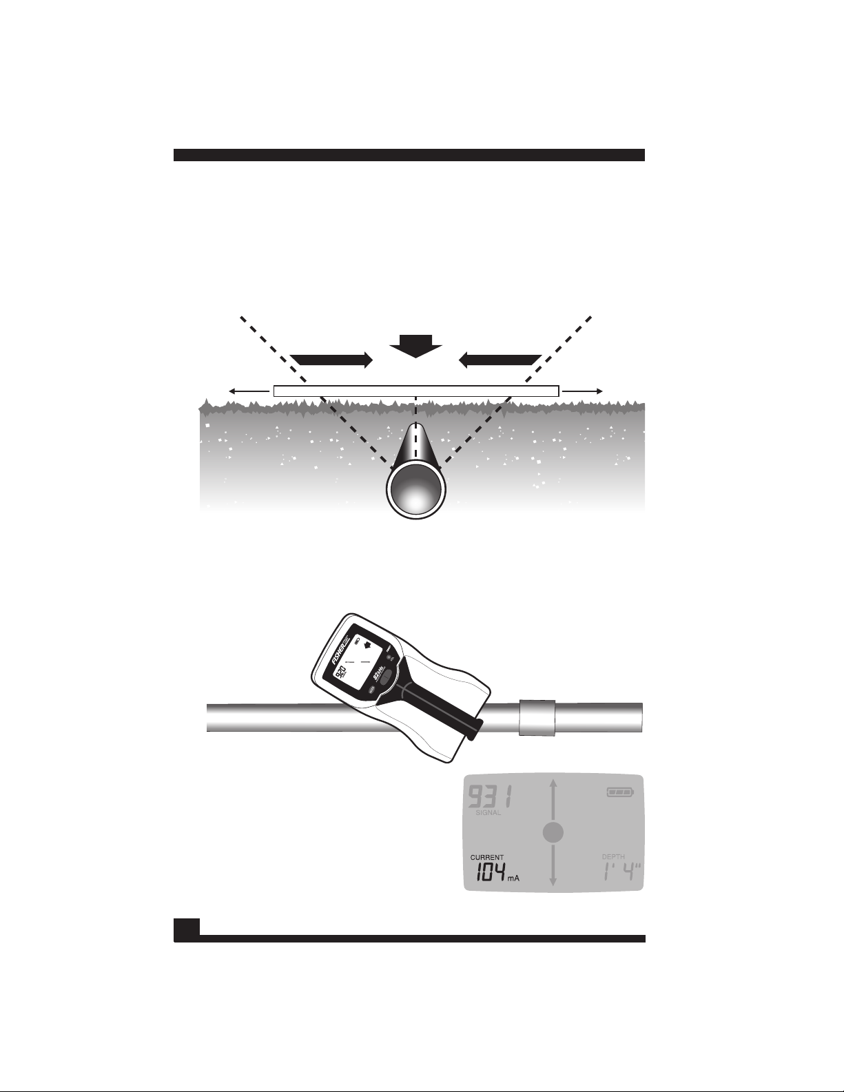
The depth reading is a measure of the distance between the tip
of the Receiver blade and the center of the buried utility. When
the device is directly over a buried utility, as indicated by the
Over-Target indicator, depth will automatically be displayed in
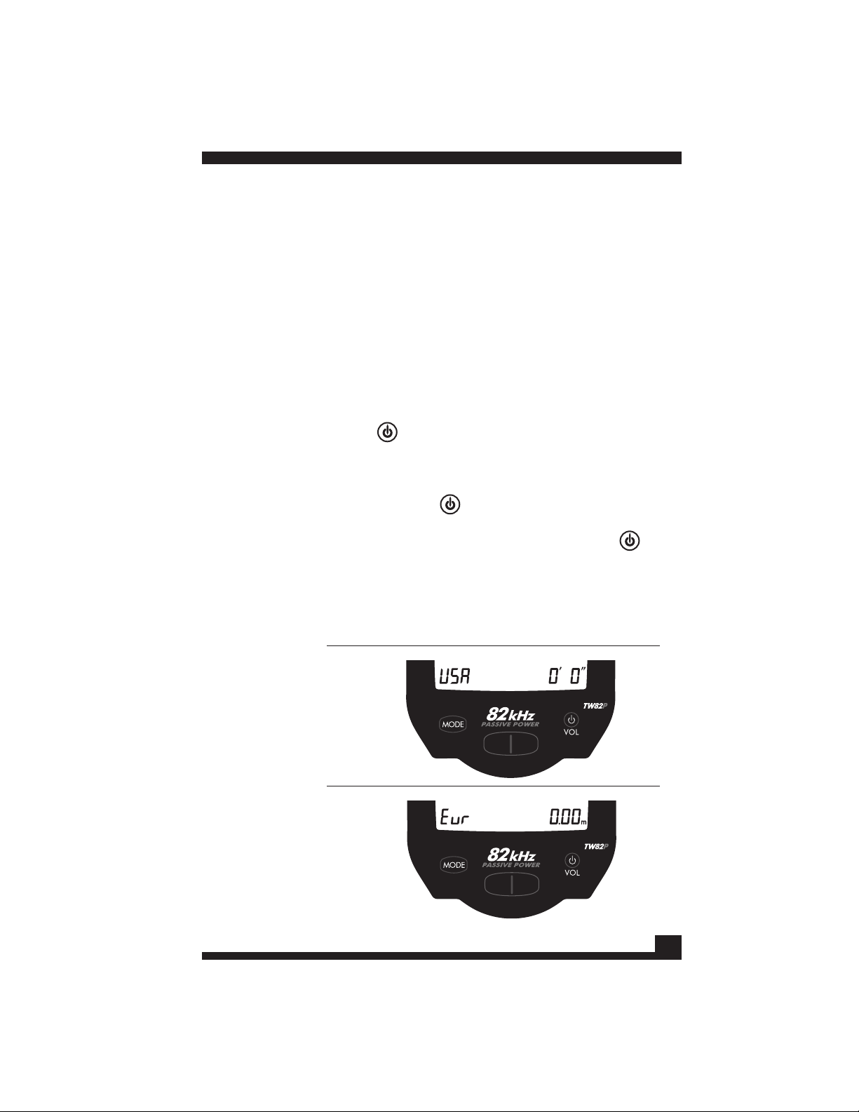
feet and inches (meters if metric).
In general, the accuracy of any
depth measurement will be
inuenced by factors such as
proper azimuth orientation of
the device, eld strength and
the roundness of the eld. The
only 100% reliable method for
determining the depth of any
buried utility is to hand-excavate.
6. Battery Strength: When battery life declines to less than one hour
of operation, the battery indicator outline will be illuminated
with no segments. When the
batteries reach the end of their
useful life, the screen will go
blank and the battery icon will
ash before the Receiver shuts
off. Expect about 100 hours of
battery life from a set of high
quality D-cell alkaline batteries.
NOTE. Overhead Power Line
Interference: When the Receiver encounters an interfering
overhead electrical eld stronger than the eld from an energized
buried line, the Receiver will display zeros, “000”, for the Depth
and Current measurements.
In this case, the eld from the overhead power line is interfering
with the signal from the buried line you are trying to trace. You
may still be able to trace the buried line, but the accuracy of your
trace will be impaired by this interference.
STANDARD MODE continued
current
depth
www.GlobalTestSupply.com
Find Quality Products Online at: sales@GlobalTestSupply.com

12
At some sites, utility lines branching off from a main line may be
difcult to trace using the Standard Mode. In
these circumstances, use the Lateral Mode.
At such sites, the signal from a main
line is so strong that it overwhelms
the single from a lateral line. In
this illustration, gas service
lines connecting to homes
from a main gas line may
carry far less current than
the main line. This weaker
current could be the result
of a lateral line that is
shorter than the main line,
or a lateral that is not well
grounded.
LATERAL MODE
TW-82P RECEIVER
When conducting a trace of the Lateral line, select LATERAL Mode
and walk parallel to the main line (as in the illustration below). You
must use Lateral Mode in this situation because in the Regular Mode,
you may detect the signal from the main line all of the way up to the
house, even with the blade of the Receiver parallel to the main line.
The Lateral Mode is
congured to ignore the
signal coming from the
parallel main line and
detect signals coming
from the perpendicular
lateral lines. The Lateral
Mode may still detect
the main line in very
close proximity, even
though the Receiver
blade is parallel to it. So
maintain a minimum
distance of 6 to 12 feet
from the main line when
tracing lateral lines.
Walk parallel to the
main line, holding the
blade of the Receiver
perpendicular to the
lateral lines.
LATERAL LINE
LATERAL LINE
WALK PARALLEL TO MAIN LINE
Blade is
perpendicular
to lateral line
www.GlobalTestSupply.com
Find Quality Products Online at: sales@GlobalTestSupply.com

13
LATERAL MODE continued
TW-82P RECEIVER
Press to enter Lateral Mode.
will appear on the LCD display.
LATERAL TRACING OPERATION
While tracing a line using the Lateral Mode, the display will appear as
illustrated below. The SIGNAL number indicates the strength of the
eld emitted by the buried line. The buried line is located at the spot
where the maximum SIGNAL number
is indicated. If you move left or right
of the spot where the maximum
SIGNAL number is found, the value
displayed will fall.
Walk across the location of
the lateral line with the blade
perpendicular to the lateral line.
Programming:
While in Lateral Mode, press-and-hold to program:
• To exit Lateral programming, press-and-hold again.
• To set the upper limit of the signal range, press .
Each press of toggles through the program choices:
50, 100, 150, 200, 250 or 300
Set this upper limit just above the maximum SIGNAL strength
number that appears during your lateral trace.
The correct setting will make it easier to hear the peak in the
signal as you pass over the lateral line.
Set the number just above the highest SIGNAL number.
Examples:
If the highest lateral
SIGNAL number is: Set to:
137 150
159 200
310 300 (300 is the maximum possible)
Changes to this upper limit of the
SIGNAL RANGE are saved to memory.
Changing this upper limit is similar
to the gain adjustment on other line
tracers which use a peak mode of
operation. Set the number just above
the highest SIGNAL number, as
described above.
www.GlobalTestSupply.com
Find Quality Products Online at: sales@GlobalTestSupply.com

14
TW-82P RECEIVER
PASSIVE POWER MODE
While the Standard and Lateral Modes use the 82kHz signal injected
by the Transmitter, in some cases it is desirable to locate buried
utilities by tracing electric power currents running through them.
Buried utilities may be energized by the electric power currents
running directly through them, current coupling into them as a result
of leakage from power cable faults, defective electrical loads that leak
AC power into ground connections or from cathodic protection on
metal pipelines.
The Passive Power Mode detects both 50Hz and 60Hz electric currents
as well as harmonics of these frequencies resulting from distortions
caused by electrical loads being served by the utility. Cathodic
Protection (at 100Hz or 120Hz) is also detected. This mode will usually,
but not always, detect underground AC power lines. It does not detect
voltage and will usually not detect a power line which is not delivering
current, i.e. one that is not under a load. The operator must use his
knowledge of infrastructure and each specic area being located to
interpret the character of each underground utility.
ABSENCE OF A DETECTABLE POWER SIGNAL DOES NOT
GUARANTEE THAT NO POWER IS PRESENT.
Among the important uses of the Passive Power Mode is to check
ground connections being considered for use as a transmitter
connection to do a conductive trace. Many “grounds” are in fact
improperly grounded and/or have substantial AC power
flowing through them due to defective installation or defective
loads. Ground connections should always be treated as though they
have dangerous voltage or current on them. If the Passive Power
Mode detects power current owing in a proposed ground connection,
it is usually advisable to use some other ground connection if
available. REMINDER: This mode does not detect voltage. A oating
ground with power voltage on it will probably not be detected. A
high-impedance AC voltmeter can be used to detect voltage provided
that another ground is available to measure the voltage differential.
Floating grounds with full line voltage on them can usually be detected
with a neon bulb line tester without the need for a second ground
connection; follow the instructions provided by the manufacturer.
www.GlobalTestSupply.com
Find Quality Products Online at: sales@GlobalTestSupply.com

15
TW-82P RECEIVER
PASSIVE POWER MODE continued
Operating Controls
Press to enter Passive Power Mode
The display will appear as
illustrated to the right.
Press to increase gain.
Press to decrease gain.
Press again to exit Passive Power Mode.
Locating Procedure
1. Enter Passive Power mode.
2. Set gain at maximum, 100%.
3. If necessary, reduce the gain so that the Receiver is silent when
not over a detectable power line.
4. Walk forward, swinging the Receiver from side to side.
5. When a line is located, the Receiver will emit a raspy/buzzing
sound.
Note: Audible-search only. No visual indicators.
Passive Power detection relies only on audio feedback to locate
the utility. No indicators will appear on the LCD display.
Azimuth, depth and left/right guidance will not be provided.
6. When an audible signal indicates the detection of a utility:
a. Move left and right, sweeping beyond the range of the signal
each time as you sweep the Receiver.
b. Determine the approximate center of the signal, midway
between the right-most and left-most edges of the audible
signal.
c. Lower the gain as you sweep left and right of the approximate
center. This will narrow the search.
d. Continue to lower the gain to the minimum possible while still
detecting the buried utility with an audible alert.
7. With the utility pinpointed at one spot, move both forward and
backward to verify the direction of the utility.
8. If possible, follow the signal to a known access point, or origin, to
nd a connection point visible above ground.
9. If appropriate, use inductive or conductive modes to locate the
utility and verify the location of the utility.
www.GlobalTestSupply.com
Find Quality Products Online at: sales@GlobalTestSupply.com

16
TW-82P RECEIVER
PASSIVE POWER MODE continued
SEARCH
IN A GRID
WALK WITH BLADE
PERPENDICULAR
TO THE UTILITY
UTILITY WILL NOT
BE DETECTED WHEN
THE RECEIVER
BLADE PASSES PARALLEL
Grid Search: To ensure complete coverage of the area, map out a grid of
intersecting lines covering the search area. Walk the grid at intersecting
right-angles. Power lines will be detected when the blade of the Receiver
is perpendicular to the utility. You will not detect the line when crossing
over parallel to a utility.
www.GlobalTestSupply.com
Find Quality Products Online at: sales@GlobalTestSupply.com

17
Display during Programming
IMPERIAL
METRIC
AUTO POWER-DOWN, RECEIVER
When 90 minutes have passed without the operator pressing
any control buttons, the Receiver will automatically power
down.
• Lower left of the display will indicate “OFF”.
• Lower right of the display will count down from 10 to 0.
• The Receiver will then turn off.
To stop Auto Power-Down, press any button once.
METRIC / IMPERIAL UNIT OF MEASURE
To change the Receiver unit of measure, follow this procedure:
1. Start with the Receiver OFF.
2. Press-and-Hold for 6 seconds.
a. The Receiver will turn on in Standard mode.
b. After 6 seconds, the new unit of measure will indicate at the
bottom of the display.
c. If you continue to hold , the alternate unit of measure
will be displayed.
d. When you see the desired unit of measure, release . The
Receiver will commence operation using the last displayed
unit of measure.
TW-82P RECEIVER
www.GlobalTestSupply.com
Find Quality Products Online at: sales@GlobalTestSupply.com

SPECIFICATIONS
RECEIVER
Frequency .....................................82.175 kHz
Standard Mode.............................Automatic response
Lateral Mode ................................Programmable
Left/Right Guidance.....................Audible and visual
Azimuth Indicator........................Visual
Over-Target Indicator .................. Visual and audible
Battery Status..............................Visual
Signal Strength Indicator............Numeric display & audible
Signal Current Measurement .....Numeric display, automatic
Depth Measurement ....................Numeric display, automatic
Battery Type................................. Two D-cell batteries (included)
Battery Life .................................. From 80 to 130 hours, depending
................................................on the volume setting
Weight, with batteries..................3.60 lbs
Passive Power...............................50Hz and 60Hz detection.
................................................Cathodic Protection detection.
www.GlobalTestSupply.com
Find Quality Products Online at: sales@GlobalTestSupply.com
Table of contents
Popular Receiver manuals by other brands

Televes
Televes RSD - 7296 user manual

Motorola
Motorola DCP501 - DVD Player / AV Receiver Troubleshooting

Marantz
Marantz NR1604 Getting started guide

CaryMart
CaryMart S12CA-DC09-ANT2 manual

Panasonic
Panasonic SAHE9 - RECEIVER operating instructions

Coopers of Stortford
Coopers of Stortford 10708 Instructions for use