Ublox NEO-M9N Use and care manual

NEO-M9N
Standard precision GNSS module
Integration manual
Abstract
Integration manual describing the u-blox NEO-M9N GNSS module. NEO-
M9N offers ultra-robust meter-level GNSS positioning performance with
concurrent reception of up to four GNSS (GPS, GLONASS, BeiDou, Galileo)
in a 12.2 x 16.0 mm package.
www.u-blox.com
UBX-19014286 - R07
C1-Public

NEO-M9N-Integration manual
Document information
Title NEO-M9N
Subtitle Standard precision GNSS module
Document type Integration manual
Document number UBX-19014286
Revision and date R07 13-Dec-2021
Disclosure restriction C1-Public
This document applies to the following products:
Type number Firmware version IN/PCN reference RN reference
NEO-M9N-00B-00 SPG 4.04 UBX-21029274 UBX-20036165
u-blox or third parties may hold intellectual property rights in the products, names, logos and designs included in this
document. Copying, reproduction, modification or disclosure to third parties of this document or any part thereof is only
permitted with the express written permission of u-blox.
The information contained herein is provided "as is" and u-blox assumes no liability for its use. No warranty, either express
or implied, is given, including but not limited to, with respect to the accuracy, correctness, reliability and fitness for a
particular purpose of the information. This document may be revised by u-blox at any time without notice. For the most recent
documents, visit www.u-blox.com.
Copyright © 2021, u-blox AG.
UBX-19014286 - R07
Page 2 of 95
C1-Public

NEO-M9N-Integration manual
Contents
1 Integration manual overview............................................................................................. 6
2 System description...............................................................................................................7
2.1 Overview.................................................................................................................................................... 7
2.2 Architecture..............................................................................................................................................7
2.2.1 Block diagram..................................................................................................................................7
3 Receiver functionality.......................................................................................................... 8
3.1 Receiver configuration........................................................................................................................... 8
3.1.1 Changing the receiver configuration..........................................................................................8
3.1.2 Default GNSS configuration.........................................................................................................8
3.1.3 Default interface settings............................................................................................................ 9
3.1.4 Basic receiver configuration.........................................................................................................9
3.1.5 RTCM corrections........................................................................................................................ 10
3.1.6 Legacy configuration interface compatibility........................................................................ 11
3.1.7 Navigation configuration............................................................................................................11
3.2 SBAS........................................................................................................................................................16
3.3 Geofencing..............................................................................................................................................17
3.3.1 Introduction................................................................................................................................... 17
3.3.2 Interface......................................................................................................................................... 17
3.3.3 Geofence state evaluation......................................................................................................... 18
3.3.4 Using a PIO for geofence state output................................................................................... 18
3.4 Logging....................................................................................................................................................18
3.4.1 Introduction................................................................................................................................... 18
3.4.2 Setting the logging system up................................................................................................. 19
3.4.3 Information about the log.......................................................................................................... 19
3.4.4 Recording....................................................................................................................................... 20
3.4.5 Retrieval......................................................................................................................................... 21
3.4.6 Command message acknowledgment....................................................................................22
3.5 Data batching........................................................................................................................................22
3.5.1 Introduction................................................................................................................................... 22
3.5.2 Setting up the data batching....................................................................................................22
3.5.3 Retrieval......................................................................................................................................... 23
3.6 Spectrum analyzer............................................................................................................................... 23
3.7 Communication interfaces................................................................................................................. 24
3.7.1 UART...............................................................................................................................................25
3.7.2 I2C interface..................................................................................................................................26
3.7.3 SPI interface..................................................................................................................................29
3.7.4 USB interface................................................................................................................................30
3.8 Predefined PIOs.....................................................................................................................................31
3.8.1 D_SEL..............................................................................................................................................31
3.8.2 RESET_N........................................................................................................................................ 31
3.8.3 SAFEBOOT_N................................................................................................................................31
3.8.4 TIMEPULSE................................................................................................................................... 32
3.8.5 TX_READY..................................................................................................................................... 32
3.8.6 EXTINT............................................................................................................................................32
UBX-19014286 - R07
Contents Page 3 of 95
C1-Public

NEO-M9N-Integration manual
3.9 Multiple GNSS assistance (MGA)..................................................................................................... 33
3.9.1 Authorization................................................................................................................................ 33
3.9.2 Preserving MGA and operational data during power-off..................................................... 33
3.9.3 AssistNow Offline........................................................................................................................ 34
3.9.4 AssistNow Autonomous.............................................................................................................37
3.10 Save-on-shutdown feature...............................................................................................................41
3.11 Power management...........................................................................................................................42
3.11.1 Continuous mode.......................................................................................................................43
3.11.2 Power save mode.......................................................................................................................43
3.11.3 Peak current settings............................................................................................................... 50
3.11.4 Power on/off command............................................................................................................ 51
3.11.5 EXTINT pin control when power save mode is not active................................................. 51
3.11.6 Measurement and navigation rate with power save mode...............................................51
3.11.7 Backup modes............................................................................................................................51
3.12 Clocks and time.................................................................................................................................. 52
3.12.1 Receiver local time.................................................................................................................... 52
3.12.2 Navigation epochs..................................................................................................................... 52
3.12.3 iTOW timestamps..................................................................................................................... 53
3.12.4 GNSS times.................................................................................................................................53
3.12.5 Time validity................................................................................................................................53
3.12.6 UTC representation...................................................................................................................54
3.12.7 Leap seconds..............................................................................................................................55
3.12.8 Real-time clock...........................................................................................................................55
3.12.9 Date...............................................................................................................................................55
3.13 Timing functionality...........................................................................................................................56
3.13.1 Time pulse...................................................................................................................................56
3.13.2 Timemark.................................................................................................................................... 60
3.14 Security.................................................................................................................................................61
3.14.1 Spoofing detection / monitoring............................................................................................ 61
3.14.2 Jamming/interference detection / monitoring....................................................................62
3.14.3 GNSS receiver integrity............................................................................................................63
3.15 u-blox protocol feature descriptions.............................................................................................. 63
3.15.1 Broadcast navigation data...................................................................................................... 63
3.16 Forcing a receiver reset.....................................................................................................................67
3.17 Firmware upload................................................................................................................................. 68
4 Design..................................................................................................................................... 69
4.1 Pin assignment......................................................................................................................................69
4.2 Power supply.......................................................................................................................................... 70
4.2.1 VCC: Main supply voltage.......................................................................................................... 70
4.2.2 V_BCKP: Backup supply voltage............................................................................................... 70
4.2.3 V_USB: USB interface power supply........................................................................................ 71
4.3 NEO-M9N minimal design.................................................................................................................. 71
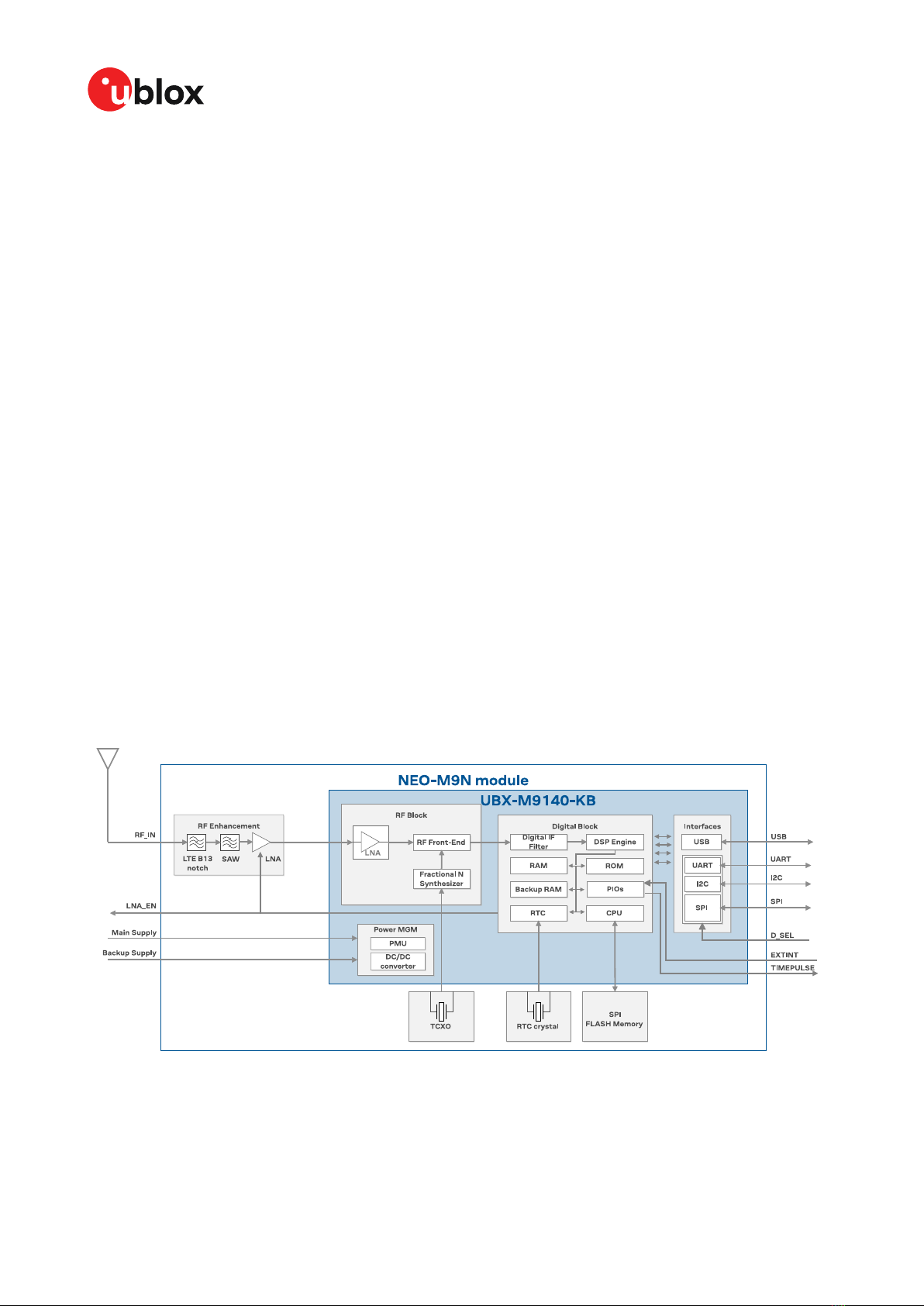
4.4 NEO-M9N internal components........................................................................................................ 72
4.4.1 Clock generation...........................................................................................................................72
4.4.2 Real-time clock (RTC)..................................................................................................................72
4.4.3 SAW and LNA............................................................................................................................... 72
4.4.4 VCC_RF antenna bias voltage...................................................................................................72
4.4.5 Flash memory............................................................................................................................... 72
4.5 Antenna...................................................................................................................................................72
4.5.1 Antenna design with passive antenna....................................................................................73
UBX-19014286 - R07
Contents Page 4 of 95
C1-Public

NEO-M9N-Integration manual
4.5.2 Antenna design with external LNA or active antenna......................................................... 73
4.5.3 Out-of-band blocking immunity................................................................................................75
4.6 EOS/ESD precautions.......................................................................................................................... 75
4.6.1 ESD protection measures.......................................................................................................... 76
4.6.2 EOS precautions...........................................................................................................................76
4.6.3 Safety precautions...................................................................................................................... 77
4.7 Electromagnetic interference on I/O lines.......................................................................................77
4.7.1 General notes on interference issues......................................................................................77
4.7.2 In-band interference mitigation................................................................................................78
4.7.3 Out-of-band interference........................................................................................................... 78
4.8 Layout......................................................................................................................................................79
4.8.1 Placement...................................................................................................................................... 79
4.8.2 Thermal management................................................................................................................ 79
4.8.3 Package footprint, copper and paste mask........................................................................... 79
4.8.4 Layout guidance........................................................................................................................... 81
4.9 Design guidance....................................................................................................................................82
4.9.1 General considerations............................................................................................................... 82
4.9.2 Backup battery............................................................................................................................. 83
4.9.3 RF front-end circuit options...................................................................................................... 83
4.9.4 Antenna/RF input........................................................................................................................ 84
4.9.5 Ground pads.................................................................................................................................. 84
4.9.6 Schematic design........................................................................................................................ 84
4.9.7 Layout design-in guideline......................................................................................................... 84
5 Product handling................................................................................................................. 85
5.1 ESD handling precautions.................................................................................................................. 85
5.2 Soldering.................................................................................................................................................85
5.3 Packaging............................................................................................................................................... 88
5.4 Tapes....................................................................................................................................................... 88
5.5 Reels........................................................................................................................................................ 89
5.6 Moisture sensitivity levels.................................................................................................................. 89
Appendix.................................................................................................................................... 90
A Migration....................................................................................................................................................90
B Glossary......................................................................................................................................................92
Related documents................................................................................................................ 93
Revision history.......................................................................................................................94
UBX-19014286 - R07
Contents Page 5 of 95
C1-Public

NEO-M9N-Integration manual
1 Integration manual overview
This document is an important source of information on all aspects of NEO-M9N system, software
and hardware design. The purpose of this document is to provide guidelines for a successful
integration of the receiver with the customer's end product.
UBX-19014286 - R07
1 Integration manual overview Page 6 of 95
C1-Public

NEO-M9N-Integration manual
2 System description
2.1 Overview
The NEO-M9N GNSS receiver features the u-blox M9 standard precision GNSS platform , and
provides exceptional sensitivity and acquisition times for all L1 GNSS systems. u-blox M9 receivers
are available in different variants to serve automotive and industrial tracking applications, such as
navigation, telematics and UAVs.
The u-blox M9 standard precision GNSS platform, which delivers meter-level accuracy, succeeds the
well-known u-blox M8 product range.
u-blox M9 receivers support concurrent reception of four GNSS. The high number of visible satellites
allows the receiver to select the best signals. This maximizes the position accuracy, in particular
under challenging conditions such as deep urban canyons.
u-blox M9 receivers detect jamming and spoofing events and report them to the host, which allows
the system to react to such events. Advanced filtering algorithms mitigate the impact of RF
interference and jamming, thus enabling the product to operate as intended.
The receiver also provides higher navigation rate and improved security features compared to
previous u-blox GNSS generations.
The NEO-M9N module is available in the 12.2 x 16.0 mm NEO form factor LCC package.
2.2 Architecture
The NEO-M9N receiver provides all the necessary RF and baseband processing to enable multi-
constellation operation. The block diagram below shows the key functionality.
2.2.1 Block diagram
Figure 1: NEO-M9N block diagram
UBX-19014286 - R07
2 System description Page 7 of 95
C1-Public

NEO-M9N-Integration manual
3 Receiver functionality
This section describes the NEO-M9N operational features and their configuration.
3.1 Receiver configuration
The NEO-M9N is fully configurable with UBX configuration interface keys. The configuration
database in the receiver's RAM holds the current configuration, which is used by the receiver
at run-time. It is constructed on start-up of the receiver from several sources of configuration.
The configuration interface and the available keys are described fully in the applicable interface
description [2].
A configuration setting stored in RAM remains effective until power-down or reset. If stored in
BBR (battery-backed RAM), the setting will be used as long as the backup battery supply remains.
Configuration settings can be saved permanently in flash memory.
CAUTION The configuration interface has changed from earlier u-blox positioning receivers.
Legacy messages are deprecated, and will not be supported in future firmware releases.
Users are advised to adopt the configuration interface described in this document. See
legacy UBX-CFG message fields reference section in the applicable interface description [2].
Configuration interface settings are held in a database consisting of separate configuration items.
An item is made up of a pair consisting of a key ID and a value. Related items are grouped together
and identified under a common group name: CFG-GROUP-*; a convention used in u-center and
within this document. Within u-center, a configuration group is identified as "Group name" and the
configuration item is identified as the "item name" under the "Generation 9 Configuration View" -
"Advanced Configuration" view.
The UBX messages available to change or poll the configurations are the UBX-CFG-VALSET, UBX-
CFG-VALGET, and UBX-CFG-VALDEL messages. For more information about these messages and
the configuration keys see the configuration interface section in the applicable interface description
[2].
3.1.1 Changing the receiver configuration
All configuration messages, including legacy UBX-CFG messages, will result in a UBX-ACK-ACK
or UBX-ACK-NAK response. If several configuration messages are sent without waiting for this
response then the receiver may pause processing of input messages until processing of a previous
configuration message has been completed. When this happens a warning message "wait for cfg
ACK" will be sent to the host.
3.1.2 Default GNSS configuration
The NEO-M9N default GNSS configuration is set as follows:
• GPS: L1C/A
• GLONASS: L1OF
• Galileo: E1B/C
• BeiDou: B1I
• QZSS: L1C/A
• SBAS: L1C/A
UBX-19014286 - R07
3 Receiver functionality Page 8 of 95
C1-Public

NEO-M9N-Integration manual
For more information about the default configuration, see the applicable interface description [2].
3.1.3 Default interface settings
Interface Settings
UART 38400 baud, 8 bits, no parity bit, 1 stop bit.
Output messages: NMEA GGA, GLL, GSA, GSV, RMC, VTG, TXT (no UBX).
Input protocols: UBX, NMEA and RTCM 3.3.
USB Output messages activated as in UART. Input protocols available as in UART.
I2C Output messages activated as in UART. Input protocols available as in UART.
SPI Output messages activated as in UART. Input protocols available as in UART.
Table 1: Default interface settings
Refer to the applicable interface description [2] for information about further settings.
By default the NEO-M9N outputs NMEA messages that include satellite data for all GNSS bands
being received. This results in a higher-than-before NMEA load output for each navigation period.
Make sure the UART baud rate being used is sufficient for the selected navigation rate and the
number of GNSS signals being received.
3.1.4 Basic receiver configuration
This section summarizes the basic receiver configuration most commonly used.
3.1.4.1 Basic hardware configuration
The NEO-M9N receiver has been configured with default setting already during the module
production. The receiver starts up and is fully operational as soon as proper power supply,
communication interfaces and antenna signal from the application have been connected.
3.1.4.2 Communication interface configuration
Several configuration groups allow operation mode configuration of the various communication
interfaces. These include parameters for the data framing, transfer rate and enabled input/output
protocols. See Communication interfaces section for details. The configuration groups available for
each interface are:
Interface Configuration groups
UART1 CFG-UART1-*, CFG-UART1INPROT-*, CFG-UART1OUTPROT-*
USB CFG-USB-*, CFG-USBINPROT-*, CFG-USBOUTPROT-*
I2C CFG-I2C-*, CFG-I2CINPROT-*, CFG-I2COUTPROT-*
SPI CFG-SPI-*, CFG-SPIINPROT-*, CFG-SPIOUTPROT-*
Table 2: Interface configurations
3.1.4.3 Message output configuration
This product supports two protocols for output messages. One is NMEA and the other one is a u-
blox proprietary "UBX" protocol. NMEA is a well-known industry standard, used mainly for providing
information about position, time and satellites. UBX messages can be used to configure the receiver
and also to periodically provide information about position, time and satellites. With the UBX
protocol it is easy to monitor the receiver status and get much deeper information about the receiver
status. The rate of NMEA and UBX protocol output messages are configurable and it is possible to
enable or disable single NMEA or UBX messages individually.
If the rate configuration value is zero, then the corresponding message will not be output. Values
greater than zero indicate how often the message is output.
UBX-19014286 - R07
3 Receiver functionality Page 9 of 95
C1-Public

NEO-M9N-Integration manual
For periodic output messages the rate relates to the event the message is related to. For example,
the UBX-NAV-PVT (navigation, position, velocity and time solution) is related to the navigation
epoch. If the rate of this message is set to one (1), it will be output for every navigation epoch. If the
rate is set to two (2), it will be output every other navigation epoch. The rates of the output messages
are individually configurable per communication interface. See the CFG-MSGOUT-* configuration
group.
Some messages, such as UBX-MON-VER, are non-periodic and will only be output as an answer to
a poll request.
The UBX-INF-* and NMEA-Standard-TXT information messages are non-periodic output messages
that do not have a message rate configuration. Instead they can be enabled for each communication
interface via the CFG-INFMSG-* configuration group.
All message output is additionally subject to the protocol configuration of the
communication interfaces. Messages of a given protocol will not be output until the protocol
is enabled for output on the interface (see Communication interface configuration).
3.1.4.4 GNSS signal configuration
The GNSS constellations are configurable with configuration keys. Each GNSS constellation can be
enabled or disabled independently.
3.1.5 RTCM corrections
RTCM is a binary data protocol for communication of GNSS correction information. The NEO-
M9N module supports RTCM as specified by RTCM 10403.3, Differential GNSS (Global Navigation
Satellite Systems) Services – Version 3 (October 7, 2016).
The RTCM specification is currently at version 3.3 and RTCM version 2 messages are not supported
by this standard.
To modify the RTCM input/output settings, see the configuration section in the applicable interface
description [2].
3.1.5.1 NTRIP - networked transport of RTCM via internet protocol
Networked Transport of RTCM via internet protocol, or NTRIP, is an open standard protocol for
streaming differential data and other kinds of GNSS streaming data over the internet in accordance
with specifications published by RTCM.
There are three major parts to the NTRIP system: The NTRIP client, the NTRIP server, and the NTRIP
caster:
1. The NTRIP server is a PC or an on-board computer running NTRIP server software
communicating directly with a GNSS reference station. The NTRIP server serves as the
intermediary between the GNSS receiver (NTRIP Source) streaming correction data and the
NTRIP caster.
2. The NTRIP caster is an HTTP server which receives streaming correction data from one or
more NTRIP servers and in turn streams the correction data to one or more NTRIP clients via
the internet.
3. The NTRIP client receives streaming correction data from the NTRIP caster to apply as real-
time corrections to a GNSS receiver.
u-center GNSS evaluation software provides an NTRIP client application that can help to evaluate a
NEO-M9N design. The u-center NTRIP client connects over the internet to an NTRIP service provider,
using access credentials such as user name and password from the service provider. The u-center
NTRIP client then forwards the RTCM 3.3 corrections to a NEO-M9N receiver connected to the local
UBX-19014286 - R07
3 Receiver functionality Page 10 of 95
C1-Public

NEO-M9N-Integration manual
u-center application. RTCM corrections from a virtual reference service are also supported by the u-
center NTRIP client.
3.1.6 Legacy configuration interface compatibility
Although there is some backwards compatibility for the legacy UBX-CFG configuration messages,
users are strongly advised to adopt the configuration interface described in this document.
See Legacy UBX-CFG message fields reference section in the applicable interface description [2].
3.1.7 Navigation configuration
This section presents various configuration options related to the navigation engine. These options
can be configured through CFG-NAVSPG-* configuration keys.
3.1.7.1 Platform settings
u-blox receivers support different dynamic platform models (see the table below) to adjust the
navigation engine to the expected application environment. These platform settings can be
changed dynamically without performing a power cycle or reset. The settings improve the receiver's
interpretation of the measurements and thus provide a more accurate position output. Setting the
receiver to an unsuitable platform model for the given application environment is likely to result in
a loss of receiver performance and position accuracy.
The dynamic platform model can be configured through the CFG-NAVSPG-DYNMODEL
configuration item. The supported dynamic platform models and their details can be seen in Table
3 and Table 4 below.
Platform Description
Portable (default) Applications with low acceleration, e.g. portable devices. Suitable for most situations.
Stationary Used in timing applications (antenna must be stationary) or other stationary applications.
Velocity restricted to 0 m/s. Zero dynamics assumed.
Pedestrian Applications with low acceleration and speed, e.g. how a pedestrian would move. Low
acceleration assumed.
Automotive Used for applications with equivalent dynamics to those of a passenger car. Low vertical
acceleration assumed.
At sea Recommended for applications at sea, with zero vertical velocity. Zero vertical velocity assumed.
Sea level assumed.
Airborne <1g Used for applications with a higher dynamic range and greater vertical acceleration than a
passenger car. No 2D position fixes supported.
Airborne <2g Recommended for typical airborne environments. No 2D position fixes supported.
Airborne <4g Only recommended for extremely dynamic environments. No 2D position fixes supported.
Wrist Only recommended for wrist-worn applications. Receiver will filter out arm motion.
Table 3: Dynamic platform models
Platform Max altitude [m] Max horizontal
velocity [m/s]
Max vertical velocity
[m/s]
Sanity check type Max
position
deviation
Portable 12000 310 50 Altitude and velocity Medium
Stationary 9000 10 6 Altitude and velocity Small
Pedestrian 9000 30 20 Altitude and velocity Small
Automotive 6000 100 15 Altitude and velocity Medium
At sea 500 25 5 Altitude and velocity Medium
Airborne <1g 80000 100 6400 Altitude Large
UBX-19014286 - R07
3 Receiver functionality Page 11 of 95
C1-Public

NEO-M9N-Integration manual
Platform Max altitude [m] Max horizontal
velocity [m/s]
Max vertical velocity
[m/s]
Sanity check type Max
position
deviation
Airborne <2g 80000 250 10000 Altitude Large
Airborne <4g 80000 500 20000 Altitude Large
Wrist 9000 30 20 Altitude and velocity Medium
Table 4: Dynamic platform model details
Applying dynamic platform models designed for high acceleration systems (e.g. airborne <2g) can
result in a higher standard deviation in the reported position.
If a sanity check against a limit of the dynamic platform model fails, then the position solution
is invalidated. Table 4 above shows the types of sanity checks which are applied for a particular
dynamic platform model.
3.1.7.2 Navigation input filters
The navigation input filters in CFG-NAVSPG-* configuration group provide the input data of the
navigation engine.
Configuration item Description
CFG-NAVSPG-FIXMODE By default, the receiver calculates a 3D position fix if possible but reverts to 2D
position if necessary (auto 2D/3D). The receiver can be forced to only calculate 2D
(2D only) or 3D (3D only) positions.
CFG-NAVSPG-CONSTR_ALT, CFG-
NAVSPG-CONSTR_ALTVAR
The fixed altitude is used if fixMode is set to 2D only. A variance greater than zero
must also be supplied.
CFG-NAVSPG-INFIL_MINELEV Minimum elevation of a satellite above the horizon in order to be used in the
navigation solution. Low elevation satellites may provide degraded accuracy, due to
the long signal path through the atmosphere.
CFG-NAVSPG-INFIL_NCNOTHRS,
CFG-NAVSPG-INFIL_CNOTHRS
A navigation solution will only be attempted if there are at least the given number of
SVs with signals at least as strong as the given threshold.
Table 5: Navigation input filter parameters
If the receiver only has three satellites for calculating a position, the navigation algorithm uses a
constant altitude to compensate for the missing fourth satellite. When a satellite is lost after a
successful 3D fix (min four satellites available), the altitude is kept constant at the last known value.
This is called a 2D fix.
u-blox receivers do not calculate any navigation solution with less than three satellites.
3.1.7.3 Navigation output filters
The result of a navigation solution is initially classified by the fix type (as detailed in the fixType
field of UBX-NAV-PVT message). This distinguishes between failures to obtain a fix at all ("No Fix")
and cases where a fix has been achieved, which are further subdivided into specific types of fixes
(e.g. 2D, 3D, dead reckoning).
The NEO-M9N firmware does not support the dead reckoning position fix type.
Where a fix has been achieved, a check is made to determine whether the fix should be classified as
valid or not. A fix is only valid if it passes the navigation output filters as defined in CFG-NAVSPG-
OUTFIL. In particular, both PDOP and accuracy values must be below the respective limits.
Important: Users are recommended to check the gnssFixOK flag in the UBX-NAV-PVT or
the NMEA valid flag. Fixes not marked valid should not be used.
UBX-19014286 - R07
3 Receiver functionality Page 12 of 95
C1-Public

NEO-M9N-Integration manual
UBX-NAV-STATUS message also reports whether a fix is valid in the gpsFixOK flag. These
messages have only been retained for backwards compatibility and users are recommended to use
the UBX-NAV-PVT message.
3.1.7.3.1 Speed (3D) low-pass filter
The CFG-ODO-OUTLPVEL configuration item offers the possibility to activate a speed (3D) low-pass
filter. The output of the speed low-pass filter is published in the UBX-NAV-VELNED message (speed
field). The filtering level can be set via the CFG-ODO-VELLPGAIN configuration item and must be
comprised between 0 (heavy low-pass filtering) and 255 (weak low-pass filtering).
The internal filter gain is computed as a function of speed. Therefore, the level as defined in
the CFG-ODO-VELLPGAIN configuration item defines the nominal filtering level for speeds
below 5 m/s.
3.1.7.3.2 Course over ground low-pass filter
The CFG-ODO-OUTLPCOG configuration item offers the possibility to activate a course over ground
low-pass filter when the speed is below 8 m/s. The output of the course over ground (also named
heading of motion 2D) low-pass filter is published in the UBX-NAV-PVT message (headMot field),
UBX-NAV-VELNED message (heading field), NMEA-RMC message (cog field) and NMEA-VTG
message (cogt field). The filtering level can be set via the CFG-ODO-COGLPGAIN configuration item
and must be comprised between 0 (heavy low-pass filtering) and 255 (weak low-pass filtering).
The filtering level as defined in the CFG-ODO-COGLPGAIN configuration item defines the
filter gain for speeds below 8 m/s. If the speed is higher than 8 m/s, no course over ground
low-pass filtering is performed.
3.1.7.3.3 Low-speed course over ground filter
The CFG-ODO-USE_COG activates this feature and the CFG-ODO-COGMAXSPEED, CFG-ODO-
COGMAXPOSACC configuration items offer the possibility to configure a low-speed course over
ground filter (also named heading of motion 2D). This filter derives the course over ground from
position at very low speed. The output of the low-speed course over ground filter is published in the
UBX-NAV-PVT message (headMot field), UBX-NAV-VELNED message (heading field), NMEA-RMC
message (cog field) and NMEA-VTG message (cogt field). If the low-speed course over ground filter
is not configured, then the course over ground is computed as described in section Freezing the
course over ground.
3.1.7.4 Static hold
Static hold mode allows the navigation algorithms to decrease the noise in the position output when
the velocity is below a pre-defined "Static Hold Threshold". This reduces the position wander caused
by environmental factors such as multi-path and improves position accuracy especially in stationary
applications. By default, static hold mode is disabled.
If the speed drops below the defined "Static Hold Threshold", the static hold mode will be activated.
Once static hold mode has been entered, the position output is kept static and the velocity is set to
zero until there is evidence of movement again. Such evidence can be velocity, acceleration, changes
of the valid flag (e.g. position accuracy estimate exceeding the position accuracy mask, see also
section Navigation output filters), position displacement, etc.
The CFG-MOT-GNSSDIST_THRS configuration item additionally allows for configuration of
distance threshold. If the estimated position is farther away from the static hold position than this
threshold, static mode will be quit. The CFG-MOT-GNSSSPEED_THRS configuration item allows you
to set a speed that the static hold will release.
UBX-19014286 - R07
3 Receiver functionality Page 13 of 95
C1-Public

NEO-M9N-Integration manual
Figure 2: Position publication in static hold mode
Figure 3: Flowchart of the static hold mode
UBX-19014286 - R07
3 Receiver functionality Page 14 of 95
C1-Public

NEO-M9N-Integration manual
3.1.7.5 Freezing the course over ground
If the low-speed course over ground filter is deactivated or inactive (see section Low-speed course
over ground filter), the receiver derives the course over ground from the GNSS velocity information.
If the velocity cannot be calculated with sufficient accuracy (e.g., with bad signals) or if the absolute
speed value is very low (under 0.1 m/s) then the course over ground value becomes inaccurate too.
In this case the course over ground value is frozen, i.e. the previous value is kept and its accuracy
is degraded over time. These frozen values will not be output in the NMEA messages NMEA-RMC
and NMEA-VTG unless the NMEA protocol is explicitly configured to do so (see NMEA protocol
configuration in the applicable interface description [2]).
Figure 4: Flowchart of the course over ground freezing
3.1.7.6 Weak signal compensation
In normal operating conditions, low signal strength (i.e. signal attenuation) indicates likely
contamination by multipath. The receiver trusts such signals less in order to preserve the quality of
the position solution in poor signal environments. This feature can result in degraded performance
in situations where the signals are attenuated for another reason, for example due to antenna
placement. In this case, the weak signal compensation feature can be used to restore normal
performance. There are three possible modes:
• Disabled: no weak signal compensation is performed
• Automatic: the receiver automatically estimates and compensates for the weak signal
• Configured: the receiver compensates for the weak signal based on a configured value
These modes can be selected using CFG-NAVSPG-SIGATTCOMP. In the case of the "configured"
mode, the user should input the maximum C/N0 observed in a clear-sky environment, excluding
any outliers or unusually high values. The configured value can have a large impact on the receiver
performance, so it should be chosen carefully.
UBX-19014286 - R07
3 Receiver functionality Page 15 of 95
C1-Public

NEO-M9N-Integration manual
3.2 SBAS
NEO-M9N is capable of receiving multiple SBAS signals concurrently, even from different SBAS
systems (WAAS, EGNOS, MSAS, etc.). They can be tracked and used for navigation simultaneously.
Every SBAS satellite that broadcasts ephemeris or almanac information can be used for navigation,
just like a normal GNSS satellite.
For receiving correction data, the NEO-M9N automatically chooses the best SBAS satellite as its
primary source. It will select only one since the information received from other SBAS satellites is
redundant and could be inconsistent. The selection strategy is determined by the proximity of the
satellites, the services offered by the satellite, the configuration of the receiver (test mode allowed/
disallowed, integrity enabled/disabled) and the signal link quality to the satellite.
If corrections are available from the chosen SBAS satellite and used in the navigation calculation, the
differential status will be indicated in several output messages such as UBX-NAV-PVT, UBX-NAV-
STATUS, UBX-NAV-SAT, NMEA-GGA, NMEA-GLL, NMEA-RMC and NMEA-GNS (see the applicable
interface description [2]). The message UBX-NAV-SBAS provides detailed information about which
corrections are available and applied.
The most important SBAS feature for accuracy improvement is ionosphere correction. The
measured data from regional Ranging and Integrity Monitoring Stations (RIMS) are combined to
make a Total Electron Content (TEC) map. This map is transferred to the receiver via SBAS satellites
to allow a correction of the ionosphere error on each received signal.
Message type Message content Source
0(0/2) Test mode All
1 PRN mask assignment Primary
2, 3, 4, 5 Fast corrections Primary
6 Integrity Primary
7 Fast correction degradation Primary
9 Satellite navigation (ephemeris) All
10 Degradation Primary
12 Time offset Primary
17 Satellite almanac All
18 Ionosphere grid point assignment Primary
24 Mixed fast / long-term corrections Primary
25 Long-term corrections Primary
26 Ionosphere delays Primary
Table 6: Supported SBAS messages
Each satellite services a specific region and its correction signal is only useful within that region.
Planning is crucial to determine the best possible configuration, especially in areas where signals
from different SBAS systems can be received:
•Example 1 - SBAS receiver in North America: In the eastern parts of North America, make sure
that EGNOS satellites do not take preference over WAAS satellites. The satellite signals from
the EGNOS system should be disallowed by using the PRN mask.
•Example 2 - SBAS receiver in Europe: Some WAAS satellite signals can be received in the
western parts of Europe, therefore it is recommended that the satellites from all but the
EGNOS system should be disallowed using the PRN mask.
Although u-blox receivers try to select the best available SBAS correction data, it is
recommended to configure them to exclude unwanted SBAS satellites.
UBX-19014286 - R07
3 Receiver functionality Page 16 of 95
C1-Public

NEO-M9N-Integration manual
To configure the SBAS functionalities use the CFG-SBAS-* configuration group.
Parameter Description
CFG-SIGNAL-SBAS_ENA Enabled/disabled status of the SBAS subsystem
CFG-SBAS-USE_TESTMODE Allow/disallow SBAS usage from satellites in test mode
CFG-SBAS-USE_RANGING Use the SBAS satellites for navigation (ranging)
CFG-SBAS-USE_DIFFCORR Combined enable/disable switch for fast-, long-term and ionosphere corrections
CFG-SBAS-USE_INTEGRITY Apply integrity information data
CFG-SBAS-PRNSCANMASK Allows selectively enabling/disabling SBAS satellites
Table 7: SBAS configuration parameters
When SBAS integrity data are applied, the navigation engine stops using all signals for
which no integrity data are available (including all non-GPS signals). It is not recommended
to enable SBAS integrity on borders of SBAS service regions in order not to inadvertently
restrict the number of available signals.
SBAS integrity information is required for at least 5 GPS satellites. If this condition is not
met, SBAS integrity data will not be applied.
SBAS is only used if no correction services are available. If the connection stream is lost
during the operation, the receiver will switch to using the SBAS corrections after the time
set in CFG-NAVSPG-CONSTR_DGNSSTO (60 s by default) has elapsed.
When the receiver switches from a solution using correction data to a standard position
solution, the reference frame of the output position will switch from the one of the
correction data to that of the standard position solution. For an SBAS solution this
reference frame will be aligned within a few cm of WGS84 (and modern ITRF realizations).
3.3 Geofencing
3.3.1 Introduction
Figure 5: Geofence
The geofencing feature allows for the configuration of up to four circular areas (geofences) on the
Earth's surface. The receiver will then evaluate for each of these areas whether the current position
lies within the area or not and signal the state via UBX messaging and PIO toggling.
3.3.2 Interface
Geofencing can be configured using the CFG-GEOFENCE-* configuration group. The geofence
evaluation is active whenever there is at least one geofence configured.
UBX-19014286 - R07
3 Receiver functionality Page 17 of 95
C1-Public

NEO-M9N-Integration manual
The current state of each geofence plus the combined state is output in UBX-NAV-GEOFENCE with
every navigation epoch.
3.3.3 Geofence state evaluation
With every navigation epoch the receiver will evaluate the current solution's position versus the
configured geofences. There are three possible outcomes for each geofence:
•Inside - The position is inside the geofence with the configured confidence level
•Outside - The position lies outside of the geofence with the configured confidence level
•Unknown - There is no valid position solution or the position uncertainty does not allow for
unambiguous state evaluation
The position solution uncertainty (standard deviation) is multiplied with the configured confidence
sigma level and taken into account when evaluating the geofence state (red circle in Figure 6).
Figure 6: Geofence states
The combined state for all geofences is evaluated as the combination (Union) of all geofences:
•Inside - The position lies inside of at least one geofence
•Outside - The position lies outside of all geofences
•Unknown - All remaining states
3.3.4 Using a PIO for geofence state output
This feature can be used, for example, for waking up a sleeping host when a defined geofence
condition is reached. The receiver will toggle the assigned pin according to the combined geofence
state. Due to hardware restrictions, the geofence unknown state is not configurable and is always
represented as HIGH. If the receiver is in the software backup mode or in the reset state, the pin
will go to HIGH accordingly. The meaning of the LOW state can be configured using the CFG-
GEOFENCE-PINPOL configuration item.
The CFG-GEOFENCE-PIN configuration item refers to a PIO and not a physical device pin.
The PIO number must be set so that it is mapped to the assigned geofence state device pin.
3.4 Logging
3.4.1 Introduction
The logging feature allows position fixes and arbitrary byte strings from the host to be logged in the
receiver's flash memory. Logging of position fixes happens independently of the host system, and
can continue while the host is powered down.
The following table lists all the logging-related messages:
Message Description
UBX-LOG-CREATE Creates a log file and activates the logging system
UBX-LOG-ERASE Erases a log file and deactivates the logging subsystem
UBX-LOG-INFO Provides information about the logging system
UBX-19014286 - R07
3 Receiver functionality Page 18 of 95
C1-Public

NEO-M9N-Integration manual
Message Description
UBX-LOG-STRING Enables a host process to write a string of bytes to the log file
Table 8: Logging control and configuration messages
Message Description
UBX-LOG-RETRIEVE Starts the log retrieval process
UBX-LOG-RETRIEVEPOS A position log entry returned by the receiver
UBX-LOG-RETRIEVEPOSEXTRA Odometer position data
UBX-LOG-RETRIEVESTRING A byte string log entry returned by the receiver
UBX-LOG-FINDTIME Finds the index of the first entry (given time)
Table 9: Logging retrieval messages
3.4.2 Setting the logging system up
An empty log can be created using the UBX-LOG-CREATE message and a log can be deleted with the
UBX-LOG-ERASE message. The logging system will only run if a log is in existence, so most logging
messages will be rejected with a UBX-ACK-NAK message if there is no log present. Only one log
can be created at any one time so a UBX-ACK-NAK message will be returned if a log already exists.
The message specifies the maximum size of the log in bytes (with some pre-set values provided).
Both the logging subsystem and the receiver file-store have implementation overheads, so the total
space available for log entries will be somewhat smaller than the size specified.
UBX-LOG-CREATE also allows the log to be specified as a circular log. If the log is circular, a set of
older log entries will be deleted when it fills up, and the space freed up is used for new log entries.
By contrast, if a non-circular log becomes full then new entries which do not fit will be rejected. UBX-
LOG-CREATE also causes the logging system to start up so that further logging messages can be
processed. The logging system will start up automatically on power-up if there is a log in existence.
The log will remain in the receiver until specifically erased using the UBX-LOG-ERASE message.
The CFG-LOGFILTER-* configuration group controls whether logging of entries is currently enabled
and selects position fix messages for logging.
Figure 7: The top level active/inactive states of the logging subsystem
3.4.3 Information about the log
The receiver can be polled for a UBX-LOG-INFO message which will give information about the log.
This will include the maximum size that the log can grow to (which, due to overheads, will be smaller
than that requested in UBX-LOG-CREATE) and the amount of log space currently occupied. It will
also report the number of entries currently in the log together with the time and date of the newest
and oldest messages that have a valid time stamp.
Log entries are compressed and have housekeeping information associated with them, so the actual
space occupied by log messages may be difficult to predict. The minimum size for a position fix entry
UBX-19014286 - R07
3 Receiver functionality Page 19 of 95
C1-Public

NEO-M9N-Integration manual
is 9 bytes and the maximum 24 bytes, the typical size is 10 or 11 bytes. If the odometer is enabled
then this will use at least another three bytes per fix.
Each log also has a fixed overhead which is dependent on the log type. The approximate size of this
overhead is shown in the following table.
Log type Overhead
circular Up to 40 kB
non-circular Up to 8 kB
Table 10: Log overhead size
The number of entries that can be logged in any given flash size can be estimated as follows:
Approx. number of entries = (flash size available for logging - log overhead)/typical entry size
For example, if 1500 kB of flash is available for logging (after other flash usage such as the firmware
image is taken into account) a non-circular log would be able to contain approximately 139000
entries: ((1500*1024)- (8*1024))/11 = 138891.
3.4.4 Recording
The CFG-LOGFILTER-RECORD_ENA configuration item must be set to true to enable recording into
the log. Nothing will be recorded if recording is disabled, otherwise position fix and UBX-LOG_STRING
entries can be recorded. When recording is enabled an entry will also be created from each UBX-LOG-
STRING message. These will be timestamped if the receiver has current knowledge of time.
The CFG-LOGFILTER-* configuration group has several values which can be used to select position
fix entries for logging. If CFG-LOGFILTER-APPLY_ALL_FILTERS is false, then all position fixes will
be logged (subject to a maximum rate of 1 Hz). Otherwise, a position is logged if any of the or if
all of MIN_INTERVAL, TIME_THRS, SPEED_THRS or POSITION_THRS thresholds are exceeded. If a
threshold is set to zero it is ignored.
Position fixes are only recorded if a valid fix is obtained. Failed and invalid fixes are not recorded.
Position fixes are compressed to reduce the amount of flash space used. In order to improve the
compression, the fix values are rounded. This means that the values returned by the logging system
may differ slightly from those that are gathered in real time.
The recorded data for a fix comprises:
• The time and date of the fix recorded to a precision of one second.
• Latitude and longitude to a precision of one millionth of a degree. Depending on position on Earth
this is a precision in the order of 0.1 m.
• Altitude (height above mean sea level) to a precision of 0.1 m. Entries with an altitude lower than
-470 m (lower than the lowest point on earth) or higher than 20,000 m may not be recorded in
the log.
• Ground speed to a precision of 1 cm/s.
• The fix type (only successful fix types, since these are the only ones recorded).
• The number of satellites used in the fix is recorded, but there is a maximum count which can
be recorded. If the actual count exceeds this maximum count then the maximum count will be
recorded. If a log entry is retrieved with a satellite count equal to the maximum this means that
value or more. The maximum count is 51.
• A horizontal accuracy estimate is recorded to give an indication of fix quality. This is an
approximate compressed representation of the accuracy as determined by the fix process. Any
accuracy less than 0.7 m will be recorded as 0.7 m and any value above 1 km will be recorded
UBX-19014286 - R07
3 Receiver functionality Page 20 of 95
C1-Public
This manual suits for next models
1
Table of contents
Other Ublox Receiver manuals

Ublox
Ublox Navilock NL-82002U User manual

Ublox
Ublox EVA-M8M Quick setup guide

Ublox
Ublox EVK-M91 User manual

Ublox
Ublox EVK-7 User manual

Ublox
Ublox EVA-7M User manual

Ublox
Ublox LEA-M8S Quick setup guide

Ublox
Ublox XPLR-M9 User manual

Ublox
Ublox MAX-M10S Use and care manual

Ublox
Ublox EVK-F9T User manual

Ublox
Ublox NEO-D9S Use and care manual