Global 8550-SD User manual

Global Power Technologies /www.globalte.com
Model 8550-SD
Thermoelectric Generator
OPERATING MANUAL


05585 rev11 | Model 8550-SD i
Table of Contents
1IMPORTANT SAFETY INSTRUCTIONS ......................................................................................1
1.1 MANUAL ICONS AND SAFETY BANNERS......................................................................................2
1.2 COPYRIGHT, LIABILITY, AND CONTACT INFORMATION ...............................................................2
2GENERAL INFORMATION .......................................................................................................3
2.1 TERMS AND ACRONYMS .............................................................................................................3
2.2 DATA PLATE ................................................................................................................................4
3INSTALLATION .......................................................................................................................6
3.1 PREPARATION .............................................................................................................................6
3.2 UNPACKING AND MOUNTING.....................................................................................................8
3.3 INSTALLING THE RELAY ASSEMBLY .............................................................................................9
3.4 INSTALLING THE SPARK IGNITER ELECTRODE............................................................................10
3.5 CONNECTING THE FUEL SUPPLY................................................................................................10
3.6 ADJUSTING FOR ALTITUDE........................................................................................................11
4START-UP AND OPERATION .................................................................................................13
4.1 IGNITION AND START-UP PROCEDURE......................................................................................13
4.2 APPLYING CUSTOMER LOAD .....................................................................................................20
5SERVICE AND MAINTENANCE...............................................................................................21
5.1 POWER CHECK ..........................................................................................................................21
5.2 BASIC SERVICE...........................................................................................................................23
5.3 COOLING SYSTEM .....................................................................................................................24
5.4 FUEL SYSTEM ............................................................................................................................26
5.5 BURNER SYSTEM .......................................................................................................................28
5.6 SPARK IGNITION (SI)..................................................................................................................30
5.7 OVERTEMPERATURE SHUTDOWN SYSTEM...............................................................................32
5.8 AUTOMATIC SHUT-OFF (SO) .....................................................................................................33
5.9 POWER UNIT TESTING...............................................................................................................35
6TROUBLESHOOTING ............................................................................................................37
7PARTS LISTS .........................................................................................................................39
86720 VOLTAGE LIMITER FOR MODEL 8550-SD TEG...............................................................44
8.1 PRODUCT APPLICATION ............................................................................................................44
8.2 OPERATION ...............................................................................................................................44
8.3 SERVICE.....................................................................................................................................45
8.4 6720 VOLTAGE LIMITER PARTS LIST ..........................................................................................46
9CATHODIC PROTECTION INTERFACE OPTION .......................................................................47
9.1 METER.......................................................................................................................................47
9.2 CURRENT SHUNT.......................................................................................................................47
9.3 ADJUSTMENT ............................................................................................................................47
9.4 PARTS LIST – CATHODIC PROTECTION INTERFACE ....................................................................49
APPENDIX A — WEIGHT, DIMENSIONS, AND ELECTRICAL SPECIFICATIONS .....................................50
APPENDIX B — PROCESS DESCRIPTION ...........................................................................................51
APPENDIX C — SYSTEM WIRING DIAGRAM.....................................................................................53

05585 rev11 | Model 8550-SD ii
Table of Figures
Figure 1 – Data Plate...............................................................................................................................4
Figure 2 – Model Number Explanation ...................................................................................................5
Figure 3 – Heat Pipe Tie Wrap ................................................................................................................8
Figure 4 – TEG Stand...............................................................................................................................9
Figure 5 – Installation of Spark Igniter and Fuel Line ............................................................................10
Figure 6 – Applying Thread Sealant ......................................................................................................11
Figure 7 – Altitude Adjustment.............................................................................................................12
Figure 8 – Power as a Function of Ambient Temperature.....................................................................15
Figure 9 – Fuel System Components.....................................................................................................16
Figure 10 – Air Shutter Adjustment ......................................................................................................19
Figure 11 – Hand Temperature Inspection ...........................................................................................25
Figure 12 – Heat Pipe Condenser Tube Temperature Inspection Points...............................................25
Figure 13 – Fuel System Components...................................................................................................27
Figure 14 – Orifice Assembly Removal..................................................................................................28
Figure 15 – Burner System Components...............................................................................................29
Figure 16 – Spark Ignition System Wiring .............................................................................................30
Figure 17 – Spark Ignition Components ................................................................................................31
Figure 18 – Overtemperature Shutdown System..................................................................................33
Figure 19 – Automatic Shut-off Components........................................................................................34
Figure 20 – Model 8550-SD TEG Parts List (1 of 2)................................................................................39
Figure 21 – Model 8550-SD TEG Parts List (2 of2).................................................................................40
Figure 22 – Fuel System Parts List.........................................................................................................42
Figure 23 – 6720 Voltage Limiter ..........................................................................................................44
Figure 24 – 6720 Limiter Main Parts .....................................................................................................46
Figure 25 – Cathodic Protection Interface Panel...................................................................................47
Figure 26 – Series Connection...............................................................................................................48
Figure 27 – Parallel Connection ............................................................................................................48
Figure 28 – Cathodic Protection Interface Assembly Parts ...................................................................49
Figure 29 – Model 8550-SD TEG Dimensions ........................................................................................50
Figure 30 – Design Illustration ..............................................................................................................51
Figure 31 – Gross Power Unit Electrical Output Characteristics at 20°C,
Beginning of Life (without Power Conditioner)..................................................................52
Figure 32 – Model 8550-SD TEG Wiring Diagram..................................................................................53

Global Power Technologies IMPORTANT SAFETY INSTRUCTIONS
05585 rev11 | Model 8550-SD Page 1 of 53
1IMPORTANT SAFETY INSTRUCTIONS
WARNING!
Read all application documentation, including manuals for equipped options,
before starting assembly, installation, or performing service check or maintenance
on the Thermoelectric Generator.
SAVE THESE INSTRUCTIONS – This manual contains important instructions for safe installation,
operation, and maintenance of the Global Power Technologies Model 8550-SD Thermoelectric
Generator with Overtemperature Shutdown.
Read the following safety warnings and pre-cautions before beginning assembly.
1. The installation must conform with local codes, or in the absence or local codes, with the CSA-
B149.1, Natural Gas and Propane Installation Code and CSA-B149.2, Propane Storage and
Handling Code.
3. Keep the Thermoelectric Generator area clear and free from combustible materials, gasoline, and
other flammable vapours and liquids. Maintain the minimum clearances specified in this manual.
4. Do not use this Thermoelectric Generator if any part has been under water. Immediately call a
qualified service technician to inspect the Thermoelectric Generator and to replace any part of
the control system and any gas control that has been under water.
5. The Model 8550-SD Thermoelectric Generator contains electrical- and gas-related safety devices
as identified throughout this manual. Tampering and rendering inoperative any of these safety
devices may result in personal injury or death and possible damage to the equipment and is not
permitted under any circumstances.
6. The Thermoelectric Generator is designed to combust gaseous fuels which will result in
combustion products including heat, carbon dioxide, and water vapour and may contain traces of
carbon monoxide, unburned hydrocarbons, and nitrous oxides. Emissions from combustion will
depend on generator set-up and operation as well as the composition of the gas feed. Ensure that
gas supplied meets Global Power Technologies’ gas specifications.
7. Fuel supplied to the Thermoelectric Generator must not contain liquids. Liquid hydrocarbons in
the fuel supply pose a risk of fire and may result in serious damage to the Thermoelectric
Generator and danger to the operator.
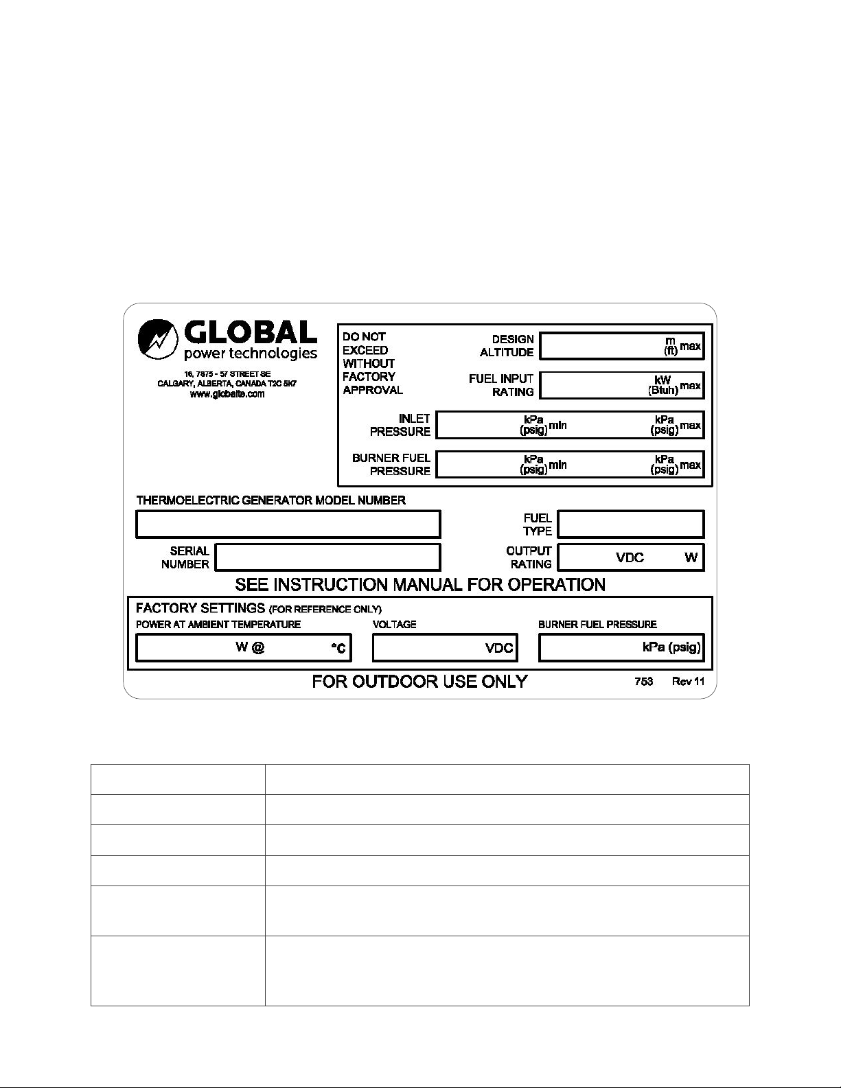
8. Do not exceed the fuel pressure stamped on the Thermoelectric Generator data plate without
factory approval. If fuel pressure exceeds reasonable levels, the power unit may be seriously and
permanently damaged.
9. The Thermoelectric Generator exhaust can be very hot. Do not touch any of the exhaust
components or bring exposed skin near hot exhaust gases.
10. If the Thermoelectric Generator has not been given enough time to cool, the spark electrode can
be dangerously hot.
11. The Thermoelectric Generator consists of some parts constructed from sheet metal. While every
effort is made to ensure that edges have been deburred when manufactured, sharp edges may
still exist. Exercise caution when handling. Wearing gloves is recommended.
12. When the Thermoelectric Generator is operating, surface temperatures of the unit can approach
temperatures close to 200°C. Avoid contact of skin and clothing with the surfaces of the
Thermoelectric Generator to avoid burns.
2. The Thermoelectric Generator, when installed, must be electrically grounded in accordance with
local codes, or in the absence of local codes, with the Canadian Electrical Code, CSA C22.1.

Global Power Technologies IMPORTANT SAFETY INSTRUCTIONS
05585 rev11 | Model 8550-SD Page 2 of 53
1.1 MANUAL ICONS AND SAFETY BANNERS
The following banners are used throughout this manual:
WARNING!
A banner with the word “WARNING!” below an icon with an exclamation point
within a red triangle contain important information that, if not adhered to, can
cause personal injury and/or property damage.
CAUTION!
A banner with the word “CAUTION!” below an icon with an exclamation point
within a red triangle contain important information that, if not adhered to, can
cause damage to the TEG.
NOTE: A banner with the word “NOTE:” contains supplemental information that provide
additional insight on specific topics within this manual.
1.2 COPYRIGHT, LIABILITY, AND CONTACT INFORMATION
For any technical issues or questions, contact:
Global Power Technologies – Head Office
#16, 7875 – 57 Street SE Phone: 1-403-236-5556
Calgary, Alberta Fax: 1-403-236-5575
Canada T2C 5K7 Customer Service/Technical Support: 1-403-720-1190
Copyright
Copyright© 2022 by Global Power Technologies (GPT). All rights reserved. No part
of this manual may be reproduced without permission in writing from GPT, except
by a reviewer who may quote brief passages or reproduce illustrations in a review
with appropriate credit; nor may any part of this manual be reproduced, stored in
a retrieval system, or transmitted in any form or by any means – electronic,
photocopying, recording, or otherwise – without prior permission in writing from
GPT.
Liability
Liability The user is expressly warned to consider and adopt all safety precautions
that might be indicated by the activities herein and to avoid all potential hazards.
The user assumes all risks in connection with such instructions. GPT shall not be
liable for any special, consequential, exemplary, or other damages resulting, in
whole or part, from the user’s use of, or reliance upon this material.
Comments
GPT has compiled this publication with care, but GPT does not warrant that the
information in this publication is free of errors. Comments, criticisms, and
suggestions regarding the subject matter are invited. Any errors or omissions in the
data should be brought to the attention of GPT. If required, affected pages will be
revised and issued.

Global Power Technologies GENERAL INFORMATION
05585 rev11 | Model 8550-SD Page 3 of 53
2GENERAL INFORMATION
A Thermoelectric Generator (TEG) is solid-state device that produces electrical power by directly
converting heat energy into electrical energy. It is a reliable, low-maintenance source of DC electrical
power for applications where regular utilities are unavailable or unreliable.
The Model 8550-SD TEG comes equipped with a 6720 Voltage Limiter.
A Cathodic Protection Interface is also available as an option to use with this generator.
Operation and service instructions for both the 6720 Voltage Limiter and the Cathodic Protection
Interface option are included in this manual.
The Thermoelectric Generator is designed FOR OUTDOOR USE ONLY.
2.1 TERMS AND ACRONYMS
The following terms and acronyms are used throughout this manual:
Thermoelectric Generator
(TEG)
A device that produces electrical power through the direct conversion
of heat energy to electrical energy.
GPT
Global Power Technologies
Power Unit
The hermetically sealed portion of the generator that contains the
thermoelectric materials.
Matched Load
A condition of load where the load voltage of the generator is one
half of the open circuit voltage.
Optimum Load
A condition of load where the power output of the generator is
maximized.
Power Conditioner
A broad term used to describe an electronic device attached to the
generator that converts, adjusts, limits, or otherwise conditions the
output power. This manual uses the terms “Power Conditioner” and
“Limiter” interchangeably.
Converter
An electronic device attached between the generator and load that
converts one level of DC voltage to another.
Limiter
An electronic device attached between the generator and load that
limits the voltage level. This manual uses the terms “Power
Conditioner” and “Limiter” interchangeably.
Heat Pipe
A hermetically sealed fluid filled heat transfer device, and its
associated cooling fins, used to cool the cold junctions of the Power
Unit.
Thermostat
A safety device used to shut down the TEG during a heat pipe
overtemperature event.
Rated Power
The power that the TEG will produce at standard temperature and
voltage.

Global Power Technologies GENERAL INFORMATION
05585 rev11 | Model 8550-SD Page 4 of 53
Set Power
The power level to which the Power Unit is set up at non-standard
temperatures so that it produces Rated Power when the temperature
returns to standard.
Thermal Cut-off (TCO)
A safety device used to shut down the TEG during a cabinet
overtemperature event.
2.2 DATA PLATE
The data plate shows important information about the TEG and can be used as a quick reference
point when performing service or contacting GPT. It is located on the inside of the cabinet door.
When contacting GPT, indicate both the complete Model Number and Serial Number of your TEG.
Figure 1 – Data Plate
The information indicated on the data plate are as follows:
Design Altitude Maximum permitted altitude that the TEG should be operated at.
Fuel Input Rating Maximum permitted energy rate to the generator.
Inlet Pressure Minimum and maximum levels of inlet fuel pressure permitted.
Burner Fuel Pressure Minimum and maximum levels of burner fuel pressure permitted.
TEG Model Number The TEG’s model number. Refer to the model tree on Figure 2for an
explanation of the model number.
Fuel Type
The type of fuel that the TEG’s fuel system is designed for and was
tested with.
L = Propane; N = Natural Gas

Global Power Technologies GENERAL INFORMATION
05585 rev11 | Model 8550-SD Page 5 of 53
Serial Number A unique number assigned to the TEG unit by GPT for traceability.
Output Rating Nominal power output of the TEG.
Factory Settings:
Power Unit at Ambient
Temperature
Power Unit power and temperature recorded during the factory
acceptance test. This is the maximum power unit power that can be
expected from the TEG under similar conditions.
Voltage Power unit voltage recorded during factory acceptance test.
Burner Fuel Pressure Burner fuel pressure recorded during factory acceptance test.
The Model 8550-SD TEG’s model number can be interpreted as follows:
Figure 2 – Model Number Explanation
CAUTION!
Use only the type of fuel that is indicated on the data plate.

Global Power Technologies INSTALLATION
05585 rev11 | Model 8550-SD Page 6 of 53
3INSTALLATION
WARNING!
Read all application documentation, including the documentation for equipped
options BEFORE STARTING ASSEMBLY AND INSTALLATION, or performing service
check and maintenance on the Thermoelectric Generator.
3.1 PREPARATION
3.1.1 BASE
Before beginning assembly, ensure that the base where the TEG will be placed is level and does not
deviate by more than 3° (0.5 inch per foot or 50 mm per meter).
The Model 8550-SD TEG has an optional stand that allows optimal airflow around the TEG and
convenience for operators to perform service checks. If you opted not to purchase the stand, prepare
a platform or stand to mount the TEG on. The TEG should be mounted high enough to prevent
flooding or heavy snowfall from interfering with the flow of cooling or intake air around the TEG. We
recommend a stand that is 36 inches (91 cm) above the ground. Anchor the stand to the base so that
it remains stable through inclement weather.
3.1.2 LOCATION
If the TEG will be installed near a building or large objects that may obstruct the flow of wind, choose
a site on the windward side at least 45 feet (14 m) away from the building or object, or on the roof if
possible.
Always follow local regulations when placing the TEG near buildings and fuel tanks.
3.1.3 FUEL SUPPLY
The fuel system on each TEG unit is designed for either propane or natural gas. Check the Data Plate
on inside of the TEG cabinet to verify the type of fuel that is compatible with your TEG.
When preparing the fuel supply to the TEG:
1. Make sure that the fuel is free of moisture or any other type of contamination.
If the fuel is expected to contain moisture or other contaminants, use a filtering or fuel
conditioning system. Consult GPT for more information.
2. Make sure that the fuel supply pressure never exceeds 25 psi (172 kPa).
If the supply fuel pressure is expected to vary significantly, use an additional primary
regulator to ensure that the input pressure to the Burner Fuel Pressure Regulator stays
relatively constant.
3. Make sure that the fuel is appropriate to the environment. If using propane, make the following
adjustments if necessary:
In environments with temperatures that fall below 5°C (41°F), use pure methyl hydrate in
the ratio of 1:800 by volume as an antifreeze additive.
NOTE: Moisture in the propane may freeze at temperatures below 5°C (41°F).

Global Power Technologies INSTALLATION
05585 rev11 | Model 8550-SD Page 7 of 53
In environments with temperatures that fall below -20°C (-4°F), use a liquid withdrawal and
vaporization system. Consult GPT for suitable designs before installation.
The fuel consumption of a Model 8550 TEG operating at rated power under standard
temperatures conditions is as follows:
Propane: 76.0 L/day (20.1 US gal/day)
Natural Gas:
48.0m
3
/day (1695 Sft
3
/day)
3.1.4 GASEOUS FUEL STANDARDS
Gaseous fuels provided to Global Power Technologies’ thermoelectric generators (TEGs)(1):
1. Shall not contain any particulates larger than 30 µmm diameter, including but not limited to
sand, dust, gums, crude oil, and impurities.
2. Shall not have a hydrocarbon dew point in excess of 0°C (32°F) at 170 kPag(25 psig).
3. Shall not contain more than 115 mg/Sm3 (2) (approx. 170 ppm) of H2S.(3)
4. Shall not contain more than 60 mg/Sm3(approx. 88 pmm) of Mercaptan Sulphur.
5. Shall not contain more than 200 mg/Sm3(approx. 294 ppm) of total Sulphur.
6. Shall not contain more than 10% [CO2] and/or [N2] by volume, nor vary by more than ± 1% [CO2]
and/or [N2] during operation.
7. Shall not contain more than 120 mg/Sm3 of water vapour.
8. Shall not contain more than 1% by volume of free oxygen.
9. Shall have a nominal heating value (HHV) of:
Natural Gas: 37 MJ/m³ (1000 BTU/ cu.ft.) (1)
Propane/LPG: 93 MJ/m³ (2500 BTU/ cu.ft.) (1)
Butane: 122 MJ/m3(3300 BTU/cu.ft.) (1)
10. Shall not exceed 60°C (140°F) in temperature.
NOTES:
(1) For gaseous fuels outside of these specifications, please contact Global Power
Technologies.
(2) At 1 atm and 15°C (59°F).
(3) Contact local representative or Global Power Technologies if H2S concentration is
greater than 170 ppm.

Global Power Technologies INSTALLATION
05585 rev11 | Model 8550-SD Page 8 of 53
3.2 UNPACKING AND MOUNTING
To prepare for assembly and installation, you will need the following tools and equipment:
Two voltmeters with leads and clips able to measure the following ranges:
•0-30 ±0.1 V
•0-30 ±0.1 mV
•Customer Load Voltage
Two small adjustable wrenches that can open to 5/8 inch (16 mm)
A medium flat blade screwdriver
A fine flat blade screwdriver
A Phillips head screwdriver
A 3/8-inch wrench
Wire strippers
Teflon thread sealant tape
WARNING!
Check the TEG for any signs of damage before beginning assembly and installation.
Some damages can make the TEG inoperable. Consult Global Power Technologies
before operating a TEG with any signs of damage.
Do not discard the shipping crate until the TEG is fully
operational. Before removing the TEG from the crate:
1. Check the TEG for any damage that may have occurred
during shipping. If the TEG shows any sign of damage,
contact Global Power Technologies to report it. Do not
proceed with the installation.
2. Check and re-tighten any bolts that may have loosened.
3. Remove the tie wraps that clamp the ends of the heat
pipes to the support ring.
CAUTION!
Failure to remove the tie wraps can cause the heat pipes to crack when they
expand.
4. Once the tie wraps have been removed, lift the TEG out of the crate. This must be done by two or
more persons. Use the upper ring around the heat pipes, or the frame where the ring is
mounted, as lifting points.
NOTE:
If lifting with slings, secure the slings to the upper ring in at least three points in equal
distance from one another to ensure that the TEG does not swing or rock during
lifting.
5. Locate the installation kit with the following parts:
Mounting Bolts – 1/4 in x 3/4 in, with nuts and washers (x4)
Stand Grounding Set – 3/8 in x 2 in bolt with nuts and washers (x1)
Spare Thermal Cut-off (x1)
Figure 3 – Heat Pipe Tie Wrap

Global Power Technologies INSTALLATION
05585 rev11 | Model 8550-SD Page 9 of 53
The following parts can be found inside the TEG cabinet:
Shutdown Relay Assembly, includes Thermal Cut-off and Thermocouple
Spark Igniter Electrode
6. If the TEG was shipped with the optional TEG stand, assemble the stand as shown on Figure 4
and install it on a stable, level base. If the TEG does not have the stand option and a custom
platform or stand has already been installed, confirm that the stand is bolted securely to the
base, level and does not deviate by more than 3°, then proceed to the next step.
Figure 4 – TEG Stand
WARNING!
Operation of TEG on an unstable or non-level base or in locations where cooling air
flow may be obstructed will cause overheating of the TEG.
3.3 INSTALLING THE RELAY ASSEMBLY
The Shutdown Relay Assembly is shipped inside the TEG cabinet. To install:
1. Thread the male end of the Relay Assembly into the bottom of the Shut-off Valve on the Fuel
System. Tighten the joint using a 3/8-inch wrench. DO NOT OVERTIGHTEN.
2. Position the Relay with the female end of the assembly pointed towards the back of the cabinet.
3. Carefully fit the male end of the thermocouple into the female end on the Relay Assembly.
Tighten the threads using a 3/8-inch wrench, being CAREFUL NOT TO OVERTIGHTEN.

Global Power Technologies INSTALLATION
05585 rev11 | Model 8550-SD Page 10 of 53
NOTE:
Maintain a large radius on the bends of the thermocouple. Be careful NOT TO BREAK
the thermocouple at the burner joint.
4. Verify the connections of the Thermal Cut-off that is in line with the red wire on the Shutdown
Relay Assembly. Verify both the mechanical integrity of the connections and the electrical
continuity of the Thermal Fuse within.
Figure 5 – Installation of Spark Igniter and Fuel Line
3.4 INSTALLING THE SPARK IGNITER ELECTRODE
To install the Spark Igniter Electrode:
1. Slide the Spark Igniter Electrode through the fitting on the bottom of the burner until it touches
inside, then pull back by approximately 1/8 inch (3 mm). This should leave 2.24 to 2.40 inches (57
to 61 mm) extruding beyond the fitting, refer to Figure 5.
2. Gently tighten the nut on the fitting to maintain the position of the electrode.
3. Connect the terminal lug of the high-voltage cable to the end of the Spark Igniter Rod.
3.5 CONNECTING THE FUEL SUPPLY
WARNING!
Use only the type of fuel indicated on
the data plate. See Section 3.2.
The
maximum inlet pressure to the TEG must never exceed 25 psi (172 kPa).
Before connecting the fuel supply to the TEG, review Section 4.1.3 and ensure that all necessary
precautions have been made based on the fuel supply used and the environmental conditions.

Global Power Technologies INSTALLATION
05585 rev11 | Model 8550-SD Page 11 of 53
Connect the fuel supply as follows:
1. Install a fuel shut-off valve between the TEG and the fuel supply.
NOTE:
Follow local regulations when installing fuel piping.
2. Inspect fuel lines and fittings to ensure that they are free of foreign material.
3. Remove the plastic protective cap from the TEG’s 1/4-inch NPT male connector.
4. Apply Teflon tape, or other thread sealant, on the male connector as illustrated in Figure 6 to
minimize fuel line contamination.
5. Connect the fuel line and check all joints for leaks using a commercial leak detector fluid such as
Snoop®.
6. Purge fuel supply lines to the TEG of all air.
3.6 ADJUSTING FOR ALTITUDE
The burner fuel pressure supplied on the TEG, and marked on the data plate, is set for the factory
altitude or site elevation of 2460 ft (750 m). At the factory’s elevation, the fuel pressure should be in
the range of 16 to 22 psi (110 to 150 kPa) for propane or 6 to 10 psi (41 to 69 kPa) for natural gas.
If the TEG’s installation site is at a similar altitude, check the burner fuel pressure and confirm
that is has not changed from the factory setting as marked on the data plate.
If the TEG’s installation site is at a different altitude, adjust the burner fuel pressure as follows:
a) Determine the altitude of the installation site and mark that number on the graph in
Figure 7.
b) From the marked altitude on step a), follow the line vertically towards the curve and stop
when you touch the curve. This is the point to where you will adjust your fuel pressure.
Figure 6 – Applying Thread Sealant

Global Power Technologies INSTALLATION
05585 rev11 | Model 8550-SD Page 12 of 53
c) From the factory altitude marked on the curve, measure the amount of pressure that
adjustment is required for your site’s altitude by counting vertically from the Factory
Elevation mark at 0 psi/kPa. Enter this number on the Start-up Data Sheet.
For example:
If your TEG will be installed at a site with an altitude of 2460 ft (750 m), increase your
burner fuel pressure by 2.61 psi (18 kPa) from the factory setting.
Figure 7 – Altitude Adjustment

Global Power Technologies START-UP AND OPERATION
05585 rev11 | Model 8550-SD Page 13 of 53
4START-UP AND OPERATION
4.1 IGNITION AND START-UP PROCEDURE
WARNING!
Before
initiating start-up, make sure that the Power Unit output wires are
connected to
the 6720 Voltage Limiter input.
Before attempting to start the Model 8550-SD TEG, make sure to review and understand the
Electrical Output Characteristics in Figure 31 and the Terms and Acronyms in Section 3.1.
Before starting the TEG:
Ensure that the fuel system has been properly installed as outlined in Section 4.5.
Review the Basic Wiring Diagram in Figure 32, identify the various components and find their
location on the TEG system.
Review the operations of the 6720 Voltage Limiter in Section 8 and understand how to adjust the
voltage.
Ensure that the Customer Load is disconnected.
Remove both the positive and negative load wires at Terminals 2 and 4 of Terminal Block TB-1.
This will also need to be done for power adjustments.
NOTE:
Use the Start
-up Data Sheet located at the end of this manual during the start-up process.
It
helps simplify starting, heating up, and making power adjustments.
4.1.1 DETERMINE SET POWER
Determine the required Set Power before proceeding with Start-up. Set Power is the power to which
the TEG must be set at your ambient conditions so that it generates Rated Power when the ambient
conditions return to standard. To determine Set Power:
1. Refer to Table 1or Table 2and follow these steps to determine the Corrected Air Temperature:
a) In the first row of figures, where ambient air temperatures at 0 Wind Speed are listed, find
the column with the current ambient temperature of the TEG’s installation site.
b) Move down the column to find the cell in the same row as the expected wind speed.
c) The cell where Air Temperature and Wind Speed meet is the corrected air temperature.
For example, if the air temperature is 50°F (10°C) and the wind speed is 12.4 mph (20 kph), then
the corrected air temperature is 27°F (-3°C).
Record the corrected air temperature in the Start-up Data Sheet.

Global Power Technologies START-UP AND OPERATION
05585 rev11 | Model 8550-SD Page 14 of 53
Air Temperature (°C)
Wind Speed (kph)
0
-20
-15
-10
-5
0
5
10
15
20
25
30
35
40
45
50
5
-27
-21
-16
-11
-6
-1
5
10
16
21
27
32
37
42
47
10
-34
-27
-21
-15
-9
-3
2
9
13
18
24
29
35
40
46
15
-40
-32
-24
-18
-12
-6
-1
4
10
15
21
26
32
37
42
20
-41
-35
-29
-21
-14
-8
-3
2
8
13
19
24
30
35
41
25
-44
-37
-31
-23
-16
-10
-5
0
6
11
17
22
28
33
38
30
-46
-39
-33
-25
-18
-12
-7
-1
4
9
15
20
26
31
37
35
-47
-40
-34
-26
-19
-13
-8
2
3
8
14
19
25
30
36
40
-49
-42
-35
-22
-20
-14
-9
-3
2
7
13
18
24
29
35
Table 1 – Corrected Air Temperature for Wind (in km per hour and °C)
Air Temperature (°F)
Wind Speed (mph)
0
-4
5
14
23
32
41
50
59
68
77
86
95
104
113
122
3.1
-17
-6
3
12
21
30
41
50
61
70
81
90
99
108
117
6.2
-29
-17
-6
5
16
27
36
48
55
64
75
84
95
104
115
9.3
-40
-26
-11
0
10
21
30
39
50
59
70
79
90
99
109
12.4
-42
-31
-20
-6
7
18
27
36
46
55
66
75
86
95
106
15.5
-47
-35
-24
-9
3
14
23
32
42
52
63
72
82
91
100
18.6
-51
-38
-27
-13
0
10
19
30
39
48
59
68
79
88
99
21.7
-53
-40
-29
-15
-2
9
18
28
37
46
57
66
77
86
97
24.8
-56
-44
-3
-8
-4
7
16
27
35
45
55
64
75
84
95
Table 2 – Corrected Air Temperature for Wind (in miles per hour and °F)
2. Using the corrected air temperature as determined in Step 1, find the required Set Power using
the graph on Figure 8. To do this:
a) Find the corrected temperature along the bottom of the graph labeled “Ambient
Temperature”.
b) From that number, go up the graph and stop when the path touches the curve (diagonal
line).
c) From that intersection, follow a line to the numbers on the left labeled “Set Power”.
Continuing with the previous example, if the corrected air temperature is 27°F (-3°C), based on
the graph on Figure 8, the Set Power is 620 W.
3. Enter this number in the Start-Up Data Sheet. Do not operate the TEG beyond this number.

Global Power Technologies START-UP AND OPERATION
05585 rev11 | Model 8550-SD Page 15 of 53
Figure 8 – Power as a Function of Ambient Temperature
WARNING!
Do not operate the TEG above the curve on
Figure 8. This may result in damage to
the Power Uni
t.
4.1.2 START-UP
Before starting up, connect a voltmeter across terminals 6 (+) and 4 (-) of TB-1. This will measure the
Power Unit voltage during start-up.
Connect the second voltmeter across Terminals 6 (+) and 7 (-) of TB-1. This will measure the Power
Unit current (1 mV = 1 Amp).
Follow these steps to start-up the Model 8550-SD TEG:
1. Turn on the fuel supply to the TEG and observe the fuel pressure at the fuel pressure gauge.
Refer to the Start-up Data Sheet and compare the observed fuel pressure to the adjusted fuel
pressure as determined in Section 4.6.
If the pressure is lower, increase it by turning the screw on the pressure regulator clockwise
until it reaches the correct pressure.

Global Power Technologies START-UP AND OPERATION
05585 rev11 | Model 8550-SD Page 16 of 53
If the pressure is higher, decrease it by turning the screw on the pressure regulator
counterclockwise and venting the pressure through the burner by momentarily pressing the
button on the Automatic Shut-off Valve.
Figure 9 – Fuel System Components
2. Check the operation of the Ignition System by shorting together the terminals of the Pressure
Switch. The Spark Igniter should produce a strong and rapid clicking sound. If it does not start
clicking, troubleshoot the system as indicated in Section 6.6.
3. Check that the Burner Run Valve is closed (down).
4. Open the Automatic Shut-Off valve by pressing the button with one hand. Keep this button
pressed. Do not release until instructed (Step 8).
The Spark Igniter should start clicking followed by a series of popping sounds from the unit as the
burner ignites. The Power Unit voltage will start to rise slightly.
5. Continue to hold down the button.
If ignition does not occur within 5 seconds, release the button and check to make sure that
fuel is reaching the burner. Confirm that the fuel lines were purged of air.
If fuel is reaching the burner, refer to Section 6.6 to troubleshoot the Ignition System.
6. As soon as combustion begins, slowly open the Burner Run Valve.
The burner sounds will change and the Power Unit voltage will rise more rapidly.
7. Continue to hold down the button.
Table of contents
Other Global Portable Generator manuals

Global
Global MX PrimeGen User manual

Global
Global 5030 User manual

Global
Global 5120 User manual

Global
Global 8550-RU User manual

Global
Global 716174 User manual

Global
Global P-5100 User manual

Global
Global Sentinel User manual

Global
Global S-8500 User manual

Global
Global 1120 User manual

Global
Global MX PrimeGen Installation and user guide
Popular Portable Generator manuals by other brands

Teleco
Teleco Telair ENERGY 2510D Use and maintenance manual and instructions for installation

Noise
Noise LSS-6000 Series instruction manual

Westinghouse
Westinghouse WGen11500TFc user manual

Stanley
Stanley GTR20B01 user manual

Shindaiwa
Shindaiwa DGW300MS Owner's and operator's manual

Honeywell
Honeywell 2000 Watt Operator's manual