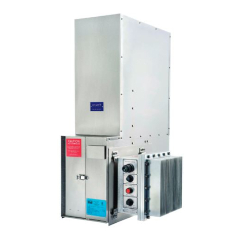
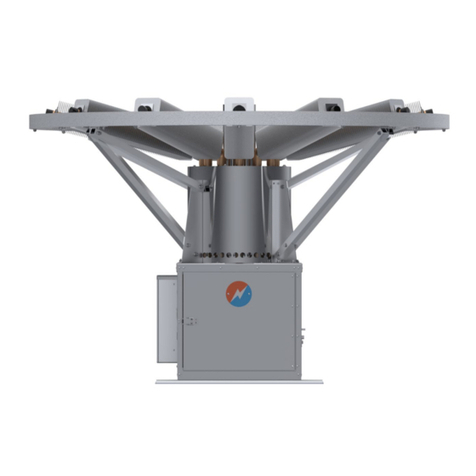
Global P-5100 User manual

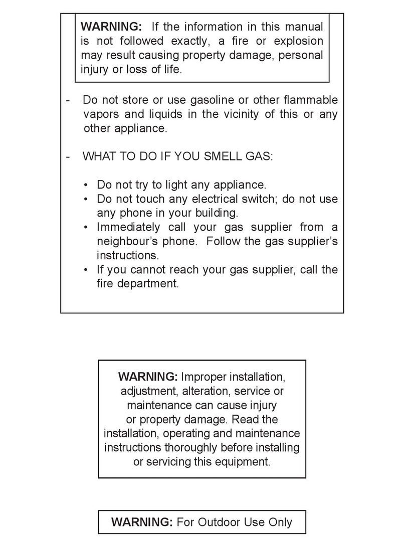
WARNING
FIRE OR EXPLOSION HAZARD
Failure to follow safety warnings exactly could result
in serious injury, death, or property damage.
•
Do not store or use gasoline or other flammable
vapors and liquids in the vicinity of this or any other
appliance.
- Do not try to light any appliance.
- Do not touch any electrical switch; do not use any
phone in your building.
- Leave the building immediately.
- Immediately call your gas supplier from a
neighbor’s phone. Follow the gas supplier’s
instructions.
- If you cannot reach your gas supplier, call the fire
department.
WARNING
FIRE, EXPLOSION, AND ASPHYXIATION HAZARD
Improper adjustment, alteration, service, maintenance,
or installation can cause serious injury or death.
Read and follow installations and precautions in User’s
Information Manual provided with this appliance.
Installation and service must be performed by a
qualified service agency or the gas supplier.
WARNING: For outdoor use only.
NOTICE TO INSTALLER: These instructions shall be left with the consumer.
NOTICE TO CONSUMER: You must read all instructions in the manual and must keep all manuals for
future reference.

AVERTISSEMENT
RISQUE D’INCENDIE OU D’EXPLOSION
Si les consignes de sécurité ne sont pas suivies à la lettre,
cela pourrait entraîner une utilisation dangereuse, la
mort, de graves blessures ou des dommages matériels.
•
Ne pas entreposer ni utiliser d’essence ou d’autres
vapeurs et liquides inflammables à proximité de cet
appareil ou n’importe quelle application.
- Ne mettre en marche aucun appareil.
- Ne toucher aucun interrupteur électrique; ne pas
utiliser de téléphone dans le bâtiment.
- Quitter le bâtiment immédiatement.
- Appeler immédiatement le fournisseur de gaz en
utilisant le téléphone d’un voisin. Suivre les
instructions du fournisseur de gaz.
- Si le fournisseur de gaz n’est pas accessible, appeler
le service d’incendie.
AVERTISSEMENT
RISQUE D'INCENDIE, D'EXPLOSION ET D'ASPHYXIE
Si un réglage, une modification, une réparation, en entretien
ou l’installation est effectué de façon inadéquate, cela
pourrait causer de graves blessures ou la mort.
Lire et suivre les instructions et les précautions fournies dans
le manuel de l’utilisateur accompagnant cet appareil.
L’Installation et l’entretien doivent être effectués par un
installateur ou une entreprise d’entretien qualifié, ou le
fournisseur de gaz.
AVERTISSEMENT: Utiliser uniquement à l'extérieur.
AVIS À L'INSTALLATEUR: Ces instructions doivent être remises au consommateur.
AVIS AU CONSOMMATEUR: Vous devez lire toutes les instructions du manuel et conserver tous les
manuels pour référence future.

62128 Rev 12
P-5100 THERMOELECTRIC
GENERATOR
Operating Manual
#16, 7875 - 57th Street SE
Calgary, Alberta Canada T2C 5K7
Main: +1 403 236 5556
Fax: +1 403 236 5575
www.globalte.com


Global Power Technologies 62128 Rev12 I
TABLE OF CONTENTS
1ABOUT THIS MANUAL ...................................................................................... 1
1.1 HEALTH AND SAFETY .................................................................................. 1
1.2 TECHNICAL TERMS ..................................................................................... 4
2QUICK START PROCEDURE ............................................................................... 6
2.1 INSTALLATION........................................................................................... 6
2.2 START UP.................................................................................................. 6
2.3 ADJUSTMENT............................................................................................. 7
2.4 PERFORMANCE LOG .................................................................................... 7
3TECHNICAL SPECIFICATIONS ........................................................................... 8
3.1 OVERVIEW ................................................................................................ 8
3.2 OPTIONS................................................................................................... 8
3.3 WEIGHTS AND MEASURES ..........................................................................10
3.4 SPARK IGNITION SYSTEM...........................................................................11
3.5 DATA PLATE .............................................................................................11
3.6 FUEL CONSUMPTION..................................................................................13
3.7 STANDARD SPECIFICATION FOR GASEOUS FUEL............................................13
4PROCESS DESCRIPTION .................................................................................14
4.1 MODEL P-5100 THERMOELECTRIC GENERATOR..............................................14
4.2 LIMITER CONVERTER .................................................................................19
4.3 OPTIONAL CATHODIC PROTECTION INTERFACE SYSTEM .................................21
4.4 OPTIONAL REMOTE START (TEG CONTROLLER)..............................................22
4.5 OPTIONAL 48 VDC CONVERTER.....................................................................23
4.6 OPTIONAL VSR TERMINAL BLOCK.................................................................23
5INSTALLATION ..............................................................................................24
5.1 PRECAUTIONS ..........................................................................................24
5.2 TOOLS REQUIRED .....................................................................................24
5.3 UNPACKING..............................................................................................24
5.4 ASSEMBLING ............................................................................................25
5.5 MOUNTING...............................................................................................26
5.6 SUPPLYING FUEL .......................................................................................27
5.7 CONNECTING CUSTOMER LOAD...................................................................29
5.8 INSTALLATION OF OPTIONAL CP INTERFACE SYSTEM .....................................32
6STARTUP AND SHUTDOWN..............................................................................34
6.1 BEFORE STARTING ....................................................................................34
6.2 TEG START-UP ..........................................................................................34

Global Power Technologies 62128 Rev12 II
6.3 SHUTDOWN..............................................................................................34
7POWER OUTPUT EVALUATION ..........................................................................35
7.1 REQUIRED VSET OR SET-UP POWER AT SITE ...................................................35
7.2 CHECKING VSET OR SET-UP POWER ..............................................................37
8ADJUSTMENT AND TUNING .............................................................................40
8.1 POWER OUTPUT TUNING ............................................................................40
8.2 LIMITER CONVERTER ADJUSTMENT ..............................................................45
8.3 ADJUSTMENT OF OPTIONAL CP INTERFACE SYSTEM .......................................47
8.4 ADJUSTMENT OF OPTIONAL REMOTE START SYSTEM (TEG CONTROLLER) ..........49
8.5 ADJUSTMENT OF OPTIONAL 48VDC CONVERTER..............................................49
9MAINTENANCE ..............................................................................................50
9.1 RECOMMENDED PERIODIC MAINTENANCE.....................................................50
9.2 FUEL SYSTEM MAINTENANCE ......................................................................52
9.3 BURNER MAINTENANCE..............................................................................54
9.4 SPARK IGNITION SYSTEM MAINTENANCE......................................................56
9.5 LIMITER CONVERTER EXAMINATION.............................................................61
9.6 POWER UNIT EXAMINATION........................................................................61
10 TROUBLESHOOTING.......................................................................................64
11 PARTS LISTS.................................................................................................66
11.1 MODEL P-5100 TEG ...................................................................................67
11.2 MODEL P-5100 BURNER .............................................................................70
11.3 MODEL P-5100 FUEL SYSTEM ......................................................................72
11.4 MODEL P-5100 OPTIONAL STAINLESS-STEEL FUEL SYSTEM .............................73
11.5 MODEL P-5100 ELECTRICAL ........................................................................74
12 CATHODIC PROTECTION OPTION .....................................................................76
12.1 INTRODUCTION ........................................................................................76
12.2 CONFIGURATIONS.....................................................................................77
12.3 OPTIONAL CP SYSTEM PARTS TABLE ............................................................78
13 HEAT RECOVERY SYSTEM (HRS) OPTION ...........................................................80
13.1 INTRODUCTION ........................................................................................80
13.2 INSTALLATION..........................................................................................80
13.3 TEG OPERATION........................................................................................80
13.4 MODEL P-5100 HRS CONFIGURATION PARTS .................................................81
13.5 MODEL P-5100 HRS BURNER PARTS .............................................................82
14 TEG PERFORMANCE LOG .................................................................................83

Global Power Technologies 62128 Rev12 III
TABLE OF FIGURES
Figure 1 – Overall Dimensions of the P-5100 TEG ......................................................................................................10
Figure 2 - Data Plate....................................................................................................................................................12
Figure 3 - P-5100 TEG General Assembly....................................................................................................................14
Figure 4 – P-5100 Fuel System General Assembly......................................................................................................15
Figure 5 – Burner General Assembly ..........................................................................................................................17
Figure 6 – Model P-5100 Power Unit Electrical Output Characteristics.....................................................................18
Figure 7 – L/C General Assembly ................................................................................................................................20
Figure 8 - CP Interface System General Assembly......................................................................................................22
Figure 9 - TEG Controller Assembly ............................................................................................................................23
Figure 10 – Assembling the P-5100 TEG .....................................................................................................................25
Figure 11 – Model P-5100 Mounting Dimensions ......................................................................................................26
Figure 12 – Applying Thread Sealant ..........................................................................................................................27
Figure 13 – Setting-up the P-5100 TEG.......................................................................................................................28
Figure 14 - Wiring Diagram P-5100 for 12 or 24 V......................................................................................................30
Figure 15 - Wiring Diagram P-5100 TEG for 12 or 24V with optional TEG Controller ................................................31
Figure 16 - Customer Load Connections.....................................................................................................................32
Figure 17 – CP Installation ..........................................................................................................................................33
Figure 18 - VSET and Setup Power Versus Ambient Temperature ...............................................................................37
Figure 19 - VSET Versus Time After Ignition, Typical Response....................................................................................38
Figure 20 - Change in Fuel Gauge Pressure Versus Elevation Above Mean Sea Level ...............................................40
Figure 21 - Change in VSET Versus Air-Shutter Adjustment .........................................................................................41
Figure 22 - Change in VSET Versus Fuel Pressure Adjustment .....................................................................................44
Figure 23 - CP Interface System, Series Wiring Diagram ............................................................................................48
Figure 24 - CP Interface System, Parallel Wiring Diagram..........................................................................................48
Figure 25 – Pressure Regulator...................................................................................................................................53
Figure 26 - Burner Assembly Cross Section ................................................................................................................55
Figure 27 - Electrode Protrusion from Air Box Lid ......................................................................................................59
Figure 28 - Solenoid Valve Cable Plug Connections....................................................................................................60
Figure 29 - Momentary Open Circuit Diagram ...........................................................................................................62
Figure 30 - Model P-5100 TEG ....................................................................................................................................67
Figure 31 - Model P-5100 Burner ...............................................................................................................................70
Figure 32 - Model P-5100 Fuel System .......................................................................................................................72
Figure 33 - Model P-5100 SS Fuel System...................................................................................................................73
Figure 34 - Model P-5100 Electrical............................................................................................................................74
Figure 35 - Cathodic Protection Interface Cabinet .....................................................................................................76
Figure 36 - Cathodic Protection System Parts Identification......................................................................................78
Figure 37 - HRS Option Overview ...............................................................................................................................80
Figure 38 – P-5100 HRS Configuration........................................................................................................................81
Figure 39 - Model P-5100 HRS, Burner .......................................................................................................................82


ABOUT THIS MANUAL
Global Power Technologies 62128 Rev12 Page 1
1ABOUT THIS MANUAL
This manual provides instructions for the operation and maintenance of the model P-5100
Thermoelectric generator.
Correct operation and maintenance according to this manual is critical for proper equipment
function and safety. Keep the following in mind when using these instructions.
Warnings
Throughout this manual you will notice paragraphs preceded by the text Warning. It is
imperative that the advice in these paragraphs be adhered to, as failure to do so may result
in personal injury or death and possible damage to the equipment.
WARNING!
Before any work begins on the Thermoelectric
Generator, please read this Operating Manual
thoroughly.
WARNING!
The Thermoelectric Generator consists of sub-systems
that combust gaseous fuel and others that consume
excess power through resistors, all of which can pose
high surface temperature hazards. Operators and
service personnel should avoid indicated areas of the
generator to avoid burns or clothing i
gnition when in
operation or cooling down.
WARNING!
Any guard or other protective device removed for
servicing the Thermoelectric Generator must be
replaced prior to operating the appliance.
WARNING!
Installation and repair should be performed by a
qualified service person. The Thermoelectric Generator
should be inspected before use and at least annually
by a qualified service person. More frequent cleaning
may be required as necessary. It is imperative that
control compartment, burner
s and circulating air
passageways of the appliance be kept clean.
WARNING!
Inspect and check all gas connections for leaks using
a commercially available liquid leak detection fluid
after installation or service to any part of the fuel
system.
Remedy any fuel system leaks prior to
starting the Thermoelectric Generator.

ABOUT THIS MANUAL
Global Power Technologies 62128 Rev12 Page 2
WARNING!
This device contains electrical and gas related safety
devices as identified throughout this manual.
Tampering or rendering inoperative any of these
safety devices may result in personal injury or death
and possible damage to the equipment and is not
permitted under any circumstances.
WARNING!
The Thermoelectric Generator is designed to combust
gaseous fuels which will result in combustion products
of heat,
carbon dioxide and water vapor and may
contain traces of Carbon Monoxide, unburnt
Hydrocarbons and Nitrous Oxides. Emissions from
combustion will depend on generator set-
up and
operation as well as the composition of the gas feed.
It is imperative that the
se instructions be followed, and
that gas supplied meets Global Power Technologies’
gas specification.
WARNING!
Fuel supplied to the TEG must not contain liquids.
Liquid hydrocarbons in the fuel supply pose a risk of
fire and may result in serious damage to the TEG and
danger for the operator.
WARNING!
Do not exceed the fuel pressure print
ed on the TEG
data plate without factory approval. If fuel pressure
exceeds reasonable levels, the power unit may be
seriously and permanently damaged.
WARNING!
The TEG exhaust can be very hot. Do not touch any
of the exhaust components or bring exposed skin near
hot exhaust gases. Do not leave the combustion
analyzer probe in the TEG exhaust –
it may be
damaged by extreme heat.
WARNING!
Exhaust gases are toxic and should not be inhaled.
The P-5
100 TEG is strictly an outdoor device and
should never be used indoors. Avoid inhaling exhaust
gases while working around or above the TEG.
WARNING! If TEG has not been given
enough time to cool, the
spark electrode can be dangerously hot.

ABOUT THIS MANUAL
Global Power Technologies 62128 Rev12 Page 3
Cautions
Throughout this manual you will notice paragraphs preceded by the text Caution. It is
imperative that the advice in these paragraphs be adhered to, as failure to do so may result
in damage to the equipment.
CAUTION!
The Thermoelectric Generator and its individual shutoff
valve must be disconnected from the gas supply piping
system during any pressure testing of that system at
test pressures in excess of 3.5 kPa (1/2 psig).
The Thermoelectric Generator must be isolated from
the gas supply piping system by closing its individual
manual shutoff valve during any pressure testing of
the gas supply piping system at test pressures equal
to or less than 3.5 kPa (1/2 psig).
CAUTION!
The Thermoelectric Generator consists of some parts
constructed from sheet metal. Every effort is made to
ensure that edges have been deburred when
manufactured, sharp edges may still exist. Caution
must be exercised when handling and use of gloves is
advised.
CAUTION!
If a hose assembly is used to connect the
Thermoelectric Generator to the gas supply piping
system, inspect the hose assembly before each use of
the Thermoelectric Generator.
The hose assembly must be replaced prior to the
appliance being put into operati
on if there is evidence
of excessive abrasion or wear, or if the hose is
damaged.
The replacement hose assembly shall be that specified
by the manufacturer.
CAUTION!
Properly locating the hose out of pathways where
people may trip over it or in
areas where the hose
may be subject to accidental damage.
CAUTION!
When the TEG is operating, surface temperatures of
the unit can approach temperatures close to 200°C.
Avoid contact of skin and clothing with the surfaces of
the TEG to avoid burns.

ABOUT THIS MANUAL
Global Power Technologies 62128 Rev12 Page 4
Trained Operators
Personnel performing installation, operation, and maintenance work should be properly
trained in such functions.
An operator should be familiar with technical terminology. Terms of particular significance,
defined for the model P-5100, are as follows:
Thermoelectric Generator (TEG): A device that produces electrical power through the
direct conversion of heat energy to electrical energy.
Power Unit (PU): The hermetically sealed portion of the TEG that contains the
thermoelectric materials and cooling fins.
Rated Power: Model P-5100 TEG produces 100 W when operating in an ambient
temperature of 20°C (68°F). With the fuel flow held constant TEGs operating in ambient
temperatures higher than 20°C (68°F) will see power output efficiency reduce, 0.4 W per °C
(0.2 W per °F) of temperature change up to a maximum ambient temperature of 55°C
(130°F). Conversely for temperatures lower than 20°C (68°F) power output efficiency will
increase by 0.4 W per °C (0.2 W per °F) of temperature change.
Set-up Power: Power from the power unit for a specific ambient temperature. It is derived
from voltage across a precision load, also known as VSET.
Set-up Voltage: VSET Voltage from the power unit for a specific ambient temperature, which
is proportional to set-up power. Fuel flow to the burner is adjusted so that proper voltage
exists, necessary temperature difference within the power unit maintained, to deliver
required power.
Open Circuit Voltage: Voltage at the terminals of the power unit when no current is flowing,
i.e., open circuit, which is related to the temperature across the thermoelectric materials
inside the power unit.
When a power unit lead is suddenly disconnected, breaking the circuit to the load, the voltage
measured across the power unit leaps up to a new value. This is known as the momentary
open circuit voltage (VOC).
Measured VSET: VSET measured across the precision load on the output of the electronics
without a customer load connected using a voltmeter.
Required VSET: VSET needed to achieve rated power for the present ambient temperature.
CP (Cathodic Protection): Thermoelectric generators are used in impressed current
systems for Cathodic corrosion protection of metallic structures such as pipelines.

ABOUT THIS MANUAL
Global Power Technologies 62128 Rev12 Page 5
CP Interface System: An assembly of electrical components system that acts as an
interface between the TEG and the CP load, which also provides for adjustment and
monitoring of power to the CP load.
Limiter Converter (L/C): A specific electronic device attached between the generator and
the load that converts one level of DC voltage to another and limits the power unit voltage.
Manual Shutoff Valve: A manually operated valve in the gas line for completely turning on
or shutting off the gas supply to the TEG.
Solenoid Valve (SV): A electrically actuated valve that controls the fuel gas supply to the
burner. This valve is operated by the Spark Ignition (SI) Module.
Spark Ignition (SI): The method and system used to ignite the TEG. Refer to section 4.1.2
for details.

QUICK START PROCEDURE
Global Power Technologies 62128 Rev12 Page 6
2QUICK START PROCEDURE
This section gives the key steps for setting-up the TEG. It is for the operator who is already
familiar with operating the TEG, having successfully completed Global Power Technologies
(GPT) TEG training course, and being a qualified service person with reasonable knowledge
and experience with industrial fuel and electrical equipment.
Follow these steps to install the TEG:
NOTE:
Inspect the TEG for damage that may have occurred during shipping. Please report
any damage as soon as possible as it may make the generator inoperable. Check
with the factory before starting a damaged TEG.
Follow these steps to start the TEG:
NOTE: Once the TEG is started re-closing the manual shutoff valve will shut it off.

QUICK START PROCEDURE
Global Power Technologies 62128 Rev12 Page 7
NOTE: Once the TEG is started pressing the Stop (S2) button or sending a SCADA Stop
signal to the TEG Controller (Remote Start) board will stop it.
WARNING!
When the TEG is operating, surface temperatures near the
thermopile, burner, exhaust stack and around the cooling
fin duct may be more than 100°C. Avoid contact of skin
and clothing with these areas when operating in and
around the TEG.
Follow these steps to adjust the TEG:
CAUTION!
Do not allow measured VSET to exceed required VSET,
determined in the POWER OUTPUT EVALUATION
section, otherwise overheating may cause irreparable
damage to the power unit.
NOTE: Details for adjusting the L/C and optional CP interface systems, if applicable,
are in the ADJUSTMENT section.
Your TEG is now operating successfully, making available continuous electrical power to the
load. It is recommended that a record be kept of the TEG’s performance and maintenance
history. Each time adjustments are made, or servicing is carried out the details should be
recorded. A blank TEG Performance Log is provided at the end of this manual.
NOTE: Servicing requirements are given in the MAINTENANCE section.

TECHNICAL SPECIFICATIONS
Global Power Technologies 62128 Rev12 Page 8
3TECHNICAL SPECIFICATIONS
This section gives the technical specifications for the Model P-5100 Thermoelectric generator.
The Model P-5100 Thermoelectric Generator (TEG) converts heat directly into electricity with
no moving parts. It is a reliable, low maintenance source of DC electrical power for any
application where regular utilities are unavailable or unreliable.
The Model P-5100 Thermoelectric Generator provides 127 Watts of electrical power from the
power unit at the beginning of life and at an ambient temperature of 20°C. This power is
generated at a nominal 6 Volts, which can then be converted to other voltages using the
voltage converter. The TEG system outputs at least 100 Watts of net electrical power from
its 12 Volt or 24 Volt converter.
If the generator is to be operated at load conditions that force the output voltage of the
power unit to vary significantly from 5.5 Volts, then less than the rated power will be available
to the load. Figure 6 identifies the electrical parameters of the P-5100’s power unit as a
function of the load resistance.
Mounting Stand: The P-5100 can be conveniently mounted on any platform with four holes
spaced as shown in Figure 11. It is important to mount the TEG at a height sufficient to
prevent direct flooding or heavy snowfall from interfering with the flow of cooling air. A
mounting stand is available from GPT.
Cathodic Protection Interface (CP): The Cathodic Protection Interface option provides a
termination point of cathode and anode cables up to 9 mm (00 AWG) in size, a meter to
monitor the voltage and current of the CP circuit and an adjustable resistor to control the
output power.
Remote Start System (TEG Controller Board): The Remote Start option provides a
method of starting and stopping the TEG either locally or remotely, using on-board buttons,
SCADA signal interface or system measurements.
VSR Terminal Block: The optional VSR terminal block is an additional wiring harness that
provides the VSR and current measurement connection on a terminal block inside the TEG
Cabinet as opposed to directly connecting to the electronic circuit board.
48 VDC Converter:The 48 VDC Converter Option allows your model P-5100 generator to
supply a nominal 48V output voltage from the standard 24V TEG output. The Converter
Assembly is installed on the left side of the TEG and connects to the main terminal block TB1
inside the TEG cabinet.
NOTE:
Specifications shown are for standard configurations.
Global Power
Technologies’ Engineering Department is available
to design installations
meeting different specifications including custom voltages, fuel supply
systems and nonstandard operating temperatures.

TECHNICAL SPECIFICATIONS
Global Power Technologies 62128 Rev12 Page 9
Power output
Power Ratings at the beginning of life,
20°C ambient temperature, 750m
above sea level, at TB1 terminal 7 (+)
and terminal 8 (-)
100 Watts @ 14 Volts
100 Watts @ 27 Volts
80 Watts @ 54 Volts
Electrical
Adjustment
12 V 12–18 Volts
24 V 24-30 Volts
48 V 53-57 Volts
Reverse Current Protection Yes, blocking diode is standard.
Output
Terminal block which accepts up to 8 AWG
wire. Opening for 3/4” conduit in the base of
the cabinet.
Fuel
Natural Gas * 332 ft3/day (9.4 m3/day) of 1000 BTU/ft3
(37.3 MJ/m3) standard natural gas
High BTU Natural Gas
* 222 ft3/day (6.3 m3/day) of 1500 BTU/ft3
(55.9 MJ/m3) high BTU natural gas
* 277 ft3/day (7.8 m3/day) of 1200 BTU/ft3
(44.7 MJ/m3) high BTU natural gas
Propane * 13.8 L/day (3.6 US gal/day)
Maximum Supply Pressure 344 kPa (50 psig)
Minimum Supply Pressure 103 kPa (15 psig)
Fuel Connection 1/4” FNPT
Environmental
Ambient Operating Temperature
Continuously Running TEG
Max. 55°C (130°F)
Min. -40°C (-40°F)
Operating Conditions Unsheltered Operation
Materials of Construction
Cabinet 304 Stainless Steel
Cooling Type Natural Convection
Burner Meeker type, Inconel 600
Fuel System Brass, Aluminum & Stainless Steel
* Gas volume at 1 atm and 15°C

TECHNICAL SPECIFICATIONS
Global Power Technologies 62128 Rev12 Page 10
The following table gives the overall dimensions and weights of the TEG.
Depth 790 mm (31.11 in.)
Width 306 mm (12.06 in.)
Height 994 mm (39.12 in.)
Net Weight 60 kg (132 lb.)
Shipping Weight 83 kg (183 lb.)
Mounting Holes 267 mm wide × 457 mm deep (10.53 in. × 18.00 in.)
Mounting Hole Diameter Ø7.9 mm (Ø0.31 in.)
Figure 1 – Overall Dimensions of the P-5100 TEG

TECHNICAL SPECIFICATIONS
Global Power Technologies 62128 Rev12 Page 11
The following table gives the technical specifications for the SI system.
Electrical SI
Power
Supply
Input Voltage Minimum 6 V DC
Maximum 31 V DC
Power Input 8 Watts
Output Voltage 14 V DC
SI
Spark Rate 10/second
Trial for Ignition 7 seconds
Number of tries for
Ignition 3 trials until lockout
Inter-Purge Time 10 seconds
Spark Gap
Nominal 4.8 mm (0.19 in.)
Minimum 3.3 mm (0.13 in.)
Maximum 6.3 mm (0.25 in.)
Continuous Operating Time Without
Charge
120 minutes with fully charged 6V, 5 Ah
battery pack @ 25°C (75°F)
The data plate, shown in Figure 2, is on the inside of the cabinet door (see Figure 13) and
includes vital information about the generator.
Model Number: The model number on the Data Plate is interpreted as follows:
P-5100 ( ) - ( ) – ( ) – ()
Fuel Type:
L = Propane
N = Natural Gas
H = High BTU Natural Gas
Output Voltage:
12 or 24 Volts
SS = Stainless Steel Fuel System
CP = Cathodic Protection Interface
FA = Flame Arrestors
RS = Remote Start
HRS = Heat Recovery System

TECHNICAL SPECIFICATIONS
Global Power Technologies 62128 Rev12 Page 12
Fuel Type: The generator is set to burn NATURAL GAS (CH4), PROPANE (C3H8), or NG-HIGH
(High BTU Natural Gas). Suitable orifices are available if changing the fuel type is necessary.
Factory Settings: The gross power output at ambient temperature, voltage across the
precision load, and burner fuel pressure have been included for reference only. These are the
conditions achieved at the Global Power Technologies (GPT) factory before shipping. Note
that the fuel pressure is recorded in kPa and that the pressure gauge must be adjusted for
the altitude (see section 0).
Figure 2 - Data Plate

TECHNICAL SPECIFICATIONS
Global Power Technologies 62128 Rev12 Page 13
The P-5100 is certified to operate on commercial propane, natural gas, or high BTU natural
gas. The Fuel Consumption of the P-5100 at rated power is listed in the table below.
Fuel Consumption
at Rated Power Propane*Natural Gas** High BTU
Natural Gas***
lb./hr 0.64 - -
gal/hr 0.15 - -
kg/hr 0.29 - -
L/hr 0.57 - -
ft3/hr 5.45 13.8 9.2 – 11.5
m3/hr 0.154 0.392 0.261 – 0.327
* At 20°C (68°F)
** At atmospheric pressure and 20°C (68°F), assuming an energy content
of 37.3 MJ/m3 or 1000 BTU/ft3
*** At atmospheric pressure and 20°C (68°F), assuming an energy content
of 44.7 - 55.9 MJ/m3 or 1200 - 1500 BTU/ft3
NOTE: * At 1 atm and 15°C (59°F).
** Contact local representative or Global Power Technologies if H2S concentration
is greater than 170 ppm.
For gaseous fuels outside of these specifications, please contact Global
Power Technologies.
This manual suits for next models
1
Table of contents
Other Global Portable Generator manuals

Global
Global MX PrimeGen Installation and user guide

Global
Global 5030 User manual

Global
Global MX PrimeGen User manual

Global
Global 5120 User manual

Global
Global 716174 User manual

Global
Global 8550-SD User manual

Global
Global 8550-RU User manual

Global
Global 1120 User manual

Global
Global Sentinel User manual

Global
Global S-8500 User manual