GMI 5700 User manual

5700 - SIL 3 HART®Multiplexer Modem G.M. International ISM0366-2
SIL 3 HART®Multiplexer Modem
suitable for Termination Board
Model 5700
5700
INSTRUCTION MANUAL

2 5700 - SIL 3 HART®Multiplexer Modem G.M. International ISM0366-2
General Description:
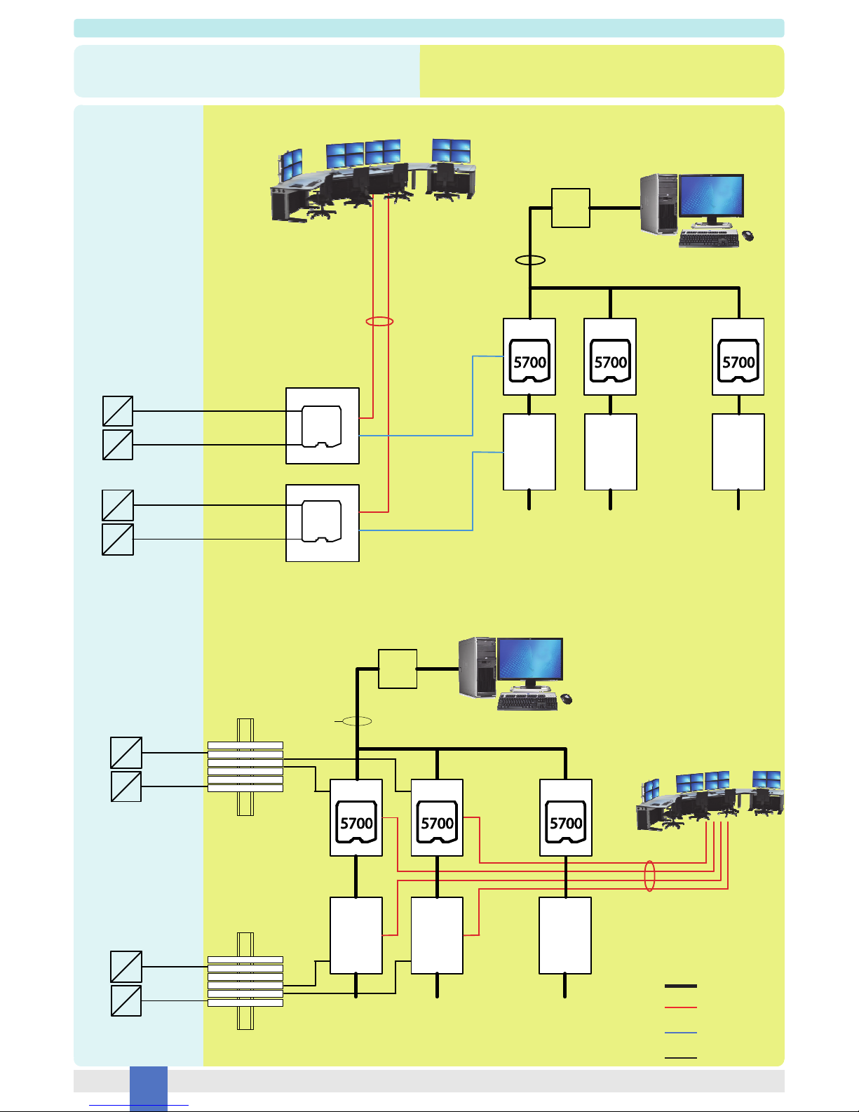
The HART® Multiplexer Modem 5700 interfaces up to 256 smart devices (transmitters, I/P, proportional valves, etc…) in a HART® Network. Each device can be fully identified,
configured and monitored by a remote PC running an FDT-based software package (PACTware™, etc...) through a dedicated Device Type Manager (DTM).
Up to 63 Multiplexer Modem 5700 (16128 loops) can be connected in multi-drop mode to the PC through the RS485 HART® Protocol, whose baudrate can be configured via software.
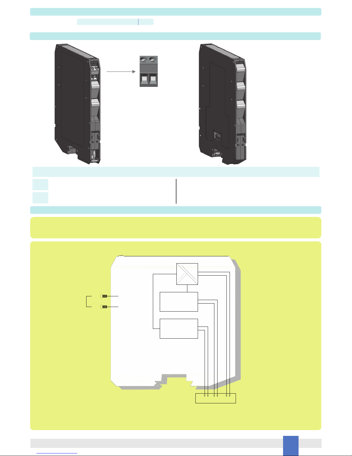
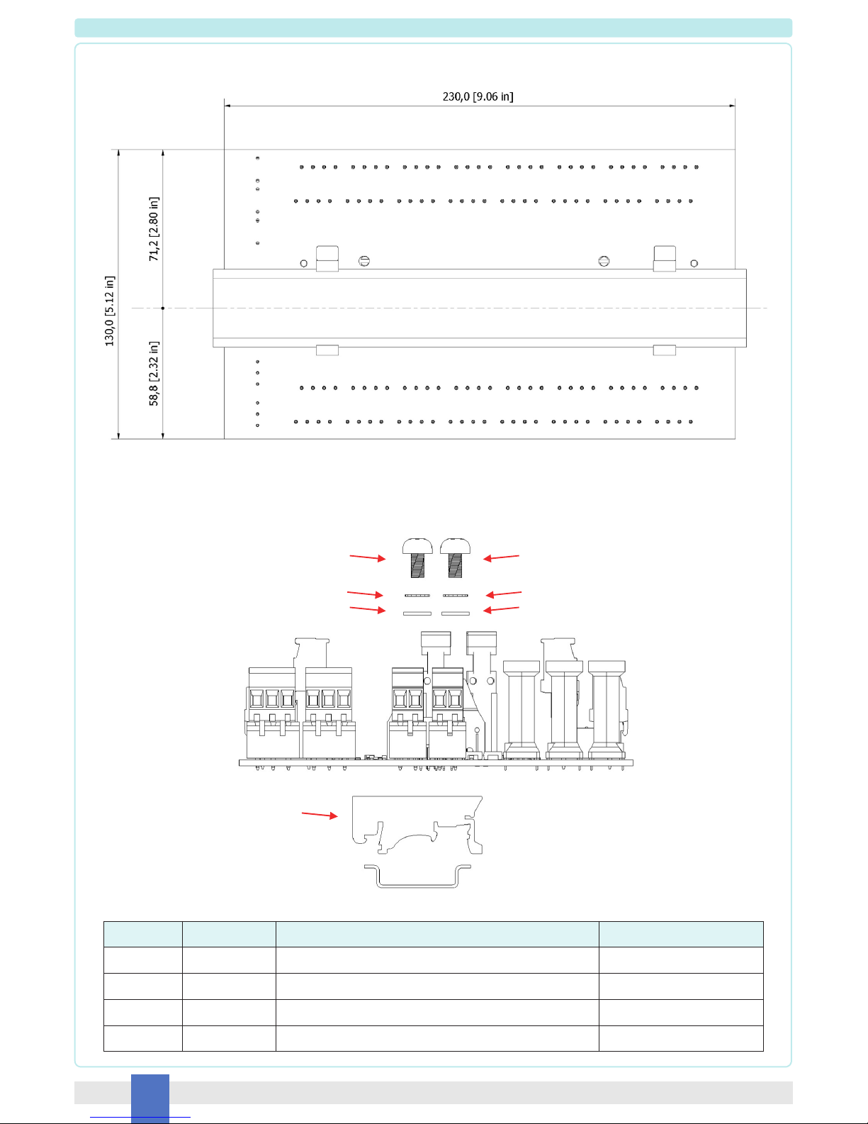
The module is intended to be mounted on the following Termination Boards:
TB-D5001-HRT-003: to be used with G.M. International AI/AO Termination Boards;
TB-D5001-HRT-004: to be used with DIN-Rail mounted barriers/isolators or direct field connections, for 4-20mA loop signal;
TB-D5001-HRT-005: to be used with DIN-Rail mounted barriers/isolators or direct field connections, for 1-5V loop signal.
Termination board types can be combined to manage different interfaces at the same time, simply respecting maximum number of connected channels.
The HART® Multiplexer Modem 5700 is SIL 3 certified as non-interfering with the signal loops.
The module guarantees three-port (supply/interface/channels) isolation.
Functional Safety Management Certification:
G.M. International is certified by TUV to conform to IEC61508:2010 part 1 clauses 5-6 for safety related systems up to and included SIL3.
Technical Data
Characteristics
Supply:
24 Vdc nom (18 to 30 Vdc) reverse polarity protected, via Termination Board.
Current consumption @ 24 V: 40 mA typical (in full topology configuration).
Power dissipation: 0.5 W @ 24 V typical (modem only), 1 W @ 24 V typical (in full topology configuration).
Isolation (Test Voltage):
Interface/Power Supply: 500 Vrms.
Interface/Field channels: 500 Vrms.
Power Supply/ Field channels: 500 Vrms.
Input:
Number of channels: 256.
HART®field device Input: revision 5 to 7.
Interface:
Baudrate: from 1200 to 115200 bps, software configurable.
Address: 0 - 62, software configurable.
Type: RS-485 differential pair and grounding.
Topology: multi-drop, master/slave connection.
Compatibility:
CE mark compliant, conforms to Directives:
2014/34/EU ATEX, 2014/30/EU EMC, 2014/35/EU LVD, 2011/65/EU RoHS.
Environmental conditions:
Operating: temperature limits – 40 to + 70 °C, relative humidity 95 %, up to 55 °C.
Storage: temperature limits – 45 to + 80 °C.
Safety Description:
ATEX: II 3G Ex nA IIC T4 Gc
IECEx : II 3G Ex nA IIC T4 Gc
non-sparking electrical equipment.
Approvals:
ATEX conforms to EN60079-0, EN60079-15 (pending).
IECEx conforms to IEC60079-0, IEC60079-15 (pending).
SIL 3 conforms to IEC61508:2010 Ed. 2 (pending).
TÜV Certificate No. C-IS-236198-09, SIL 3 Functional Safety Certificate conforms to IEC61508:2010 Ed.2, for Management of Functional Safety.
Mounting:
on customized Termination Board.
Weight: about 100 g.
Location: installation in Safe Area or Zone 2, Group IIC T4.
Protection class: IP 20.
Dimensions: Width 12.5 mm, Depth 123 mm, Height 120 mm.
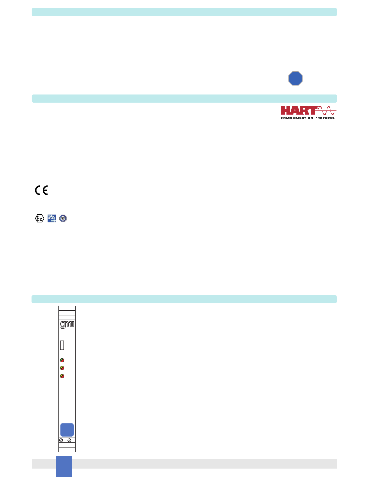
Front Panel and Features
SIL 3 according to IEC 61508:2010 Ed. 2.
Systematic capability SIL 3.
Input from Zone 2, installation in Zone 2.
High Density, 256 Input channels.
HART® field device input, revision 5 to 7.
Three port isolation, Supply/Interface/Channels.
EMC Compatibility to EN61000-6-2, EN61000-6-4, EN61326-1 for safety system.
ATEX, IECEx, TÜV Certifications (pending).
TÜV Functional Safety Certification.
Simplified installation using standard customized Termination Boards.
RS-485 Interface.
FSM
SIL 3
7 8
5700
SIL 3
CONFIG
POWER
COMM.
OPER.

3
5700 - SIL 3 HART®Multiplexer ModemG.M. International ISM0366-2
Ordering Information
Optional short with 8 for write protection
Terminal block connections
SAFE AREA, ZONE 2
Optional short with 7 for write protection
7
8
Model: 5700
7 8
Function Diagram
SAFE AREA, ZONE 2 GROUP IIC T4
MODEL 5700
Termination
board
connector
==
=
Serial
interface
HART
Modem
7
8
optional write
protection

4 5700 - SIL 3 HART®Multiplexer Modem G.M. International ISM0366-2
4/20 mA
signals
AO
AI
...
TB-D5001
-HRT-003
HART Signal
GMITB 2
GMITB 1 12
64 ch.
64 ch.64 ch. 64 ch.
31
RS485
TB-D5001
-HRT-003
64 ch.
TB-D5001
-HRT-003
TB-D5001
-HRT-003
TB-D5001
-HRT-003
TB-D5001
-HRT-003
64 ch.
...
I
P
?
I
I
P
?
I
Barriers
Barriers
...
TB-D5001
-HRT-xxx
DIN-Rail
AI/AO Barriers
DIN-Rail
AI/AO Barriers
12
32 ch.
32 ch.32 ch. 32 ch.
31
RS485
TB-D5001
-HRT-xxx
32 ch.
TB-D5001
-HRT-xxx
TB-D5001
-HRT-xxx
TB-D5001
-HRT-xxx
TB-D5001
-HRT-xxx
32 ch.
..
I
P
?
I
I
P
?
I
Loop Diagrams (IS Applications):
SAFE AREA, ZONE 2 GROUP IIC T4
HAZARDOUS AREA ZONE 0 (ZONE 20) GROUP IIC
RS485 HART®
4/20 mA or 1-5 V
HART®
4/20 mA + HART®
Fig. 1: Barriers on Termination Boards
Fig. 2: Barriers on DIN-Rail
RS485/USB or
Ethernet converter
Workstation PC
running instrument
management software
up to 16128 HART®devices
Up to 63 HART®Mux 5700 modules
Up to 4
TB-D5001-HRT-003
HART®transmitters
and valve positioners
Process control system e.g. DCS,PLC
RS485/USB or
Ethernet converter Workstation PC
running instrument
management software
up to 16128 HART®devices
Process control system e.g. DCS,PLC
Up to 63 HART®Mux 5700 modules
HART®transmitters
and valve positioners
0 1 62
0 1 62
Up to 8
TB-D5001-HRT-xxx
≥004xxx

5
5700 - SIL 3 HART®Multiplexer ModemG.M. International ISM0366-2
...
TB-D5001
-HRT-xxx
DIN-Rail
AI/AO Isolators
12
32 ch.
32 ch.32 ch. 32 ch.
31
RS485
TB-D5001
-HRT-xxx
TB-D5001
-HRT-xxx
TB-D5001
-HRT-xxx
TB-D5001
-HRT-xxx
TB-D5001
-HRT-xxx
..
I
P
?
I
I
P
?
I
32 ch. 32 ch.
4/20 mA
signals
AO
AI
...
TB-D5001
-HRT-003
HART Signal
GMITB 2
GMITB 1 12
64 ch.
64 ch.64 ch. 64 ch.
31
RS485
TB-D5001
-HRT-003
64 ch.
TB-D5001
-HRT-003
64 ch.
...
I
P
?
I
I
P
?
I
Isolators
Isolators
Loop Diagrams (Non-IS Applications):
SAFE AREA, ZONE 2 GROUP IIC T4
Fig. 3: Isolators on Termination Boards
Fig. 4: Isolators on DIN-Rail or Direct Field Connections
RS485/USB or
Ethernet converter
Workstation PC
running instrument
management software
up to 16128 HART®devices
Up to 63 HART®Mux 5700 modules
Up to 4
TB-D5001-HRT-003
Process control system e.g. DCS,PLC
HART®transmitters
and valve positioners
RS485/USB or
Ethernet converter Workstation PC
running instrument
management software
up to 16128 HART®devices
Process control system e.g. DCS,PLC
Up to 63 HART®Mux 5700 modules
HART®transmitters
and valve positioners
RS485 HART®
4/20 mA or 1-5 V
HART®
4/20 mA + HART®
0 1 62
0 1 62
Up to 8
TB-D5001-HRT-xxx
≥004xxx

6 5700 - SIL 3 HART®Multiplexer Modem G.M. International ISM0366-2
DIN-Rail mounting and overall dimensions
All dimensions are expressed in millimeters [inches]
Ref. Nr Q.ty Description Material
1 2 T35 Din Rail Adapter PA
2 4 3.5 x 9.5 Self tapping screw Stainless Steel
3 4 M3 External Tooth loch Washer Stainless Steel
4 4 M3 Washer Stainless Steel
Bottom view
Assembly TB-OPT-001 kit
2
3
4
2
3
4
1

7
5700 - SIL 3 HART®Multiplexer ModemG.M. International ISM0366-2
Mounting and removing Termination Board onto DIN-Rail
Mounting
2.
Removing
Screwdriver
1.
2.
Pull the Termination Board upwards and
remove from DIN-Rail
1.
Push to engage

8 5700 - SIL 3 HART®Multiplexer Modem G.M. International ISM0366-2
Wall mounting and overall dimensions for M4 self tapping screw
Bottom view
Assembly TB-OPT-001 kit
5
6
7
5
6
7
Ref. Nr Q.ty Description Material
5 4 M4 x 8 Screw Stainless Steel
6 4 M4 External Tooth lock Washer Stainless Steel
7 8 M4 Washer Stainless Steel
8 4 Self Tapping Spacer NI - Plated Brass
77
88
All dimensions are expressed in millimeters [inches]

9
5700 - SIL 3 HART®Multiplexer ModemG.M. International ISM0366-2
Wall mounting and overall dimensions for M4 thread screw
Bottom view
Assembly TB-OPT-001 kit
9
10
11
9
10
11
Ref. Nr Q.ty Description Material
9 4 M4 x 8 Screw Stainless Steel
10 8 M4 External Tooth lock Washer Stainless Steel
11 8 M4 Washer Stainless Steel
12 4 Threaded Spacer NI - Plated Brass
13 4 M4 Nut Stainless Steel
1111
1212
1010
1313
All dimensions are expressed in millimeters [inches]

10 5700 - SIL 3 HART®Multiplexer Modem G.M. International ISM0366-2
Mounting the HART®Mux 5700 module onto a Termination Board
Latching
mechanism
1. Push over the module to
Termination Board, aligning
the module to the latching
mechanism.
2. Press bottom up the
latching mechanism.
Removing the HART®Mux 5700 module from Termination Board
1. Unclip the latching
mechanism.
2. Pull up the module from
Termination Board.
Mounting HART®Mux 5700 module onto Termination Board

11
5700 - SIL 3 HART®Multiplexer ModemG.M. International ISM0366-2
The 5700 is an electrical apparatus located in Safe Area or Zone 2, Group IIC, Temperature T4 Hazardous Area (according to EN/IEC60079‐15) within the specified operating tempera-
ture limits Tamb ‐40 to +70 °C.
The 5700 must be installed, operated and maintained only by qualified personnel, in accordance to the relevant national/international installation standards (e.g. EN/IEC60079‐14 Electri-
cal apparatus for explosive gas atmospheres - Part 14: Electrical installations in hazardous areas (other than mines)), following the established installation rules.
De‐energize power source (turn off power supply voltage) before plug or unplug the terminal blocks when installed in Hazardous Area or unless area is known to be nonhazardous.
Warning: substitution of components may impair suitability for Zone 2.
Explosion Hazard: to prevent ignition of flammable or combustible atmospheres, disconnect power before servicing or unless area is known to be nonhazardous.
Failure to properly installation or use of the equipment may risk to damage the unit or severe personal injury.
The unit cannot be repaired by the end user and must be returned to the manufacturer or his authorized representative. Any unauthorized modification must be avoided.
Warning
Installation
The 5700 is a HART®multiplexer modem housed in a plastic enclosure suitable for installation on customized Termination Board.
The 5700 unit can be mounted with any orientation over the entire ambient temperature range.
Electrical connection by polarized plug-in removable screw terminal blocks of conductors up to 2.5 mm² (for Write Protection terminal block) can be plugged in/out into a powered unit
without suffering or causing any damage. The wiring cables have to be proportionate in base to the current and the length of the cable.
Electrical connection to termination board can be plugged in/out into a unit without suffering or causing any damage (for Zone 2 installations check the area to be nonhazardous before
servicing).
Installation and wiring must be in accordance to the relevant national/international installation standards (e.g. EN/IEC60079-14 Electrical apparatus for explosive gas atmospheres - Part
14: Electrical installations in hazardous areas (other than mines)), make sure that conductors are well isolated from each other and do not produce any unintentional connection.
The enclosure provides, according to EN60529, an IP20 minimum degree of mechanical protection (or similar to NEMA Standard 250 type 1) for indoor installation, outdoor installation
requires an additional enclosure with higher degree of protection (i.e. IP54 to IP65 or NEMA type 12-13) consistent with the effective operating environment of the specific installation.
Units must be protected against dirt, dust, extreme mechanical (e.g. vibration, impact and shock) and thermal stress, and casual contacts. If enclosure needs to be cleaned use only a
cloth lightly moistened by a mixture of detergent in water.
Electrostatic Hazard: to avoid electrostatic hazard, the enclosure of 5700 must be cleaned only with a damp or antistatic cloth.
Any penetration of cleaning liquid must be avoided to prevent damage to the unit. Any unauthorized card modification must be avoided.
System topology
The HART®Mux 5700 can be used in five possible connection schemes, depending on the installation requirements and specific applications:
1. Direct connection to the field devices.
2. Connection through isolators installed on a DIN rail.
3. Connection through isolators installed on termination boards.
4. Connection through intrinsically safe barriers installed on a DIN rail.
5. Connection through intrinsically safe barriers installed on termination boards.
Each HART®Mux 5700 can manage a maximum of 256 channels, while the TB-D5001-HRT-003 (flat cables) and the other ones (terminal blocks) connect 64 and 32 channels
respectively. This means that up to 4 TB-D5001-HRT-003 and 8 other type can be cascaded.
Power supply and RS-485 line shall be connected only to the termination board where HART® Mux 5700 is mounted (the first of the chain).
LED indication
The front panel of the HART®Mux 5700 has three LEDs, which indicate the presence of the supply (POWER), the communication to the field (COMM.) and the specific operation
(OPER.) carried out by the multiplexer. An exhaustive explanation is given in Table 1.
Table 1: Meaning of the LEDs.
Three LEDs are available on the termination board. Two green LEDs are dedicated to the independent power supplies, while the yellow one indicates the status of the communication to
the modem.
Operation LED (OPER.) Field LED (COMM.) Power LED (POWER) Condition
OFF OFF OFF No power supply
OFF OFF Green slow flashing USB configuration
OFF OFF Green fast flashing Initial start-up
Yellow slow flashing Yellow intermittent flashing Green Building
OFF OFF Green Power on, idle state
OFF Yellow intermittent flashing Green Field ongoing communication
Yellow fast flashing Yellow intermittent flashing Green Scanning
Red fast flashing Yellow intermittent flashing Green Scanning, one or more loops disap-
peared
Red Red Red Hardware fault
HART®Mux configuration
Before using the HART®Mux 5700, baudrate and polling address must be configured. To carry out the configuration, connect the mini-USB to the PPC5090 adapter without supplying the
unit (the green power led flashes). Start the SWC5090 software (Figure 1). Choose the baudrate for the RS485 bus from the corresponding drop down menu. The polling address should
be a value from 0 to 62, unique within the bus. When the configuration is done, save the information to the device by pressing the “Store to device” button, remove the mini-USB and
mount the HART®Mux 5700 on the termination board.

12 5700 - SIL 3 HART®Multiplexer Modem G.M. International ISM0366-2
Figure 1: SWC5090 configuration software.
Start-up Sequence (Building)
At start-up the HART®Mux 5700 runs a 10s self-test procedure, indicated by the fast flashing of the power (green) LED on the unit and the slow flashing of the Communication (yellow)
LED on the termination board. Once this is over, the two LEDs stop flashing, hence indicating that the board has correctly been addressed by the HART®Mux 5700.
Then the Mux proceeds with the building operation, indicated by the slow flashing of the yellow operation LED: all the available channels are sequentially searched for smart devices to
allow direct communication between the host and the field slaves. The duration of this phase depends on a few variables: the number of connected termination boards, the actual
presence of connected devices, the number of configured retries on error, the configured search mode. The slow flashing of the yellow operation LED lasts until building is over.
Scanning
The scan is a specific operation made available by the HART®Mux 5700 that allows the user to monitor all connected field devices continuously. A selectable HART®command (1, 2 or
3) can be used to scan the slaves. A fast flashing of the yellow operation LED indicates that the scan is active. If one or more devices disappear, the operation LED light turns red. The
updated results of the scan operation are available in the Diagnosis, Boards Diagnosis and Display Values Window (see following sections) of the frame program.
FDT Technology
FDT (Field Device Tool) is an open standard for industrial automation that aims at controlling and monitoring networks of devices over many possible communication protocols, e.g.
HART®.
FDT requires a frame program running on a Host PC that loads the DTM (Device Type Manager) libraries describing the behaviour and the parameters available for each field device.
PACTware™ (Process Automation Configuration Tool) is the recommended frame program, which can be downloaded from several webpages, such as
http://www.icsgmbh.de/en/download-en/pactware-4-1.html, together with the instruction manual. The frame program requires a HART®Communication DTM, which can be found at the
same link.
In order to communicate with the hardware, an RS232/RS485 converter should be connected to the serial port of the Host. The suggested converter is the D1061S by GM International
(http://www.gminternationalsrl.com/index.php?pid=D1061S). The necessary settings are contained in the corresponding instruction manual.
The DTM of the HART®Mux 5700 is available at the GM International website (http://www.gminternationalsrl.com). To install it, download executable file and double click it; then, follow
on screen instructions. The DTM of the field devices should be fetched from the single manufacturers web pages.
The minimum required software tools, to be able to operate the HART®network, are the following:
PACTware™ (4.1 recommended);
HART®Communication DTM;
DTM of HART®Mux 5700;
DTM of connected field devices.

13
5700 - SIL 3 HART®Multiplexer ModemG.M. International ISM0366-2
HART®Mux 5700 FDT Setup
In order to access the HART®Mux 5700 functionalities, it is necessary to setup the frame program, e.g. PACTware™ (Figure 2).
Figure 2: PACTware™.
At the first start up after DTM installation a device catalog update is recommended.
Add the HART®communication DTM to the Host in the Project window on the left (right click on HOST PC, select Add device and pick up the HART®Communication DTM). Choose
“HART®multpliexer” as “Communication interface”. An example of configuration is given in Figure 3. Note that the baudrate should match the HART®Mux 5700 configuration. Note also
that start and end address should include all the desired HART®Mux polling addresses.
Figure 3: HART®Communication DTM configuration.
At this point two options are possible: if the user works online and all the hardware set up is in place, it is sufficient to connect the Communication DTM (right click on the Communication
DTM and select Connect) and to run an automatic scan (right click on the Communication DTM and select Topology Scan). The connection tree is fully searched, HART®Muxes and field
devices should automatically be located and the corresponding DTMs instantiated in the Project window. When more DTMs are possible for a single device, the Topology Scan window
waits for the user to select the desired one.
Alternatively, the user can design his connection tree offline, by adding the devices in turn in the Project window. HART®Muxes should be directly appended to the Communication
DTM, whereas the devices should be added to the specific HART®Mux they belong to, connected to the corresponding channel. Whichever solution the user prefers the final result
should be similar to Figure 4.

14 5700 - SIL 3 HART®Multiplexer Modem G.M. International ISM0366-2
Figure 4: Project example.
Note that each HART®Mux directly connected to the RS485 bus must have an individual address that matches the one specified in the Communication DTM. To change the addresses,
right click on the Communication DTM, select Change DTM address and specify, in case, a new address by picking up the desired HART®Mux in the main window. Communication DTM
must be in “disconnected” state to allow this operation.
Device-Specific Window Access
The main purpose of the HART®Mux 5700 DTM is to give the user the possibility of accessing the DTM of the connected devices. By double clicking on a device in the Project Window,
the corresponding DTM opens and displays all the information and features that the manufacturer made available (Figure 5).
Figure 5: Device-Specific Window Access.
HART®Mux 5700 Specific Windows
The HART®Mux 5700 DTM makes available different specific service windows (highlighted in Figure 6):
1. Parameter: multiplexer parameters.
2. Diagnosis: multiplexer cumulative diagnosis.
3. Additional Functions
a. Service: rebuild functions and other utilities.
b. BoardsDiagnosis: board channel distribution and loop monitor.
c. Display Values: dynamic variables for all loops.
These windows are explained in more details in the following sections.

15
5700 - SIL 3 HART®Multiplexer ModemG.M. International ISM0366-2
Figure 6: HART®Mux 5700 specific windows.
HART®Mux 5700 Parameter Windows
To enter the Parameter Window (Figure 7), right click on the specific HART®Mux 5700 in the Project Window and select Parameter from the context menu.
Figure 7: HART®Mux 5700 Parameter Window.
The parameters are organized in five sections. The asterisks distinguish the read-only data.
Master
Polling Address*: short address for topology search (it must be set through the SWC5090)
Master Type: primary or secondary master type
Scan
Scan Mode: scan switch
Scan Command: HART®command used to scan the devices
Communication
Retries on Busy: number of retries when the device replies busy
Retries on Error: number of retries when the device replies with errors
Search Mode: building only polling address 0 (Channel 0) or from polling address 0 to 15 (All Channels) on each loop. Note that the search mode from 0 to 15 can be much slower.
Message
Message: 32-character message string stored in the device
Device
Tag: 8-character tag string stored in the device
Descriptor: 16-character descriptor string stored in the device
Last configuration day*: day of the last configuration (automatically written by the DTM)
Last configuration month*: month of the last configuration (automatically written by the DTM)
Last configuration year*: year of the last configuration (automatically written by the DTM)
Device Id: device serial number

16 5700 - SIL 3 HART®Multiplexer Modem G.M. International ISM0366-2
Universal Command Revision*: HART®revision supported by the DTM
Software Revision*: firmware release
Hardware Revision*: hardware release
Default Preambles to Devices: default number of preambles sent to the field devices. This default value will be adapted channel by channel after rebuilding.
HART®Mux 5700 Diagnosis Windows
To enter the Diagnosis Window (Figure 8), right click on the HART®Mux 5700 in the Project Window and select Diagnosis from the context menu.
Figure 8: HART®Mux 5700 Diagnosis Window.
When entering the Diagnosis Window, the DTM periodically communicates with the corresponding hardware to report the following information:
1. Loop disappeared: at least one loop has disappeared.
2. Mux in rebuild: the HART®Mux 5700 is busy in rebuilding.
3. Mux in scan: the HART®Mux 5700 is scanning over the active channels.
4. EEPROM error: the built-in non-volatile memory has an unrecoverable failure.
HART®Mux 5700 Boards Diagnosis Windows
To enter the Boards Diagnosis Window (Figure 9), right click on the HART®Mux 5700 in the Project Window and select Additional Functions -> BoardsDiagnosis from the context menu.
Figure 9: HART®Mux 5700 Boards Diagnosis Window.
Note: cumulative screens (BoardsDiagnosis and Display Values) are highly resource consuming for the operating system. Opening one window of each kind at a time is suggested.
On the left the connected termination boards are listed. By clicking on a single board all the information is given about the status of each device connected to it. Note that the data are
periodically updated.
For each loop the following data are displayed:
Loop status: grey means loop not active, green means loop active, red means loop disappeared.
Malfunction: red means device malfunction.

17
5700 - SIL 3 HART®Multiplexer ModemG.M. International ISM0366-2
Conf Changed: yellow means that the device configuration has changed since the last configuration save.
More Status: yellow means that more status information is available for the device.
Curr Fix: yellow means that the current is in fixed mode.
Curr Sat: yellow means that the current is saturated.
Pri Var OOL: yellow means that the primary variable is out of limits.
Non Pri Var OOL: yellow means that a non-primary variable is out of limits.
In case of anomalies on a loop, it is possible to retrieve the specific transmitter from the loop number by right clicking on the HART®Mux 5700 in the Project Window and selecting
Display Channels (Figure 10).
Figure 10: Display Channel on Project Window.
HART®Mux 5700 Service Windows
To enter the Service Window, right click on the HART®Mux 5700 in the Project Window and select Additional Functions -> Service.
Two sections are available in this window, Rebuild (Figure 11) and Utility (Figure 13).
Figure 11: HART®Mux 5700 Service Rebuild Window.
At start-up all loops are rebuilt, i.e. the HART®Mux 5700 browses all channels searching for connected devices and it stores the identity information for each field slave. However, at any
point the user can ask the mux to perform the build operation again, on all or on a single loop.
The HART®Mux 5700 makes available the following services:
Rebuild loops: all loops are rebuilt.
Rebuild single loop number: a single loop in the range 1 to 256 can be rebuilt.
The yellow light indicates that the HART®Mux 5700 is rebuilding.
After any rebuild operation it is recommended to restart the Topology Scan on the specific multiplexer. To do so, right click on the HART®Mux 5700 in the Project Window and select
Topology Scan. On the upcoming window, right click on the root multiplexer, select Mark as not scanned (Figure 12) and run the search. The devices below the multiplexer are visited
anew and the differences in the topology are found.

18 5700 - SIL 3 HART®Multiplexer Modem G.M. International ISM0366-2
Figure 12: Topology Scan on Mux level.
Figure 13: HART®Mux 5700 Service Utility Window.
In the Utility Window the user can reset the device, monitor and reset the configuration changed flag.
HART®Mux 5700 Display Values Windows
To enter the Display Values Window (Figure 14), right click on the HART®Mux 5700 in the Project Window and select Additional Functions -> Display Values from the context menu.

19
5700 - SIL 3 HART®Multiplexer ModemG.M. International ISM0366-2
Figure 14: HART®Mux 5700 Display Values Window.
In this window the loop current, the percent of range, the primary variable value and the primary variable unit of the connected devices are displayed. Note that this window requires that
the HART®Mux 5700 is in scan mode. Depending on the specific scan command, a different subset of variables is available:
1. Command 1: primary variable value and unit.
2. Command 2: primary variable loop current and percent of range.
3. Command 3: primary variable loop current, primary variable value and unit.
Note: cumulative screens (BoardsDiagnosis and Display Values) are highly resource consuming for the operating system. Opening one window of each kind at a time is suggested.
The Device-Specific Status contains status information of the HART®Mux 5700 that can be accessed through the HART®Command 48 (Read Additional Device Status). Table 2
indicates how the data are organized.
Table 2: Device-Specific Status.
The HART®Mux 5700 supports the following HART®device-specific commands.
HART®Mux 5700 Device Specific Status
Byte Number Bit Position Description
0 0 Eeprom error
1 Rebuild in progress
2 Scan in progress
3 Loop disappeared
1-2 Loop number in rebuild
3-4 Total number of supported loops
HART®Mux 5700 Device-Specific Commands Specification

20 5700 - SIL 3 HART®Multiplexer Modem G.M. International ISM0366-2
Table 3: Supported device-specific commands
The enumerative types referenced in the commands are defined in the following tables.
Table 4: Master Type
Table 5: Loop Search Type
Table 6: Scan Status
Table 7: Scan HART®Command
Table 8: Loop Scan Status
Command Description
128 Read Multiplexer Topology
129 Read Device Long Address
130 Read Master type
131 Write Master Type
132 Read Loop Search Type
133 Write Loop Search Type
134 Read Retries Number
135 Write Retries Number
136 Rebuild Single Loop
137 Rebuild All Loops
138 Read Scan Status
139 Write Scan Status
140 Read Scan Command
141 Write Scan Command
142 Read Loop Scan Status
143 Write Loop Scan Status
144 Write Protection Switch
145 Read Cumulative Loop/Device Status
146 Read Cumulative Dynamic Data
150 Read Configuration-Changed Flag
Code Description
0 Secondary Master
1 Primary Master
Code Description
0 Polling Address 0
1 Polling Address 0 to 15
Code Description
0 Scan Disabled
1 Scan Enabled
Code Description
0 Scan HART®Command 1
1 Scan HART®Command 2
2 Scan HART®Command 3
Code Description
0 Loop Scan Enabled
1 Loop Scan Disabled
Table of contents
Popular Modem manuals by other brands

XAVI Technologies Corp.
XAVI Technologies Corp. X8121r user manual

Paradyne
Paradyne StormPort 610 Installation Sheet and Users Guide

Digicel
Digicel DX-250 Setup guide

ZyXEL Communications
ZyXEL Communications Omni 56K quick start guide

Zoom
Zoom 3GM1073 quick start guide

Stevens
Stevens 93950A product manual