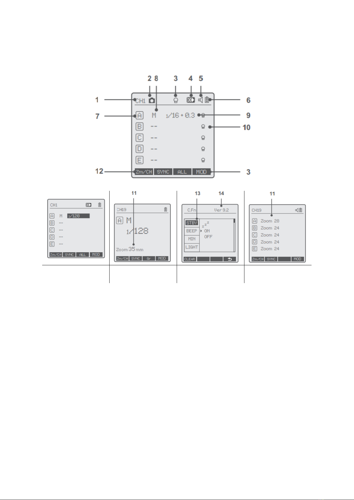
Godox Xpro C User manual

Xpro C
User Manual • Uživatelský manuál •
Užívateľský manuál • Használati utasítás •
Benutzerhandbuch

2
English
3 –25
Čeština
26 –50
Slovenčina
51 –74
Magyar
75 –99
Deutsch
100 –124

3
Dear customer,
Thank you for purchasing our product. Please read the following instructions carefully
before first use and keep this user manual for future reference. Pay particular attention
to the safety instructions. If you have any questions or comments about the device,
please contact the customer line.
✉www.alza.co.uk/kontakt
✆+44 (0)203 514 4411
Importer Alza.cz a.s., Jankovcova 1522/53, Holešovice, 170 00 Prague 7, www.alza.cz

4
Foreword
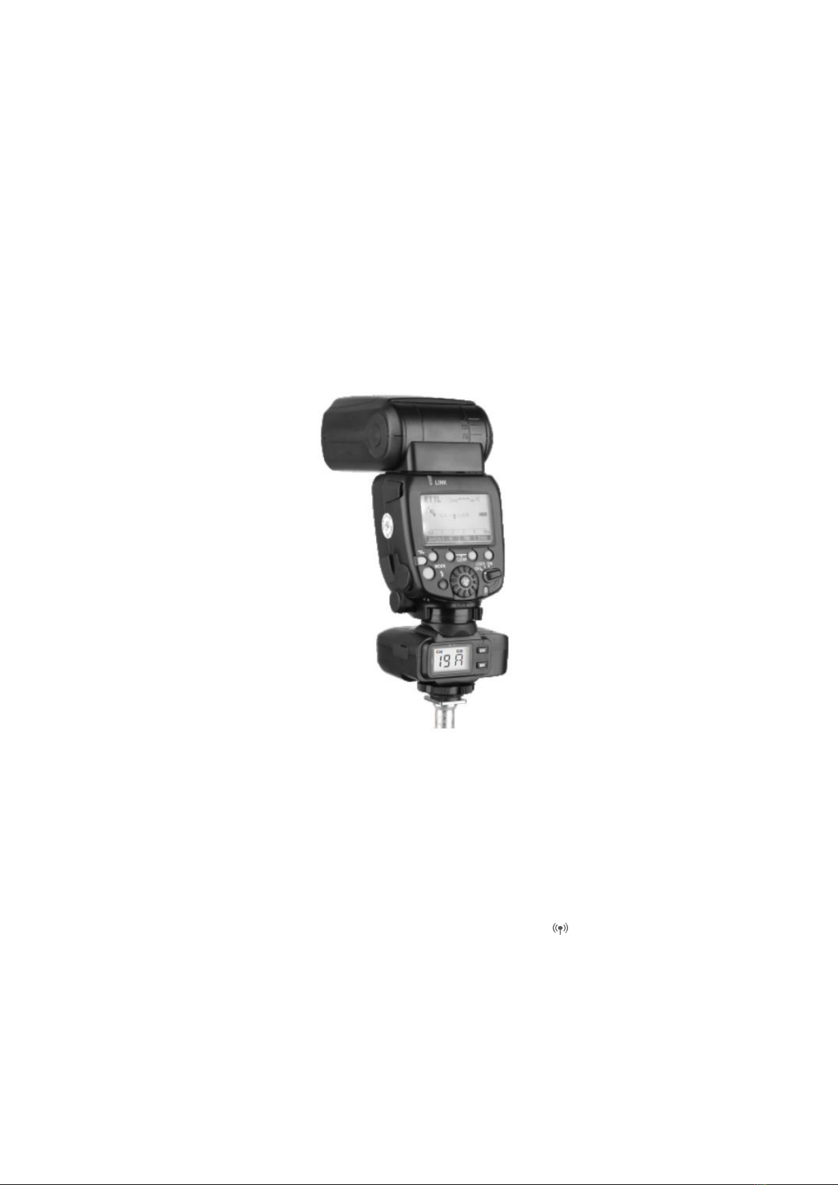
Thanks for your purchase of this XProC wireless flash trigger.
This wireless flash trigger is suitable for using Canon cameras control Godox flashes
with X system e.g. camera flash, outdoor flash, and studio flash. It can also control
Canon original speedlites with the coordination of X1R-C receiver. Featuring multi-
channel triggering, stable signal transmission, and sensitive reaction, it gives
photographers unparalleled flexibility and control over their setups. The flash trigger
applies to hotshoe-mounted Canon EOS series cameras, as well as the cameras which
have PC sync socket.
With XProC wireless flash trigger, high speed synchronization is available for most of
camera flashes in the market which support E-TTL II. The max flash synchronization
speed is up to 1/8000s*.
*: 1/8000s is achievable when the camera has a max camera shutter speed of 1/8000s.
Warning
•Do not disassemble. Should repairs become necessary, this product must be sent
to an authorized maintenance center.
•Always keep this product dry. Do not use in rain or in damp conditions.
•Keep out of reach of children.
•Do not use the flash unit in the presence of flammable gas. In certain
circumstance please pay attention to the relevant warnings.
•Do not leave or store the product if the ambient temperature reads over 50°C.
•Turn off the flash trigger immediately in the event of malfunction.
•Observe precautions when handling batteries.
oUse only batteries listed in this manual. Do not use old and new batteries
or batteries of different types at the same time.
oRead and follow all warnings and instructions provided by the
manufacturer.
oBatteries cannot be short-circuited or disassembled.
oDo not put batteries into a fire or apply direct heat to them.
oDo not attempt to insert batteries upside down or backwards.
oBatteries are prone to leakage when fully discharged. To avoid damage to
the product, be sure to remove batteries when the product is not used for
a long time or when batteries run out of charge.
oShould liquid from the batteries come into contact with skin or clothing,
rinse immediately with fresh water.

5
Name of Parts
Body
LCD Panel
Function Button 3
Function Button 4
MENU Button
Magnification/TCM Button
Status Indicatro Lamp
-- Green: Trigger (Flash)
+ Focus (Camera)
-- Red: Trigger (Flash) +
Shutter (Camera)
Select Dial
TEST/Shutter Button
MODE/LOCK Mode
Selection/Locking Button
Group Button 1
Group Button 2
Group Button 3
Group Button 4
Group Button 5
Function Button 2
Function Button 1
Battery Compartment
Type-C USB Port
2.5mm Sync
Cord Jack
Hot Shoe Camera Connection
AF Assist Beam Switch
-- ON (AF Assist Beam outputs)
-- OFF (AF Assist Beam do not
output)
AF-assist Lamp
Power Switch
-- ON (Power On)
-- OFF (Power Off)

6
LCD Panel
Multi Groups
Display
Single Group
Display
Menu
Multi Groups’
ZOOM Display
1. Channel (32)
2. Camera Connection
3. Modeling Lamp Master Control
4. High-Speed/Rear Curtain Sync
5. Sound
6. Battery Level Indication
7. Group
8. Mode
9. Power
10. Group’s Modeling Lamp
11. ZOOM Value
12. Icons of Function Button
13. C.Fn Menu
14. Version

7
Battery
AA alkaline batteries are recommended.
Installing Batterie
As shown in the illustration, slide the battery compartment lid of the flash trigger and
insert two AA batteries separately.
Battery Indication
Check the battery level indication on the LCD panel to see the remaining battery level
during the usage.
Battery Level Indication
Meaning
3 grids
Full
2 grids
Middle
1 grid
Low
Blank grid
Low battery, please replace it.
Blinking
<2.5V The battery level is going to be used
out immediately (please replace new
batteries, as low power lead to no flash or
flash missing in case of long distance).
The battery indication only refers to AA alkaline batteries. As the voltage of Ni-MH
battery tends to be low, please do not refer to this chart.
Using the Flash Trigger
Ass a Wireless Camera Flash Trigger
Take TT685C as an example:
•Turn off the camera and mount the transmitter on camera hotshoe. Then, power
on the flash trigger and the camera.

8
•Long press the <Zm/CH> button to set channel, group, mode and parameter
(refers to the contents of “Setting the Flash Trigger”).
•Turn on the camera flash, press the < > wireless setting button and the < >
wireless icon and <SLAVE> slave unit icon will be displayed on the LCD panel.
Press the <CH> button to set the same channel to the flash trigger and press the
<Gr> button to set the same group to the flash trigger. (Note: please refer to the
relevant instruction manual when setting the camera flashes of other models).
•Press the camera shutter to trigger and the status lamp of the flash trigger turns
red synchronously.
As a Wireless Outdoor Flash Trigger
Take AD600B as an example.
•Turn off the camera and mount the transmitter on camera hotshoe. Then, power
on the flash trigger and the camera.
•Long press the <Zm/CH> button to set channel, group, mode, and parameters
(refers to the contents of “Setting the Flash Trigger”).
•Power on the outdoor flash and press the < > wireless setting button and the
< > wireless icon will be displayed on the LCD panel. Long press the <GR/CH>
button to set the same channel to the flash trigger, and short press the <GR/CH>
button to set the same group to the flash trigger (Note: please refer to the
relevant instruction manual when setting the outdoor flashes of other models).
•Press the camera shutter to trigger and the status lamp of the flash trigger turns
red synchronously.

9
As a Wireless Original Flash Trigger
Take 600EX-RT as an example:
•Turn off the camera and mount the transmitter on camera hotshoe. Then, power
on the flash trigger and the camera.
•Long press the <Zm/CH> button to set channel, group, mode, and parameters
(refers to the contents of “Setting the Flash Trigger”).
•Attach the original flash to the X1R-C receiver. Press the <CH> button on the
receiver to set the same channel to the flash the trigger and press the <Gr>
button to set the same group to the flash trigger (Note: please refer to the
relevant instruction manual when setting the original camera flashes).
•Press the camera shutter to trigger. And the status lamp of the camera flash and
the flash trigger both turn red synchronously.
As a Wireless Studio Flash Trigger
Take GS400II as an example:
•Turn off the camera and mount the transmitter on camera hotshoe. Then, power
on the flash trigger and the camera.
•Long press the <Zm/Ch> button to set channel, group, mode and parameters
(refers to the contents of “Setting the Flash Trigger”).
•Connect the studio flash to power source and power it on. Synchronously press
down the GR/CH> button and <S1/S2> button and the < > wireless icon will be
displayed on the LCD panel. Long press the <GR/CH> button to set the same
channel to the flash trigger, and short press the <GR/CH> button to set the same
group to the flash trigger. (Note: please refer to the relevant instruction manual
when setting the studio flashes of other models).
•Press the camera shutter to trigger. And the status lamp of the camera flash and
the flash trigger both turn red synchronously.

10
Note: As the studio flash’s minimum output value is 1/32, the output value of the flash
trigger should be set to or over 1/32. As the studio flash do not have TTL and
stroboscopic functions, the flash trigger should be set to M mode in triggering.
As a Wireless Shutter Release Trigger
Operation method:
•Turn off the camera. Take a camera remote cable and insert one end into the
camera’s shutter socket and the other end to the shutter release port of X1R-C to
connect. Power on the camera and the receiver.
•Long press the <Zm/CH> button to set channel, group, mode, and parameters
(refers to the contents of “Setting the Flash Trigger”).
•Press the receiver’s <CH> button to set the same channel to the flash trigger and
press the <Gr> button to set the same group to the flash trigger.
•Half press the < > button to focus and full press the <TEST> button to shoot.
Release the button until the status lamp turns to red.

11
As a Flash Trigger with 2.5mm Sync Cord Jack
Operation method:
•The connection method please refers to the contents of “As a Wireless Studio
Flash Trigger” and “As a Wireless Shutter Release”.
•Press the shutter normally and the flashes will be controlled by sync cord jack’s
signal.
Setting the Flash Trigger
Power Switch
Slide the Power Switch to ON, and the device is on and status indicator lamp will not
reveal.
Note: In order to avoid power consumption, turn off the transmitter when not in use.
Automatically Enter Power Saving Mode
•The system will automatically enter standby mode after stop operating the
transmitter over 90 seconds. And the displays on the LCD panel disappear now.
•Press any button to wake up. If the flash trigger is attached to the host shoe of
CANON EOS camera, half press the camera shutter can also wake the system up.
Note: If do not want to enter power saving mode, press the <MENU> button to enter
C.Fn custom settings and set STBY to OFF.

12
Power Switch of AF Assist Beam
Slide the AF-assist beam switch to ON, and the AF lighting is allowed to output. When the
camera cannot focus, the AF assist beam will turn on, when the camera can focus, the AF
assist beam will turn off.
Channel Setting
•Long press the <Zm/CH> button and the channel value will be chosen.
•Turn the select dial to choose the appropriate channel. Press the <SET> button
again to confirm the setting.
•This flash trigger contains 32 channels which can be changed from 1 to 32. Set
the transmitter and the receiver to the same channel before usage.
Wireless ID Settings
Change the wireless channels and wireless ID to avoid interference for it can only be
triggered after the wireless IDs and channels of the master unit and the slave are set to
the same.
Press the <MENU> button to enter C.Fn ID. Press the <SET> button to choose OFF
channel explosion shutdown, and choose any figure from 01 to 99.
Note: As the current Godox flashes do not have wireless ID setting functions, please set
ID to OFF.
Mode Setting
•Short press the <MODE> button, and the mode of the current group will change.
•Set the groups to five groups (A-E)
oWhen displaying multiple groups, press the <MODE> button to switch the
multi-group mode to MULTI mode. Press the group selection button can
set the MULTI mode to ON or OFF.
oWhen displaying multiple groups, press the group selection button or
<MODE> button in one-group mode, and all the current group’s mode will
be changed by the order to TTL/M/--
•When setting the group to 16 groups (0-F), there is only manual mode M.
•Long press the <MODE> button for 2 seconds until “LOCKED” is displayed on the
button of the LCD panel, which means the screen is locked and no parameters
can be set. Long press the <MODE> button again to unlock.

13
Magnification Function
Switch between multi-group and one-group mode: choose a group in multi-group mode
and press the <TCM> button to magnify it to one-group mode. Then, press the <TCM>
button to back to multi-group.
Output Value Settings
Multi-group displays in the M mode
•Press the group button to choose the group, turn the select dial, and the power
output value will change from Min to 1/1 in 0.3 stop increments. Press the <SET>
button to confirm the setting.
•Press <ALL> button to choose all group’s power output value, turn the select dial,
and all groups power output value will change from Min to 1/1 in 0.3 or 0.1 stop
increments. Press <ALL> button again to confirm the setting.
One-group displays in the M mode
•Turn the select dial and the group’s power output value will change from
Min to 1/1 in 0.3 or 0.1 stop increments.
Note: Min. refers to the minimum value that can be set in M or Multi mode. The
minimum value can be set to 1/128, 1/128 (0.1), 1/256 or 1/256(0.1) according to C.Fn-
STEP. For most of camera flashes, the minimum output value is 1/128 or 1/128 (0.1) and
cannot be set to 1/256 or 1/256(0.1). However, the value can change to 1/256 or
1/256(0.1) when using in combination with Godox strong power flashes e.g., AD600Pro,
etc.

14
Flash Exposure Compensation Settings
Multi-group displays in the TTL mode
•Press the group button to choose the group, turn the select dial, and the
FEC value will change from -3 to ~3 in 0.3 stop increments. Press the
<SET> button to confirm the setting.
•Press <ALL> button to choose all groups ‘FEC value, turn the select dial,
and all group’s FEC value will change from -3 to ~3 in 0.3 stop increments.
Press <ALL> button again to confirm the setting.
One-group displays in the TTL mode
Turn the select dial and the group’s power output value will change from -3 to ~3 in 0.3
stop increments.
Multi Flash Settings (Output Value, Times, and Frequency)
•In the flash (TTL and M icon are not displayed)
•The three lines are separately displayed as power output value, Times
(flash times) and Hz (flash frequency)
•Turn the Select Dial to change the power output value from Min. to 1/4 in
integer stops.
•Short press the Times button can change flash times. Turn the select dial
to change the setting value.
•Short press the Hz button can change flash frequency. Turn the select dial
to change the setting value.
•Until all the amounts are set. Or during any value setting, short press the
<MODE> button to exit the setting status. No values will blink.
•In the multi flash setting submenu, short press the <MODE> button to
return to main menu when no values are blinking.
Note: As flash times are restricted by flash output value and flash frequency, the flash
times cannot surpass the upper value the permitted by the system. The times that
transported to the receiver and are a real flash time, which is also related to the
camera’s shutter setting.

15
Modeling Lamp Settings
•When displaying multiple groups, press the <MOD> button to control the
ON/OFF of the modeling lamp.
•Press the group button to choose the group when displaying multiple
groups or when displaying one-group, press the <MOD> button to control
the ON/OFF of the modeling lamp (note: The models can use one-group to
ON/OFF the modeling lamp are as follows: GSII, SKII, QSII, DEII, DPII series,
etc. The outdoor flash AD200 and AD600 can use this function after
upgrade. The new arrivals with modeling lamps can also use this function.)
ZOOM Value Settings
Short press the <Zm/CH> button and the ZOOM value will be displayed on the LCD
panel. Choose the group and turn the select dial, and the ZOOM value will change from
AUTO/24 to 200. Choose the desired value and long press the <Zm/CH> button again to
back to the main menu.
Note: The flash’s ZOOM should be set to Auto (A) mode before responding.
Shutter Sync Settings
•High-speed sync: press the SYNC button and is displayed on the LCD panel.
•Second-curtain sync: press the <SYNC> button and is displayed on the LCD
panel.

16
Buzz Settings
Press the <MENU> button to enter C.Fn BEEP and press the <SET> button. Choose ON to
turn on the BEEP while OFF to run off it. Press the <MENU> button again to back to the
main menu.
Sync Socket Settings
•Press the <MENU> button to enter C.Fn SYNC and press the <SET> button to
choose IN or OUT. Press the <MENU> button again to back to the main menu.
oWhen choosing IN, this sync socket will enable XProC trigger flash.
oWhen choosing OUT, this sync socket will send trigger signals to trigger
other remote control and flash.

17
TCM Function
TCM transform function is a particular function that owned by Godox:
TTL Flash value transform into power output value in M mode.
•Set the flash trigger to TTL mode and attach it to the camera. Press the shutter
for shooting.
•Long press the <TCM> button, and the flash value in TTL mode will transform into
power output value in M mode (The displayed minimum value is the set Min.
value).
•Please refer to the C.Fn setting custom functions to see the flash models which
are compatible with TCM functions.
Note: Please choose the relevant models in TCM function in C.Fn custom settings
according to your own flash.
SHOOT Function Settings
Press the <MENU> button to enter C.Fn SHOOT. Press the <SET> button to choose one-
shoot or multi-shoots and press the <MENU> button again to back to the main menu.
One-shoot: When shooting, choose one-shoot. In the M and Multi-mode, the master
unit only sends triggering signal to the slave unit, which is suitable for one person
photography for the advantage of power saving.
Multi-shoots: When shooting, choose multi-shoots, and the master unit will send
parameters and triggering signals to the slave unit, which is suitable for multi person
photography. However, this function consumes power quickly.
APP: Only send triggering signal when camera is shooting (control the flash’s
parameters by smartphone APP)

18
C.Fn: Setting Custom Functions
The following table lists the available and unavailable custom functions of this flash.
Custom
Function
Function
Setting Signs
Settings and Description
STBY
Sleep
ON
ON
OFF
OFF
BEEP
Beeper
ON
ON
OFF
OFF
STEP
Power output
value
1/128
The minimum output is 1/128 (change in 0.3
step)
1/256
The minimum output is 1/256 (change in 0.3
step)
1/128(0.1)
The minimum output is 1/128 (change in 0.1
step)
1/256(0.1)
The minimum output is 1/256 (change in 0.1
step)
LIGHT
Backlighting
time
12 sec
Off in 12 seconds
OFF
Always off
ON
Always lighting
SYNC
Sync cord jack
IN
Enable XProC to trigger flash
OUT
Export triggering signal to trigger other remote
control and flash
GROUP
Group
5 (A-E)
5 groups (A-E)
16 (O-F)
16 groups (0-F); 16 groups when the receiver
end is studio flash, which can only be set to M
mode in this state.
LCD
Contrast ratio
of LCD panel
-3-+3
The contrast ratio can be set as integral
number from -3 to +3
SHOOT
One-shoot
Only send triggering signals in the M & Multi
mode when camera is shooting
Full-shoot
Send parameters and triggering signal when
camera is shooting (suitable for multiple person
photography)
APP
APP
Only send triggering signal when camera is
shooting (control the flash’s parameters by
smartphone APP)
DIST
Triggering
distance
0-30m
0-30m triggering
1-100m
1-100m triggering
ID
Wireless ID
OFF
Off
01-99
Choose any figure from 01-99 (the current
version flashes cannot use this function
temporarily)
TCM
TCM Transform
function
TT685/V860II series
The power output
values in the M mode
which are transformed
from TTL mode, begin
subjected to the master
flash when mixing.
200j
AD200
360j
600j
AD360II
AD600

19
Compatible Flash Models
Transmitter
Receiver
Flash
Note
XProC
--
AD600 series/AD360II series
AD200 series/V860II series
V/850II
TT685 series/TT600/TT350C
QuickerII series/QTII/SK II
series
DP II series/GSII
X1R-C
600EX-
RT/580EXII/580EX/430EXII
V860C
As there are so many camera
flashes in the market which
are compatible with Canon
speedlites, we do not test one
by one.
XTR-16
AD360/AR400
The flashes with Godox
wireless USB port
Quicker series/SK series/DP
series
GT/GS series/Smart flash
series
Can only be triggered
XTR-16S
V860C
V850
Note: The range of support functions: the functions that are both owned by XProC and
flash.
The relationship of XT wireless system and X1 wireless system:
XT-16
(Code
Switch)
X1
(Display
Screen)
CH01
CH02
CH03
CH04
CH05
CH06
CH07
CH08
XT-16
(Code
Switch)
X1
(Display
Screen)
CH09
CH10
CH11
CH12
CH13
CH14
CH15
CH16

20
Compatible Camera Models
This flash trigger can be used on the following Canon EOS series camera models:
•This table only lists the tested camera models, not all Canon EOS series cameras.
For the compatibility of other camera models, a self-test is recommended.
•Right to modify this table are retained.
•The cameras which are released before 2012 do not have TTL mode in their D
and E group.
Technical Data
Model
XProC
Compatible cameras
Canon EOS cameras (E-TTL II autoflash)
Support for the cameras that have PC
sync socket.
Power supply
2*AA batteries
Flash Exposure Control
TTL autoflash
E-TTL II
Manual flash
Yes
Stroboscopic flash
Yes
Function
High-speed sync
Yes
Flash exposure compensation
Yes, ±3 stops in 1/3 stop increments
Flash exposure lock
Yes
Focus assist
Yes
Modeling lamp
Control the modeling lamp by the flash
trigger
Beeper
Control the beeper by the flash trigger.
Wireless shutter
The receiver end can control the camera
shooting through the 2.5mm sync cord
jack
ZOOM setting
Adjust the ZOOM value by the transmitter
Firmware upgrade
Upgrade through the Type-C USB port
Memory function
Settings will be stored 2 seconds after last
operation and recover after a restart.
Table of contents
Languages:
Other Godox Recording Equipment manuals