Table of
Contents
1. Product
Introduction.....................................................................................................................................................................................................................................5
1.1 Product overview .................................................................................................................................................................................................................................5
1.2 Main functions .....................................................................................................................................................................................................................................5
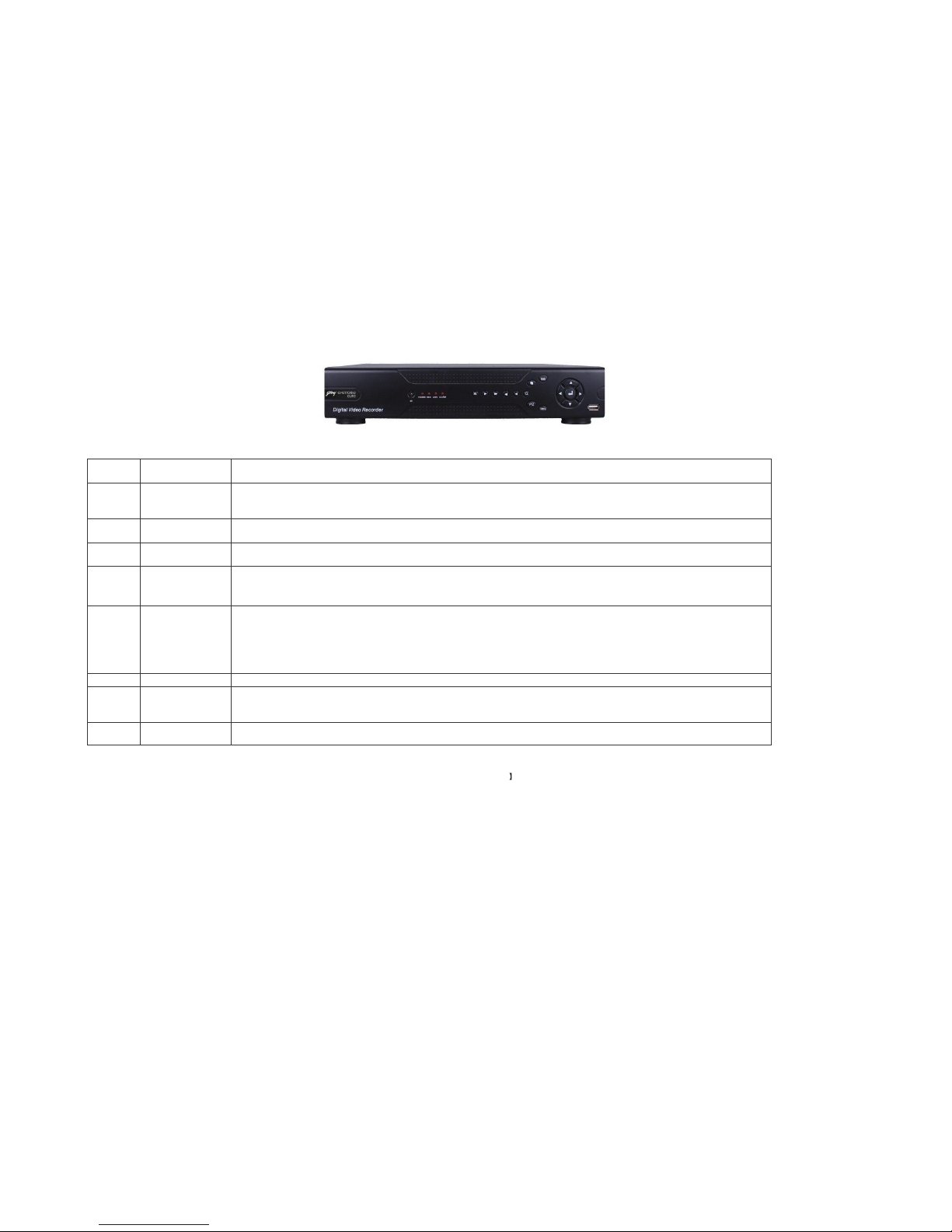
2.1 Description of front panel:....................................................................................................................................................................................................................6
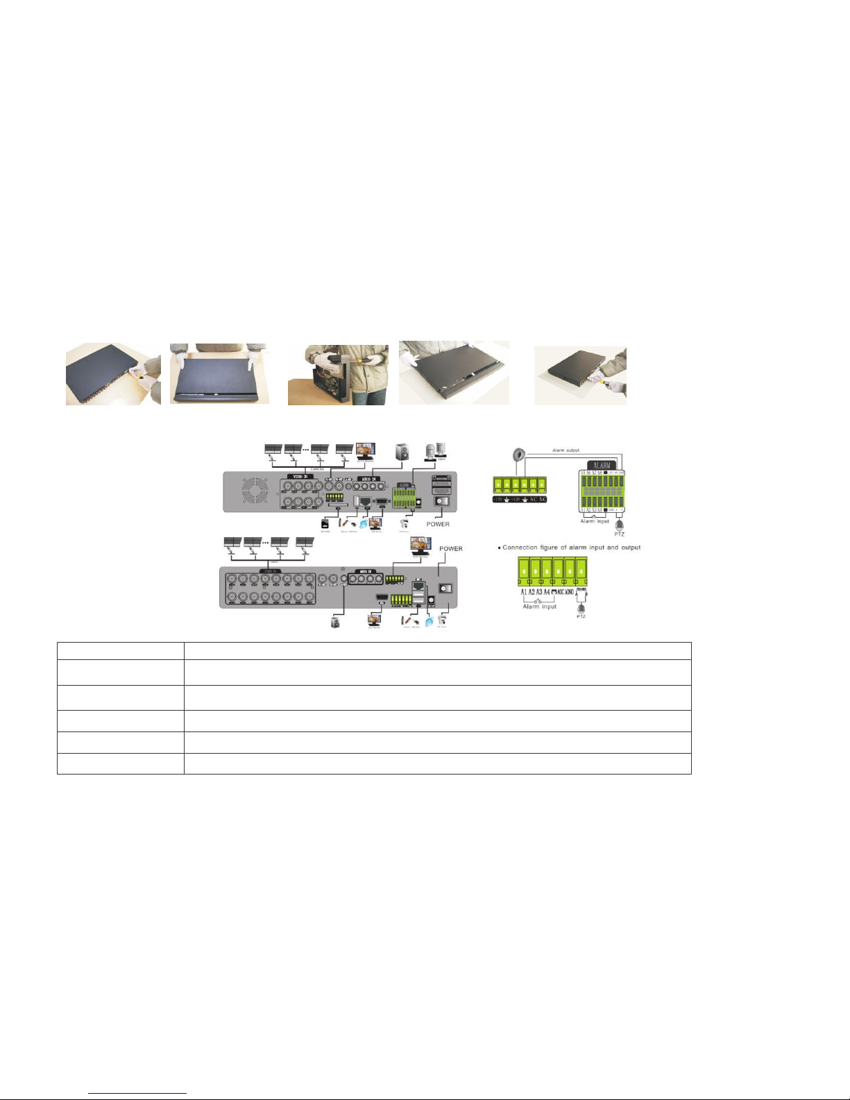
2.2 Hard Disk Installation..........................................................................................................................................................................................................................7
3. Basic
operation.............................................................................................................................................................................................................................................9
3.1 Turn on................................................................................................................................................................................................................................................9
3.2 Turn off...............................................................................................................................................................................................................................................9
3.3
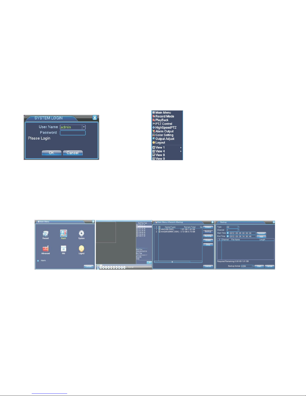
Login
...................................................................................................................................................................................................................................................9
3.4
Preview..............................................................................................................................................................................................................................................
10
3.5 Desktop shortcut menu
......................................................................................................................................................................................................................
10
3.5.1 Main
menu ................................................................................................................................................................................................................................
10
3.5.2 Video playback
.........................................................................................................................................................................................................................
11
3.5.3 Record
Mode.............................................................................................................................................................................................................................
12
3.5.4 Alarm
output .............................................................................................................................................................................................................................
13
3.5.5 PTZ
control
...............................................................................................................................................................................................................................
13
3.5.6 Color
Settings............................................................................................................................................................................................................................
16
3.5.7 TV adjust
..................................................................................................................................................................................................................................
16
3.5.8
Logout.......................................................................................................................................................................................................................................
16
4. Main
Menu.................................................................................................................................................................................................................................................
17
4.1 Main menu
navigation......................................................................................................................................................................................................................
17
4.2 Recording
function
.............................................................................................................................................................................................................................
18
4.2.1 Recording
Configuration.
.........................................................................................................................................................................................................
18
4.2.2 Video playback
.........................................................................................................................................................................................................................
19
4.2.3 Video backup
............................................................................................................................................................................................................................
19
4.3 Alarm
Function ..................................................................................................................................................................................................................................
20
4.3.1 Motion Detect
...........................................................................................................................................................................................................................
20
4.3.2 Video
Blind
...............................................................................................................................................................................................................................
21
4.3.3 Video
Loss ................................................................................................................................................................................................................................
21
4.3.4 Alarm
input
...............................................................................................................................................................................................................................
22
4.3.5 Alarm
output .............................................................................................................................................................................................................................
22
4.3.6
Abnormality
..............................................................................................................................................................................................................................
22
4.4 System setup
......................................................................................................................................................................................................................................
22
4.4.1 General setup
............................................................................................................................................................................................................................
22