manuals.online logo
Brands
  1. Home
  2. •
  3. Brands
  4. •
  5. Goiot
  6. •
  7. Industrial Equipment
  8. •
  9. Goiot SLIM 6 User manual

Goiot SLIM 6 User manual

Notice de montage panneaux SLIM
6
Installation instructions SLIM 6
hatches
MONTAGE INSTALLATION
Le panneau doit être installé sur une surface plane
d’une tolérance maximum de +/- 1mm.
1) Marquer le pont aux cotes de découpe préconisées,
ainsi que l’emplacement des goujons de fixation
(gabarits de découpe disponibles sur commande).
2) Percer un trou dans le pont pour la scie sauteuse, puis
procéder à la découpe complète.
3) Vérifier que le panneau se pose correctement dans
l’emplacement.
4) Réaliser le collage avec un produit adapté en veillant à
la préconisation du collage sur peinture (dépolissage
conseillé pour un collage avec un silicone type SIKA).
Attention, le panneau doit impérativement être fixé
en position fermé sur le pont.
5) Insérer le panneau dans son emplacement et procéder
à la mise en place des écrous sous le pont. Exercer un
couple se serrage de 3Nm maximum. Commencer par les
angles et finir par le milieu des panneaux.
IMPORTANT : Le panneau SLIM 6 est conçu pour être
fixé au pont par collage. La présence des goujons a pour
unique but d’assurer la mise sous pression du panneau
pendant la durée de séchage du produit de collage. Les
goujons n’ont pas de rôle structurel sur la fixation du
panneau.
The hatch must be installed on a flat surface with a
maximum of tolerance of +/- 1mm.
1) Mark the deck with the hatch cut-out dimensions
recommended, and also indicate the location of the
mounting holes (cutting templates available on order).
2) Drill a hole on the deck for the jigsaw, and proceed to
the complete cutting.
3) Check that the hatch fits properly into the allowed
space.
4) Make the bonding with a suitable product, taking care
of sanding lightly the paint on the bonding areas
(recommended for a bonding with silicone type SIKA).
Warning : the hatch must be fixed in closed position
on the deck.
5) Insert the hatch in its location and install the nuts under
the bridge. Exercise a tightening torque of 3Nm
maximum. Start at the corners and finish at the middle of
the hatch.
IMPORTANT: The SLIM 6 hatch is designed to be fixed
to the deck by gluing. The presence of the studs has the
sole purpose of ensuring the pressurization of the panel
during the drying time of the gluing product. The studs
have no structural role on the fixing of the panel.
.
ENTRETIEN MAINTENANCE
• Après chaque sortie en mer, il est recommandé de
rincer les panneaux et de nettoyer les joints à l’eau douce.
N’utilisez jamais de solvants sur la glace pour le
nettoyage au risque de l’endommager.
•La couche de peinture possède une grande dureté qui
protège l’aluminium de l’action des abrasifs légers.
L’entretien courant se fait à l’eau et au détergeant doux,
et par un rinçage à l’eau claire.
• Si la glace est endommagée, elle peut être remplacée.
Identifiez sa référence grâce au tableau ci-dessous. Un
kit de collage accompagné d’une notice explicative est
également disponible. Adressez-vous à un revendeur
GOIOT.
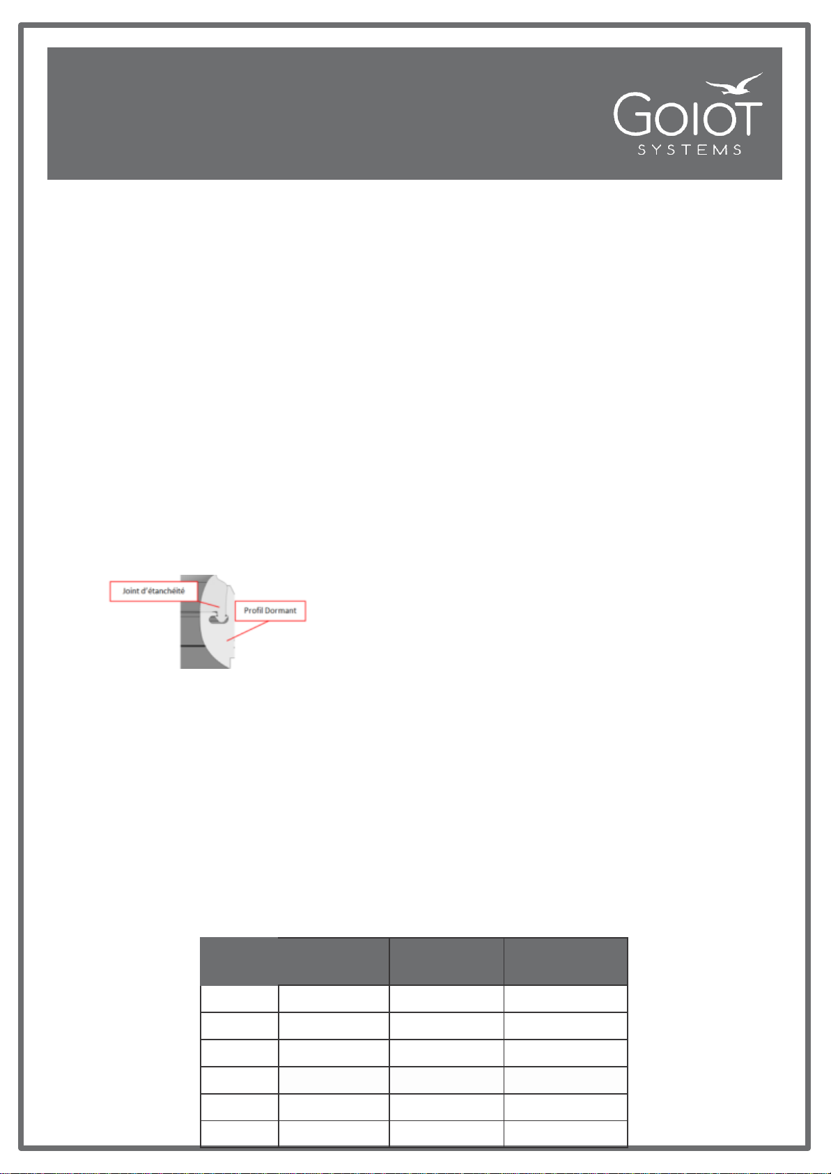
• Le joint d’étanchéité présent sur le dormant est cliplé
dans une gorge comme le montre le schéma ci-dessous.
Il est vivement conseillé de ne pas solliciter le joint par
frottement (passage de voile, passage d’homme par le
panneau, etc..) au risque de décliper ce dernier de son
logement. Si tel est le cas, il suffit de le recliper en
exerçant une pression sur le sommet de la lèvre du joint,
en s’assurant que le sommet de la lèvre du joint soit
rectiligne.
•Pour augmenter la durée de vie du joint d’étanchéité
noir, il est conseillé de le graisser régulièrement an avec
une graisse ou un spray silicone. Au besoin, ce joint peut
également se remplacer (référence des joints dans le
tableau ci-dessous –cf. procédure de changement de
joint).
• After each navigation, it is recommended to rinse the
hatches and seals with fresh water. Never use solvents
for cleaning the acrylics, otherwise they may be damaged.
• The paint layer has a high hardness that protects the
aluminum from the action of light abrasives. Routine
maintenance is done with water and mild detergent, and
by rinsing with clean water.
• If the acrylic is dammaged, it can be replaced. Identify
the hatch model using the chart below and contact your
nearest GOIOT’s distributor (see www.goiot-
systems.com). A glueing kit with refitting instructions is
also available.
• The seal is clipped on the frame into a groove as shown
in the diagram.
It is strongly advised not to solicit the seal by friction
(passage of seals, passage of man by the hatch, etc ..)
with un-clip the seal. If this occurs, the seal can be re-
reclipsed by exerting pressure on the top of the lip of the
seal, making sure that the top of the lip of the seal is
straight.
• To increase the service life of the black seal, it is
advised to oil it regularly with a sillicone grease or spray.
If necessary, this seal can also be replaced (reference of
the joints in the table below - see the procedure for
changing the seal).
Taille
Size
Ref
joint
Seal
ref
Ref compas
Compassref
Ref glace
Acrylic
ref
T10
120610
120970
120570
T30
120611
120971
120571
T44
120576
106970
120572
T54
120861
120973
120573
T60
120612
120973
120574
T70
120613
120972
120575
CHANGEMENT DU JOINT
1) Retirer délicatement le joint défectueux, pour ainsi enlever un maximum de pollution et
résidu de colle dans la gorge. La gorge doit être exempte de toute pollution. Si ce n’est
pas le cas, la nettoyer avec un nettoyant type ALCOOL ISOPROPYLIQUE.
2) Une fois le joint retiré complètement et la gorge propre, le cadre est prêt pour recevoir le nouveau joint.
3) Déposer un cordon continu de silicone sika (ref GOIOT : 121056) dans l’intégralité de la gorge,
à l’exception de l’arrière des charnières.
4) Positionner le joint autour du dormant, en le glissant sous l’ouvrant du panneau. Pour
faciliter cette opération, fermer l’ouvrant à 45°pour faire passer le joint en dessous et le
positionner au-dessus de la gorge du dormant
5) Appuyer sur la base du joint (voir flèche jaune sur schéma) avec les doits pour l’enclencher le pied
dans la gorge, bien insister dans les coins.
6) Terminer par enclencher le joint derrière les charnières à l’aide d’une tige Ø6 environ sans bout pointu
ni arêtes vive, exemple avec une clef Allen.
7) Vérifier que le sommet de la lèvre du joint est parfaitement continu. Une « bosse » ou une « vague »
signifie que le pied du joint est mal inséré à cet endroit. Voir ci-dessous :
Cadre vert : Le sommet de la lèvre du joint est rectiligne.
Cadre Rouge : Nous observons une « vague ». Le joint est mal inséré à cet endroit.
SEAL REPLACEMENT PROCEDURE
1) Carefully remove the faulty seal, for removing a maximum of pollution and glue
residue in the groove. The groove must be free of any pollution. If it is not the
case, clean it with a cleanser type ISOPROPYL ALCOHOL.
2) Once the seal is completely removed and the groove is clean, the frame is ready to receive the new
seal
3) Place a continuous bead of Sika silicone (ref GOIOT: 121056) in the entire groove, except for the
back of the hinges
4) Place the seal around the frame, sliding it under the lid of the hatch. To facilitate
this operation, close the opening at 45 ° to pass the seal underneath and place
it above the groove.
5) Press on the seal base (see yellow arrow on diagram) with the fingers to
engage the foot in the groove, insist on the hatch corners.
6) Finish by snapping the seal behind the hinges with a Ø6 rod or equivalent without pointed end or sharp
Edges (for example with an Allen key).
7) Check that the top of the seal lip is perfectly continuous. A "wave" means that the foot of the seal is not
correctly inserted. See below :
Green frame: the top of the lip of the joint is rectilinear.
Red Frame: we observe a "wave". the seal is improperly inserted here

Popular Industrial Equipment manuals by other brands

ABB TPR56-F32 Operation manual

ABB

ABB TPR56-F32 Operation manual

Virutex UC317S operating instructions

Virutex

Virutex UC317S operating instructions

PCB Piezotronics IMI SENSORS 607A11 Installation and operating manual

PCB Piezotronics

PCB Piezotronics IMI SENSORS 607A11 Installation and operating manual

Montabert V1200 instruction manual

Montabert

Montabert V1200 instruction manual

Dando TERRIER Mk 1 Operating and maintenance manual

Dando

Dando TERRIER Mk 1 Operating and maintenance manual

Kongskilde CUB 1620 manual

Kongskilde

Kongskilde CUB 1620 manual

Repar2 MOSLYSMDS instruction manual

Repar2

Repar2 MOSLYSMDS instruction manual

Woodward GS16 Installation

Woodward

Woodward GS16 Installation

Orbitalum GF 4 Translation of Original Operating Instructions and Spare Parts List

Orbitalum

Orbitalum GF 4 Translation of Original Operating Instructions and Spare Parts List

Power Team PH553C-E220 operating instructions

Power Team

Power Team PH553C-E220 operating instructions

Lissmac SBM-L 1000 G1S2 operating manual

Lissmac

Lissmac SBM-L 1000 G1S2 operating manual

Siemens Power M12 Plug PRO Compact operating instructions

Siemens

Siemens Power M12 Plug PRO Compact operating instructions

Terex Genie SHOV50014B-1001 Operator's manual

Terex

Terex Genie SHOV50014B-1001 Operator's manual

Nabtesco Neco-25 quick start guide

Nabtesco

Nabtesco Neco-25 quick start guide

PISCO VNP Series manual

PISCO

PISCO VNP Series manual

Rapid 110 HL 50/2 Operation manual

Rapid

Rapid 110 HL 50/2 Operation manual

Siemens SIVACON S4 manual

Siemens

Siemens SIVACON S4 manual

Dr.X Works G1-ISOK product manual

Dr.X Works

Dr.X Works G1-ISOK product manual

manuals.online logo
manuals.online logoBrands
  • About & Mission
  • Contact us
  • Privacy Policy
  • Terms and Conditions

Copyright 2025 Manuals.Online. All Rights Reserved.