GOK F-Stop GWG-PG 1 User manual

Originalanleitung / Artikel-Nr. 15 097 50d Ausgabe 07.2015 / Ersatz für Ausgabe 01.2015
Montage- und Bedienungsanleitung
Grenzwertgeber-Prüfgerät Typ F-Stop®GWG-PG 1
für die Funktionsprüfung der Sicherheitseinrichtungen Grenzwertgeber und
Grenzwertgeber mit Füllstandsbegrenzer(n)
INHALTSVERZEICHNIS
ZU DIESER ANLEITUNG......................................................................................................................... 2
ÄNDERUNGEN ZUR VORHERGEHENDEN AUSGABE.......................................................................... 2
PRODUKTBEZOGENE SICHERHEITSHINWEISE.................................................................................. 2
ALLGEMEINE PRODUKTINFORMATION ............................................................................................... 2
BESTIMMUNGSGEMÄSSE VERWENDUNG .......................................................................................... 2
AUFBAU .................................................................................................................................................. 3
VORTEILE UND AUSSTATTUNG............................................................................................................ 3
INBETRIEBNAHME ................................................................................................................................. 3
FUNKTIONSBESCHREIBUNG................................................................................................................ 4
BEDIENUNG............................................................................................................................................ 5
FEHLERBEHEBUNG............................................................................................................................... 5
WARTUNG .............................................................................................................................................. 6
INSTANDSETZUNG ................................................................................................................................ 6
ENTSORGEN .......................................................................................................................................... 6
TECHNISCHE DATEN............................................................................................................................. 6
LISTE DER ZUBEHÖRTEILE................................................................................................................... 6
GEWÄHRLEISTUNG............................................................................................................................... 6
TECHNISCHE ÄNDERUNGEN................................................................................................................ 6
KONFORMITÄTSERKLÄRUNG F-STOP PG-1–EMV–ROHS–DE–2014-09-15 ....................................... 7
NOTIZEN................................................................................................................................................. 8

Grenzwertgeber-Prüfgerät Typ F-Stop®GWG-PG 1
2 / 8 Artikel-Nr. 15 097 50d
ZU DIESER ANLEITUNG
•Diese Anleitung ist ein Teil des Produktes.
•Für den bestimmungsgemäßen Betrieb und zur Einhaltung der Gewährleistung
ist diese Anleitung zu beachten und dem Betreiber auszuhändigen.
•Während der gesamten Benutzung aufbewahren.
•Zusätzlich zu dieser Anleitung sind die nationalen Vorschriften, Gesetze und
Installationsrichtlinien zu beachten.
ÄNDERUNGEN ZUR VORHERGEHENDEN AUSGABE
•EG-Konformitätserklärung aktualisiert
PRODUKTBEZOGENE SICHERHEITSHINWEISE
Auslaufende, flüssige Brenn- und Kraftstoffe wie Heizöl!
•sind gewässergefährdend
•sind entzündbare Flüssigkeiten
•können sich entzünden und Verbrennungen verursachen
•können zu Sturz-Verletzungen durch Ausrutschen führen
Brenn- und Kraftstoffe bei Wartungsarbeiten auffangen!
Verwendung in explosionsgefährdenden Bereichen nicht zulässig!
Kann zu Explosion oder schweren Verletzungen führen.
Einbau vom Fachbetrieb gemäß Betriebssicherheitsverordnung!
Einbau außerhalb der festgelegten Ex-Zone!
ALLGEMEINE PRODUKTINFORMATION
Das Grenzwertgeber-Prüfgerät Typ F-Stop®GWG-PG 1 ist zur Funktionsprüfung von
Grenzwertgebern (Sensor der Bauart B1) nach EN 13616 (in Deutschland bisher TRbF 511)
bestimmt, die in Tanks für Heizöl und Dieselkraftstoff eingebaut sind. Das Grenzwertgeber-
Prüfgerät wird mit drei Akkus betrieben. Der Stecker des Grenzwertgeber-Prüfgerätes ist
passend für alle Grenzwertgeber-Anschlusseinrichtungen.
BESTIMMUNGSGEMÄSSE VERWENDUNG
Betriebsmedien
•Dieselkraftstoff
•Altöl
•HVO
•Heizöl
•BTL
•Pflanzenöl
•Heizöl Bio
•FAME
•Industrieöl
Eine Liste der Betriebsmedien mit Angabe der Bezeichnung,
der Norm und des Verwendungslandes erhalten Sie im Internet unter
www.gok-online.de/de/downloads/technische-dokumentation.

Grenzwertgeber-Prüfgerät Typ F-Stop®GWG-PG 1
Artikel-Nr. 15 097 50d 3 / 8
AUFBAU
Aufheizvorgang
Freigabe
Abschaltzeit
Akku-Anzeige
Kurzschluss
Unterbrechung
Taste Test
Kupplungsdose
Öffnung für Steckkontakt
VORTEILE UND AUSSTATTUNG
•Ein-Tasten-Bedienung
•mikroprozessorgesteuertes Bediengerät
•LED-Anzeige
•Anzeige der Abschaltzeit: ≤1,0 s; ≤1,1 s; ≤1,2 s; ≤1,3 s; ≤1,5 s und ˃1,5 s
bei durchgeführter Trocken-Nassprüfung des Kaltleiter des Grenzwertgebers
•Kupplungsdose passend für alle Grenzwertgeber-Anschlusseinrichtungen
•mit Transportkoffer
•mit Ladegerät
INBETRIEBNAHME
Das Produkt ist sofort betriebsbereit.
Die Funktionsprüfung des Grenzwertgebers ist von einem Fachbetrieb oder einem
Sachverständigen nach Wasserrecht vorzunehmen!
Anwendungsbeispiel - Funktionsprüfung des Grenzwertgebers durch einen
Fachbetrieb nach Wasserrecht
Kupplungsdose des GWG Prüfgerätes
Typ PG 1 auf den Stecker der
Anschlusseinrichtung des GWG
aufstecken
Taste TEST drücken und gedrückt
halten

Grenzwertgeber-Prüfgerät Typ F-Stop®GWG-PG 1
4 / 8 Artikel-Nr. 15 097 50d
FUNKTIONSBESCHREIBUNG
Akku-Anzeige
1. Akku-Ladezustand
•Taste Test drücken und gedrückt halten:
grüne LED leuchtet: Taste Test loslassen und Funktionsprüfung
vornehmen
rote LED leuchtet: Taste Test loslassen und Akku laden
Die rote LED Unterbrechung leuchtet ebenfalls auf.
2. Akkuladevorgang
Beiliegendes Ladegerät für Akku an den freien Anschluss anschließen:
•Akkuladezeit ca. 15 Stunden.
•während des Ladevorgangs wechselt die LED zwischen rot und grün
•das Ende des Ladevorgangs wird durch dauerhaftes Leuchten der
grünen LED angezeigt
3. Aufheizvorgang
Der Grenzwertgeber muss angeschlossen sein.
•Taste Test drücken und gedrückt halten:
es leuchtet nur eine gelbe LED von 4 dauerhaft.
der Wechsel von Aufheizen zu Freigabe muss erfolgen!
4.Aufheizzeit
Erfolgt nach 45 Sekunden keine Freigabe, wird die Messung
abgebrochen und alle 4 gelben LED leuchten, Ursache:
Grenzwertgeber ist noch eingetaucht Grenzwertgeber ist defekt
5. Freigabe
•die erste LED leuchtet dauerhaft der Tank kann befüllt werden
•
restliche LED`s blinken
siehe Prüfung der Abschaltzeit
Die Anzeige Freigabe mit einer leuchtenden LED ist nur
zusammen mit der grün leuchtenden LED der Akku-Anzeige gültig!
Bei Kurzschluss und Unterbrechung beachten!
Aufheizphase muss mindestens 5 Sekunden betragen!
Ist dies nicht der Fall, ist der Kaltleiter des Grenzwertgebers noch
heiß oder defekt.
Ist der Kaltleiter des Grenzwertgebers noch heiß, abkühlen lassen
und Vorgang wiederholen.
6. Kurzschluss
Ist der Strom beim Einschalten >100 mA, wird die Prüfung
abgebrochen und die rote LED Kurzschluss leuchtet dauerhaft.
7. Unterbrechung
Ist der Strom beim Einschalten < 10 mA, wird die Prüfung abgebrochen
und die rote LED Unterbrechung leuchtet dauerhaft.

Grenzwertgeber-Prüfgerät Typ F-Stop®GWG-PG 1
Artikel-Nr. 15 097 50d 5 / 8
BEDIENUNG
Prüfung der Abschaltzeit bei der Trocken-Nassprüfung
Blinkt eine LED bei Freigabe, ist das Grenzwertgeber-Prüfgerät für die Prüfung der
Abschaltzeit bereit.
•Taucht der Kaltleiter des Grenzwertgebers in das Betriebsmedium ein, muss ein Wechsel
der LED auf eine der LEDs im Bereich 3 zwischen ≤1,0 und ≤1,5 Sekunden erfolgen.
•Ist dies nicht der Fall, ist der Grenzwertgeber defekt.
•Die Anzeige > 1,5 Sekunden, gilt für die maßgebliche Abschaltzeit der im
bauaufsichtlichem Verwendbarkeitsnachweis (allgemein bauaufsichtliche Zulassung abZ
oder CE-Kennzeichnung) genannten Prüfgrundlage ((siehe Tabelle 1 „mit angewendete
Normen).
1. gelbe LED bei Aufheizen blinkt Abschaltzeit ≤1,5 Sekunden
2. gelbe LED bei Aufheizen blinkt Abschaltzeit ≤1,3 Sekunden
3. gelbe LED bei Aufheizen blinkt Abschaltzeit ≤1,2 Sekunden
4. gelbe LED bei Aufheizen blinkt Abschaltzeit ≤1,1 Sekunden
1. grüne LED bei Freigabe blinkt Abschaltzeit ≤1,0 Sekunden
1. rote LED bei Kurzschluss blinkt Abschaltzeit > 1,5 Sekunden
Tabelle 1: Temperaturbereiche und Abschaltzeiten nach Norm
angewendete Normen
Temperaturbereiche
Abschaltzeiten
EN 13616:2004
+5 °C bis +30 °C
maximal 1 Sekunde
prEN 13616-2:2014
-25 °C bis +50 °C
maximal 1,5 Sekunden
TRbF 511
-25 °C bis +50 °C
maximal 2 Sekunden
Ergibt die Funktionsprüfung eine Abschaltzeit >1,5 Sekunden, muss der
Grenzwertgeber ausgetauscht werden!
FEHLERBEHEBUNG
Fehlersignal
Maßnahme
LED bei Kurzschluss oder Unterbrechung
leuchtet
Polung kontrollieren
Stecker korrekt an die Grenzwertgeber-
Anschlusseinrichtung anschließen
LED bei Kurzschluss und Unterbrechung
leuchtet
die Aufheizphase zu schnell (kleiner 5
Sekunden!)
Rote LED der Akku-Anzeige leuchtet
Ladegerät für Akku anschließen
Akku-Anzeige wechselt von grün auf rot
bei der Funktionsprüfung
Ladegerät für Akku anschließen
Es ist keine Freigabe möglich, wenn der Kaltleiter des Grenzwertgebers in das
Betriebsmedium des Tanks eintaucht.

Grenzwertgeber-Prüfgerät Typ F-Stop®GWG-PG 1
6 / 8 Artikel-Nr. 15 097 50d
WARTUNG
Außer einer Reinigung des GWG Prüfgerätes (nur mit trockenem Tuch) ist keine
Wartung/Pflege erforderlich.
Es wird empfohlen, nach längerer Außerbetriebnahme, Fehlermeldungen oder
im Rahmen der Prüfmittelüberwachung, das GWG Prüfgerät mit dem Funktions-Prüfadapter
für GWG-Prüf-/Testgeräte (siehe Liste der Zubehörteile) auf einwandfreie Funktion zu prüfen
oder zum Kalibrieren an den Hersteller zu senden.
INSTANDSETZUNG
Führen die unter FEHLERBEHEBUNG genannten Maßnahmen nicht zur ordnungsgemäßen
Wieder-Inbetriebnahme und liegt kein Auslegungsfehler vor, muss das Produkt zur Prüfung
an den Hersteller gesandt werden. Bei unbefugten Eingriffen erlischt die Gewährleistung.
ENTSORGEN
Um die Umwelt zu schützen, dürfen unsere Produkte nicht mit dem Hausmüll
entsorgt werden.
Das Produkt ist über örtliche Sammelstellen oder Wertstoffhöfe zu entsorgen.
TECHNISCHE DATEN
Betriebsspannung
Ua= (19 ± 0,3) V
Elektrischer Widerstand
Ri= (160 ± 3,2) Ω
Ladegerät für Akku
Eingang: 230 V AC
Ausgang: 12 V; 6 W
Kabellänge
1,5 m
Schutzart
IP64 nach EN 60529
Umgebungstemperatur
-25 °C bis +50 °C
LISTE DER ZUBEHÖRTEILE
Produktbezeichnung
Bestell-Nr.
Funktions-Prüfadapter für GWG-Prüf-/Testgerät
15 097 60
KFZ-Ladekabel
15 097 10
GEWÄHRLEISTUNG
Wir gewähren für das Produkt die ordnungsgemäße Funktion und Dichtheit
innerhalb des gesetzlich vorgeschriebenen Zeitraums. Die Gewährleistungszeit
beginnt mit der Übergabe der Ware an den Kunden. Der Umfang unserer
Gewährleistung richtet sich nach § 8 unserer Liefer- und Zahlungsbedingungen.
TECHNISCHE ÄNDERUNGEN
Alle Angaben in dieser Montage- und Bedienungsanleitung sind die Ergebnisse der
Produktprüfung und entsprechen dem derzeitigen Kenntnisstand sowie dem Stand der
Gesetzgebung und der einschlägigen Normen zum Ausgabedatum. Änderungen der
technischen Daten, Druckfehler und Irrtümer vorbehalten. Alle Abbildungen dienen
illustrativen Zwecken und können von der tatsächlichen Ausführung abweichen.

Grenzwertgeber-Prüfgerät Typ F-Stop®GWG-PG 1
Artikel-Nr. 15 097 50d 7 / 8
KONFORMITÄTSERKLÄRUNG F-STOP PG-1–EMV–ROHS–DE–2014-09-15

Grenzwertgeber-Prüfgerät Typ F-Stop®GWG-PG 1
Regler- und Armaturen-Gesellschaft mbH & Co. KG
Obernbreiter Straße 2-16 • 97340 Marktbreit / Germany
Tel.: +49 9332 404-0 • Fax: +49 9332 404-43
E-Mail: info@gok-online.de • Internet: www.gok-online.de
8 / 8 Artikel-Nr. 15 097 50d
NOTIZEN

Translation of original / Part No. 15 097 52
Version 08.2015
Assembly and operating instructions
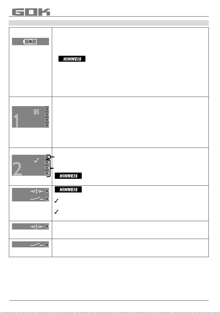
/LPLWLQGLFDWRUWHVWGHYLFH7\SH F-Stop®GWG-PG 1
WRWHVWWKHIXQFWLRQVRIWKHVDIHW\GHYLFHVOLPLWLQGLFDWRUDQGOLPLWLQGLFDWRU
ZLWKILOOLQJOHYHOVHQVRUV
CONTENTS
ABOUT THESE INSTRUCTIONS............................................................................................................. 1
MODIFICATIONS COMPARED TO PREVIOUS VERSION...................................................................... 2
PRODUCT-RELATED SAFETY ADVICE................................................................................................. 2
GENERAL PRODUCT INFORMATION.................................................................................................... 2
INTENDED USE ...................................................................................................................................... 2
DESIGN................................................................................................................................................... 3
ADVANTAGES AND EQUIPMENT .......................................................................................................... 3
START-UP............................................................................................................................................... 3
FUNCTION DESCRIPTION ..................................................................................................................... 4
OPERATION............................................................................................................................................ 5
TROUBLESHOOTING ............................................................................................................................. 5
MAINTENANCE....................................................................................................................................... 6
REPAIRS................................................................................................................................................. 6
DISPOSAL............................................................................................................................................... 6
TECHNICAL DATA .................................................................................................................................. 6
LIST OF ACCESSORIES......................................................................................................................... 6
WARRANTY ............................................................................................................................................ 6
TECHNICAL CHANGES .......................................................................................................................... 6
DECLARATION OF CONFORMITY FOR F-STOP PG-1–EMV–ROHS–DE–2014-09-15 ......................... 7
ABOUT THESE INSTRUCTIONS
•These instructions are part of the product.
•These instructions must be observed and handed over to the operator to ensure
that the component operates as intended and to comply with the warranty terms.
•Keep them in a safe place while you are using the product.
•In addition to this manual, respect the national regulations, laws and installation
guidelines.

/LPLWLQGLFDWRUWHVWGHYLFH7\SH)6WRS*:*3*
®
2 / 8
Part No. 15 097 52
MODIFICATIONS COMPARED TO PREVIOUS VERSION
•EC Declaration of conformity updated
PRODUCT-RELATED SAFETY ADVICE
Leaking liquid fuels such as fuel oil
•are hazardous to water
•may cause people to slip and injure themselves
•may ignite and cause burns
Capture all fuels during maintenance work.
May not be used in explosion-prone areas.
May cause an explosion or fatal injuries.
Must be installed by a specialist company in accordance with local industrial
health and safety regulations.
Installation outside the defined ex zone.
GENERAL PRODUCT INFORMATION
The limit indicator test device type F-Stop®GWG-PG 1 is intended for testing the functions of
limit indicators (B1 sensors) according to EN 13616 (in Germany, previously TRbF 511) that
are installed in tanks containing fuel oil or diesel. The limit indicator test device runs with three
batteries. The plug of the limit indicator test device is suitable for all limit indicator
connections.
INTENDED USE
Operating media
Diesel fuel
Waste oil
HVO
Fuel oil
BTL
Vegetable oil
Bio fuel oil
FAME
Industrial oil
You will find a list of operating media with descriptions, the relevant standards
and the country in which they are used at
www.gok-online.de/en/downloads/technical documentation.

Part No. 15 097 52
3 / 8
DESIGN
Heating process
Release
Switch-off time
Battery display
Short circuit
Disruption
Test button
Connection socket
Opening for plug contact
ADVANTAGES AND EQUIPMENT
•one-button operation
•microprocessor-operated device
•LED display
•display of switch-off time: ≤ 1.0 s; ≤ 1.1 s; ≤ 1.2 s; ≤ 1.3 s; ≤ 1.5 s and > 1.5 s
with completed dry-wet test of the PTC thermistor of the limit indicator
•connection socket suitable for all limit indicator connections
•includes carrying case
•includes battery charger
START-UP
The product is ready for use.
The function test of the limit indicator should be carried out by a specialised company or an
expert according to water laws.
Application example - Function test of the limit indicator by a specialised company
according to water laws.
Plug the connection socket of the limit
indicator test device type PG 1 on to the plug
of the limit indicator connection
Press and hold the TEST button
/LPLWLQGLFDWRUWHVWGHYLFH7\SH)6WRS*:*3*
®

4 / 8
Part No. 15 097 52
FUNCTION DESCRIPTION
Battery display
1. Battery state of charge
•Press and hold the TEST button:
green LED is lit: Release the Test button and test the functions
red LED is lit: Release the Test button and charge the battery
The red disruption LED is also lit.
2. Battery charging process
Connect the enclosed battery charger to the free connection:
•battery charging time approx. 15 hours
•while the battery is charging, the LED alternates between red and
green
•when the green LED remains lit, the battery is fully charged
3. Heating process
The limit indicator must be connected.
•Press and hold the TEST button:
only one of 4 yellow LEDs is lit
Heat must change to Release
4. Heating time
If the device is not released after 45 seconds, the measurement is
stopped and all 4 yellow LEDs are lit, cause:
limit indicator is still immersed limit indicator is defective
5. Release
•the first LED remains lit, the tank can be filled
•the other LEDs flashsee Check switch-off time
The release display with a lit LED is valid only when the
green battery display LED is also lit.
Observe the following in case of a short circuit or
disruption.
The heating phase must be at least 5 seconds.
If this is not the case, the PTC thermistor of the limit indicator is still
hot or is defective.
If the PTC thermistor of the limit indicator is still hot, allow it to cool
down and repeat the procedure.
6. Short circuit
If the current is >100 mA when you switch on, the test is stopped and
the red Short circuit LED remains lit.
7. Disruption
If the current is <10 mA when you switch on, the test is stopped and the
red Disruption LED remains lit.
/LPLWLQGLFDWRUWHVWGHYLFH7\SH)6WRS*:*3*
®

Part No. 15 097 52
5 / 8
OPERATION
Check switch-off time during the dry-wet test
If an LED flashes for Release, the limit indicator test device is ready to check switch-off time.
•If the PTC thermistor of the limit indicator is immersed in the operating medium, the LED
must change to one of the LEDs in Range 3 between ≤ 1.0 and ≤ 1.5 seconds.
•If this does not happen, the limit indicator is defective.
•The display > 1.5 seconds applies to the relevant switch-off time of the test basis specified
in the usability certificate issued by a building inspectorate (general building-authority
approval abZ or CE label) (see Table 1 Applicable standards).
1st yellow LED for heating flashes switch-off time ≤ 1.5 seconds
2nd yellowLED for heating flashes switch-off time ≤ 1.3 seconds
3rd yellowLED for heating flashes switch-off time ≤ 1.2 seconds
4th yellow LED for heating flashes switch-off time ≤ 1.1 seconds
1st green LED for release flashes switch-off time ≤ 1.0 seconds
1st redLED for short circuit flashes switch-off time > 1.5 seconds
Table 1: Temperature ranges and switch-off times according to the standard
Applicable standards
Temperature ranges
Switch-off times
EN 13616:2004
+5°C to +30°C
maximum 1 second
prEN 13616-2:2014
-25°C to +50°C
maximum 1.5 seconds
TRbF 511
-25°C to +50°C
maximum 2 seconds
If the function test indicates a switch-off time of >1.5 seconds, the limit indicator
must be replaced.
TROUBLESHOOTING
Fault signal
Action
LED lit in case of short circuit or
disruption
check polarity
connect plug to the limit indicator
connection properly
LED lit in case of short circuit and
disruption
the heating phase was too fast
(less than 5 seconds)
Red LED of the battery display is lit
connect the battery charger
Battery display alternates between green
and red during the function test
connect the battery charger
Release is not possible if the PTC thermistor of the limit indicator is immersed in the operating
medium of the tank.
/LPLWLQGLFDWRUWHVWGHYLFH7\SH)6WRS*:*3*
®

6 / 8
Part No. 15 097 52
MAINTENANCE
Apart from cleaning (with a dry cloth only), the limit indicator test device requires no care or
maintenance.
If the limit indicator test device has not been used for some time, if error
messages are displayed or as part of the test equipment monitoring process, we recommend
that you test the device with the function test adapter for limit indicator test devices (see List
of accessories).
REPAIRS
If the measures explained above under TROUBLESHOOTING do not result in regular
START-UP, and if there is no dimensioning problem, the product must be sent to the
manufacturer for a check. Our warranty does not apply in cases of unauthorised interference.
DISPOSAL
To protect the environment, our products may not be disposed of along with
household waste.
The product must be disposed of via a local collection station or a recycling station.
TECHNICAL DATA
Operating voltage Ua= (19 ± 0.3) V
Electrical resistance Ri= (160 ± 3.2) Ω
Battery charger Inlet:230 V AC
Outlet:12 V; 6 W
Length of cable 1.5 m
Protection type IP64 acc. to EN 60529
Ambient temperature -25 °C to +50 °C
LIST OF ACCESSORIES
Product description Part no.
Function test adapter for limit indicator test devices 15 097 60
Product description Part no.
car charging cable 15 097 10
WARRANTY
We guarantee that the product will function as intended and will not leak during
the legally specified period. The warranty term begins when the product is
handed over to the customer. The scope of our warranty is based on Section 8
of our terms and conditions of delivery and payment.
TECHNICAL CHANGES
All the information contained in these assembly and operating instructions is the result of
product testing and corresponds to the level of knowledge at the time of testing and the
relevant legislation and standards at the time of issue.
We reserve the right to make technical changes without prior notice. Errors and omissions
excepted.
All figures are for illustration purposes only and may differ from actual designs.
/LPLWLQGLFDWRUWHVWGHYLFH7\SH)6WRS*:*3*
®

Part No. 15 097 52
7 / 8
DECLARATION OF CONFORMITY FOR F-STOP PG-1–EMV–ROHS–DE–2014-09-15
/LPLWLQGLFDWRUWHVWGHYLFH7\SH)6WRS*:*3*
®

Regler- und Armaturen-Gesellschaft mbH & Co. KG
Obernbreiter Straße 2-16 • 97340 Marktbreit / Germany
Tel.: +49 9332 404-0 • Fax: +49 9332 404-43
E-Mail: info@gok-online.de • Internet: www.gok-online.de
8 / 8
Part No. 15 097 52
NOTES
Table of contents
Languages:
Other GOK Test Equipment manuals
Popular Test Equipment manuals by other brands

GDD Instrumentation
GDD Instrumentation TDLV instruction manual

BGS technic
BGS technic 9669 instruction manual

Millipore
Millipore M Air T Operation and maintenance instructions

Keysight Technologies
Keysight Technologies 85055A User's and service guide

Fluke
Fluke 7526A-156 Calibration manual

Pite
Pite LB 3980 user manual

ATEQ
ATEQ ADSE 550 user manual

KAWISH
KAWISH GIT600 user manual

EMIT
EMIT ESD Glove Test Fixture Installation, operation and maintenance

Hanna Instruments
Hanna Instruments HI 902 Color quick start guide

EUTECH INSTRUMENTS
EUTECH INSTRUMENTS PCSTestr35 quick guide

Emerson
Emerson Rosemount FS-HR-975 user manual