Goldacres ATV 200L User manual

ATV 200 & 300L
UV 400L
Operator’s Manual

2
GENERAL INFORMATION & SPECS ����������3
Operation �������������������������������������������������4
Calibration �����������������������������������������������4
Spray Application �������������������������������������5
Storage�����������������������������������������������������5
Identification ��������������������������������������������6
Dimensions ����������������������������������������������6
MAINTENANCE & TROUBLESHOOTING
FOR 12V UNITS���������������������������������������7
PARTS LIST ���������������������������������������������8
12v Pump Diagrams ������������������������������10
IOTA 20 PUMP���������������������������������11+12
Wheels & Tyres��������������������������������������13
MANUAL FOLDING BOOMS �������������������14
30m manual hose reel���������������������������16
AA30L GunJet ���������������������������������������17
Adjustable ConeJet Nozzle ��������������������18
IMPORTANT SAFETY MESSAGE FOR
OWNERS & OPERATORS������������������������19
SAFETY �������������������������������������������������20
The Operator �����������������������������������������20
Safety Precautions����������������������������������20
Safe use of chemicals�����������������������������21
Personal Protective Equipment (PPE) ����21
Safety Decals �����������������������������������������22
Identification �����������������������������������������22
TERMS & CONDITIONS ��������������������������24
Contact
Goldacres
1-3 Morang Crescent,
Mitchell Park Vic 3355
P: 03 5342 6399
F: 03 5342 6308
info@goldacres�com�au
Disclaimer
Any advice or recommendations given by Goldacres, Goldacres’ dealers, or employees is given in good faith and provided
based on the best information available to us� No liability or responsibility is accepted or implied as a result of any
information or advice tendered in this operating manual or by Goldacres its agents or employees� The end user accepts
all responsibility arising from that advice�
No part of this manual may be reproduced without written permission from Goldacres� All photographs and technical
information remain the property of Goldacres�

3
GENERAL INFORMATION
& SPECS
Tank:
All tanks are constructed from UV resistant
polyethylene� Polyethylene tanks have a very
high chemical resistance�
Due to the rotomoulding process, there can
be a variance in the overall dimensions of
the tank which in turn results in variations
to the tank capacity� For this reason, any
calibration markings should be used as a
guide only�
Filtration:
Filtration is a critical part of the sprayer’s
performance�
ATV200, 300 & UV400 are fitted with an
inline suction strainer� It is important that
the strainer is cleaned out regularly�
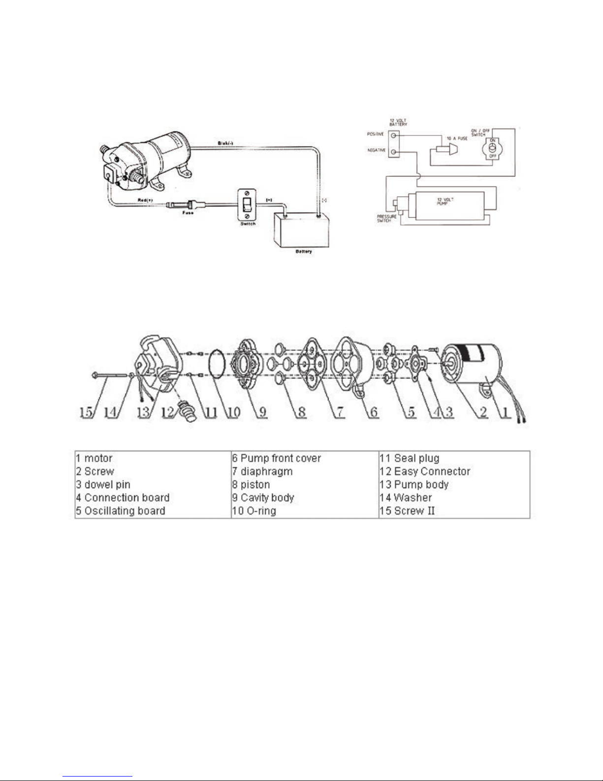
Pump:
The pump is critical to any sprayer
performance� Correct operation and
maintenance of the pump will ensure
the sprayer is able to perform to its
capabilities� Make sure the pump wires are
connected up to the correct terminals (red
to positive, black to negative)�
Always flush pump with clean water after
every use� Prolonged chemical contact can
severely damage valves, diaphragms and
seals�
Do not leave water in pump if sprayer is
to be left in a cold environment� The water
may freeze and cause damage to pump�
Empty pump of all water and cover the
pump to ensure this situation does not
arise� If this has not been done, and there
is a possibility there may be frozen water
in the pump, wait until any ice has thawed
before using the pump�
The 12 volt pumps are positive
displacement diaphragm pumps which
provide delivery upon demand�
They are self-priming and some models are
fitted with a pressure switch which senses
the outlet pressure of the pump� The
pressure switch turns the electrical power
off to the pump at a pre-determined high
pressure point�
As the outlet side of the pump is opened,
the pressure starts to drop and at a pre-
determined point (typically 40-75 psi)
contacts in the switch will lose causing the
pump to start automatically� The pump will
then pump until the pressure reaches the
shut-off pressure point�
CAUTION:
Do not adjust the pressure switch out so
that the pumping pressure exceeds the
maximum pressure for the pump�
If the flow demand is very low, the pump
may reach this high pressure point and
cause “cycling” (pump turns on and off
rapidly)�
This is not a problem unless the pump is
subject to continuous cycling within two
second intervals for long periods of time�
Altering the setting of the pressure switch,
or adjusting the agitation ball valve so that
there is some bypass back to the tank and
altering the adjustable conejet nozzle on
the gunjet will all remedy this situation,
depending on what is most suitable�
Chemical Induction:
Chemical should be put into the main tank
through the main tank lid� It is important to
ensure that chemical is thoroughly mixed
prior to spray application�
Nozzles:
As information regarding nozzles is specific
to those being used in your application,
no specific reference is made to nozzle
application rates or nozzle types in this
operator’s manual� Goldacres suggest the
use of a current nozzle selection catalogue
for reference to nozzle sizes, outputs, spray
patterns and general spraying information�
Goldacres recommends Lechler nozzles�

4
Operation
Connections
The following steps should be followed when
connecting to a power source:
1� Ensure that the battery is 12V DC
2� Connect the red connector to the
positive (+) terminal and the black
connector to the negative (-)terminal�
Filling
When filling the sprayer it is necessary to
use an external water source and wear the
appropriate PPE�
The following steps should be followed when
filling the tank:
1� Turn the pump off
2� Remove the tank lid
3� Add chemical as required� When
filling with water, after adding the
chemical, some agitation will take
place�
4� Use external water source to fill
main tank (Do not exceed the tank
capacity)
5� Replace the tank lid and ensure that it
is secure prior to switching on pump�
You are now ready to use the sprayer�
Calibration
All sprayers need to be calibrated and kept
in good condition� This will ensure that the
correct rate of chemical is applied to the
target�
Follow these steps to calibrate the sprayer:
1� Measure the spray width of the nozzle
on a dry surface (in metres)
2� Spray a test area at the intended
pressure and speed� Record distance
(in metres) covered in one minute
(minute)
3� Measure the nozzle output in litres
over one minute in a measuring jug
(l/min)
The spray volume can be calculated by the
formula below:
Nozzle output (l/min) x 10,000
Spray width (m) x speed (m/min)
Application rate (L/Ha) =

5
Spray Application
After completing the filling process, you are
now ready to start spraying�
NOTE: It is the responsibility of the
operator to ensure that the chemical mix is
sufficiently agitated and that the conditions
are right to start spraying� Operators must
wear the appropriate PPE�
1� Switch “On” pump
2� Allow pump to build pressure
3� Engage the trigger on the spray lance
to start spraying
4� Adjust the nozzle pattern as required
by rotating the nozzle in the
appropriate direction as required
5� Use a consistent speed or swath
pattern to ensure even coverage of
the target, or adjust the method of
application according to your target
Agitation
Agitation should take place when filling
or through another method as deemed
suitable by the operator�
Flushing
The following information is provided as a
general guide for flushing your sprayer after
a spray application
For more specific information regarding
flushing, and decontamination, specific
to the products that you are applying,
it is recommended that you consult the
chemical label or your chemical supplier�
1� Turn pump off
3� Add a quantity of fresh water to main
tank and then drain�
4� Add a quantity of fresh water, and
decontaminating agents if required,
to main tank�
5� Turn on pump, and spray fresh water
through the lance / gun� This will
ensure that fresh water has circulated
through the pump and lance�
6� Drain remaining contents of fresh
water� The sprayer is now ready for
storage�
Storage
If the sprayer is to be stored for a long
period of time without use, there are
several tasks that need to be performed�
1� Clean the sprayer thoroughly as
described under “flushing”
2� Store the sprayer out of direct
sunlight and where it will not be
affected by frosts
3� Ensure that the main tank is empty
4� Protect hoses and electrical
connections

6
Identification
When ordering parts or requesting service
information for your sprayer it is important
to quote the serial number of your machine,
and the purchase date, in order to receive
accurate information� The location of the
serial number is shown in the picture� This
serial number is stamped into the serial
number plate�
Dimensions
Please note: Dimensions are approximate only and may be subject to change without
notice�
Model Width
mm
Length
mm
Height
mm
Dry
Weight
200 Lt ATV with 12V pump & 3 Mt al� boom 1262 2213 1000 110 kg
300 Lt ATV with 12V pump & 4 Mt steel/
aluminium crossover boom
1262 2213 1000 115 kg
300 Lt ATV with engine driven pump & 4 Mt
steel/aluminium crossover boom
1262 2213 1000 120 kg
400 Lt UV with engine driven pump & 4 Mt
steel/aluminium crossover boom
1562 2378 1320 130 kg

7
Problem Possible Cause Possible Remedy
Pump not priming Valves damaged
Restriction in suction line
Restriction in delivery line
Diaphragm damaged
Check, clean and/ or replace
valve kit
Check suction line
Check delivery line
Replace diaphragm
Pulsating liquid
flow
Pump switching on and off due
to pressure switch
Pump sucking air
Alter settings of the pressure
switch
Alter the adjustable conejet
nozzle
Restricted pump delivery
Check suction line
Pump pressure
lower than expected
Suction filter screen blocked
Restriction in suction line
Valves damaged
Diaphragm damaged
Pump sucking air
Insufficient voltage
Clean screen
Check hoses, fittings and tank
outlet
Check/or replace valve kit
Check/or replace diaphragm
Check suction line
Check power supply
Pump stopping and
starting when not
in use
Valves damaged
Insufficient voltage
Damaged diaphragm
Check valves
Check power supply
Check/or replace diaphragm
MAINTENANCE &
TROUBLESHOOTING FOR
12V UNITS
The troubleshooting information is provided
as a reference when your sprayer is not
functioning correctly� To ensure that
you receive the best possible service,
it is recommended that you exhaust all
applicable troubleshooting solutions shown
prior to calling your dealer for service
advice�

8
PARTS LIST
ATV200/3 GA4905995 ATV300/4 GA4905975
8
Position Part No Description Quantity
1 GA4515600 ATV tank support mount 2
2 GA5023670 Mini hub & stub ass 2
3 GA5023665 Tyre nobby (22x11-8 x 6 ply) & 4 stud mini rim 2
4 300120 Filter, basket type, diam 305 x 245 deep 1
5 GA8500000
GA5023660
GA5023750
Tank, 200L, ATV low profile, green
Tank, 300L, ATV low profile, green
Tank, 400L, UV low profile, green
1
6 GA4522140 Tow ball mounting plate 1
7 GA5049100 Trailer coupling 50mm bolt on 1
8 GA5014955 Serial ID plate 1
9 GA5023895 GX100 Honda 1
10 5091D9 Udor 6:1 reduction gearbox suit Honda 3 hp 1
11 Iota20 Iota 20—20 l/min diaphragm pump 1
12 GA5012161 Narva split tubing 7mm (not shown) 0�5
13 GA5051245 Plastic P clamp 7�9mm (not shown) 0�004
14 GA5012049 Narva joiner red 2�5-3mm wire (not shown) 0�002
15 006530 Hose barb, elbow, 90 degree, 1/2 fly end x 13mm
hose, brass, Arag
1
1
31
2
32
3
33
4
34
5
15
25
35
6
16
26
36
7
17
27
8
18
19
20

9
9
Position Part No Description Quantity
16 GA5066085 15 mtr hose reel manual, 3/8” 1
17 GA5053250 Pressure gauge, small face, 0-400kPa 1
18 GA4900546 Gunjet, AA30, adjustable nozzle with fittings 1
19 GA5015971 Sticker Drain Only 1
20 GA5020620 Valve, ball, 12mm thread male/female inlet/
outlet, lever handle, SS
1
21 HB050-90 Hose barb, Elbow, 90 degree, 1/2 male thread x
1/2 hose, Banjo (not shown)
3
22 HOS12SIGHT Hose, clear, 12mm sight tube (not shown) 4
23 GA5007231 Hose clamp, cobra type, 1/2 (not shown) 2
24 HB075/050-90 Hose barb, elbow, 90 degree, 3/4 male thread x
1/2 hose, Banjo (not shown)
1
25 GA4534635 Bracket nozzle suit small booms 1
26 GA5013003 Pipe linch pin, 8OD x 60 long 1
27 GA4900093 Boom, 3m, with plumbing, 6 nozzle, manual fold 1
28 HOS13P Hose, pressure, 12mm, black, 250psi boom
pumps (not shown)
4�5
29 GA5000469 Hose clamp 1/2, SS (not shown) 13
30 GA5020355 Hose barb, brass, elbow, 90 degree, 1/2 male
thread x 1/4 hose (not shown)
1
31 GA5003783 50 x 50mm square tube insert black 4
32 GA5002911 35 x 35mm square tube insert black 1
33 GA5066540 Pump, electric 12V, 13�5 L/min 1
34 GA5022255 Electrical harness, 17 AWG wire in line fuse &
alligator clips
1
35 9620522 Valve, pressure regulating, polypropylene, 20 L/
min Arag
1
36 HOS12WSIGHT Hose, 12mm, clear, wire reinforced 0�5
11
9
10

10
12v pump wiring diagram
Important: Use 14 gauge stranded wire up to 6 metres from power source and 12 gauge
up to 18 metres from power source�
Connect Red to Positive (+) terminal and Black to Negative (-) terminal�
Spare parts available for GA5066540
Pathway 13.5 Lt/min pump:
GA5068305 Pressure switch
GA5068310 Viton seal kit
GA5068300 Diaphragm (Position 7)
GA5022470 Cavity body (Position 9)
GA5022465 O Ring (Position 10)
Also available: GA5068315 Filter to suit
Pump Diagrams

11

12
2
1
3
4
5
6
7
8
9
10
Number Description
1 Control valve
2 Pump
3 Gearbox
4 Choke
5 Pull cord
6 Fuel cap
7 Spark plug
8 Muffler
9 On/Off switch
10 Air damper
IOTA 20 PUMP Gear Box & Honda GX100 engine
290psi/20bar
20 l/min@550rpm
6:1 Reduction Gearbox
3hp Honda GX100 Engine
PART
NUMBER
DESCRIPTION
GA5023895 3hp GX100 engine
5091D9 Udor 6.1 Reduction
Gearbox to suit Honda GX
IOTA20 Udor Iota20 pump

13
Wheels & Tyres
All tyres used on Goldacres sprayers have
been designed to carry the maximum
loaded weight of the sprayer when travelling
at 20 km/h� The load capacity of the tyres
decreases as travelling speed increases so
it is important to heed this travelling speed
limit�
The tyre pressure also needs to be checked
regularly (check every 8 to 12 hours of
operation) and maintained at the required
tyre pressure�
There are many factors concerning the
appropriate tyre pressure for a particular
tyre and load� For example, the tyre size,
rim type, tyre status (driven or free rolling),
load, speed, haul length and ply rating all
need to be considered when determining
the tyre pressure�
To determine the correct tyre pressure:
1� Determine the maximum weight of the
sprayer when loaded (do not forget to add
the weight of the rinse water tank and the
foam marker tank when filled)�
2� Allow for each tyre to carry half the
maximum loaded weight of the sprayer
(this does not allow for any load on the
tractor pull or cyclical loading, which
provides for a safety margin)�
3� Determine what tyre size and ply is on
the sprayer�
4� Determine what appropriate tyre
pressure will provide the load capacity
required by the respective tyre as indicated
in the following table�
Goldacres Tyre Chart
Tyre Size Ply Rated Pressure (KPa) Rated Capacity (Kg)
22x11�00-8 nobby tyre 6 48 234

14
MANUAL FOLDING BOOMS
General information
The boom fitted as standard is part of the
Goldacres range of “folding booms” which
are available in sizes from 3 metres to 10
metres� These booms are constructed from
RHS and aluminium for strength and light
weight, the wings fold in for transport, and
jet bodies are mounted on stainless steel
brackets behind the boom for protection�
All booms, regardless of their design and
operating width, present certain safety
hazards in their operation� Please ensure
that you have read all safety precautions as
included in this manual and take particular
note of those re-listed below�
WARNINGS
• Never stand within the radius of boom
wings�
• Keep clear of overhead obstructions�
• CRUSH HAZARD - Keep hands clear of
moving parts when carrying out boom
fold and unfold sequences�
CAUTIONS
• Always ensure that there is adequate
room for the boom to open�
• Always ensure that the boom is
adequately supported when transporting�
Boom height
The standard nozzle spacing on Goldacres
booms is 500mm� For this spacing, the
optimum height the boom should be from
the object to be sprayed (with a 110° fan
angle nozzle) is 500mm�
There will be adequate spray coverage if
the nozzles are higher than this but this
increases the potential for drift� The spray
pattern is affected by many factors not
limited to, but including, gravity, pressure,
chemical composition and droplet size
so the pattern does not extend to the full
theoretical coverage� Refer to the TeeJet
nozzle selection catalogue for further
information on spray application and nozzle
technology
Boom height adjustment
Adjust the height of the boom by loosening
the nuts on the U-bolts clamping the boom
to the frame�
Raise or lower the boom to the desired
height and then re-tighten the nuts on the
U-bolts�

15
Operating instructions for
folding booms
1� Starting with the boom in the closed
position (Fig�1), pull each wing against the
spring in an out and down manner until
open and resting against the stop plate with
the adjustment bolt�
2� With both wings folded out into the open
position, (Fig� 2) check that boom is aligned
correctly�
3� If not aligned correctly, adjust position
with the adjustment bolts as necessary�
4� The 3 metre folding boom folds vertically
and the 8 & 10 Mt metre models includes
flip over ends that should be folded into the
open position prior to operation�
Figure 1: UV400 with 4 metre folding boom
closed�
Folding boom lubrication
Folding booms have a grease nipple fitted
at each pivot point� Grease these points
regularly with quality multi purpose grease�
Figure 2: 4 metre folding boom open

16
Part No� QT Y� DESCRIPTION
1 1 Base
2 1 Screw
3 1 Rubber Sleeve
4 1 Handle
5 1 Handle Sleeve
6 1 Link Lever
7 1 Washer
8 1 Washer
9 1 Spring
10 1 Washer
11 1 Flange A
12 1 Sleeve
13 1 Flange B
14 1 Axle
15 1 Fixed Washer
16 1 Outlet Fitting
17 1 Washer
18 1 Spring Washer
19 1 Washer
20 1 Spring Washer
21 1 Swivel Valve
(Inc� 2 valve O-ring)
22 1 Spring Washer
23 1 Washer
24 1 Nut
25 1 Screw
26 1 Washer
27 1 Washer
28 1 Nut
Ref�
No
PART
NUMBER
DESCRIPTION
1 GA5066080 30 Mt manual hose reel
2 GA4900546 AA30L GunJet with
adjustable brass ConeJet
3 5500X18 Adjustable ConeJet
4 GA5020875 Male tailpiece ¼˝ thread x
½˝ barb
AA43LA-10 AA43 GunJet
GA5023475 Turbo 400 Spray Gun
30m manual hose reel

17
AA30L GunJet
The gunjet trigger needs to be locked via
the trigger lock when not in use to prevent
the gunjet from spraying inadvertently�

18
Adjustable ConeJet Nozzle
The adjustable brass ConeJet nozzle
rotates through a half turn to provide spray
selection from wide angle,
finely atomized cone spray to
a straight stream spray�
Tip settings “A” and “B”
represent two extreme points
of rotation in tip adjustment�
ADJUSTABLE
CONJET TIP
NO.
PERFORMANCE LIQUID PRESSURE (bar)
1.5 2 3 4
A B A B A B A B
5500-X18
Standard
Capacity—l/min 0�79 2�61 0�98 3�18 1�14 3�67 1�40 4�54
Spray angle º 71 - 75 - 77 - 78 -
Max throw m 1�2 11�6 1�2 12�8 1�2 13�3 1�2 13�0
5500-X22 Capacity—l/min 0�98 3�14 1�21 3�79 1�40 4�54 1�70 5�30
Spray angle º 71 - 75 - 78 - 79 -
Max throw m 1�2 11�7 1�40 13�0 1�5 13�6 1�5 13�2
5500-X26 Capacity—l/min 1�17 3�71 1�40 4�54 1�63 5�30 2�01 6�43
Spray angle º 72 - 76 - 78 - 79 -
Max throw m 1�4 11�6 1�5 13�1 1�5 13�7 1�7 13�3

19
Do not load your ATV or other vehicle in excess of
the ATV manufacturer’s recommended carrying
capacity�
It is important to understand that any loads or
attachments you place on your ATV or utility
vehicle will have an impact on the stability and
handling characteristics and that you should
adjust your riding and operation of the ATV
accordingly�
Do not fill this spray tank or other equipment
to a level where the gross weight exceeds the
manufacturer’s recommended load limit of the
ATV�
Safety is Goldacres primary concern in the design,
manufacture, sale, and use of this ATV spray tank
and other equipment�
IMPORTANT: Failure to adhere to these
recommendations or follow these rules may
result in injury or death to the operator and/or
bystanders�
Anyone involved in the use or operation of the ATV
and ATV spray equipment should be aware of, and
trained in appropriate safety recommendations
including those contained in this manual�
CAUTION!
• Fully read the Owner’s Manual before
mounting this spray unit to an ATV or
vehicle�
• Before mounting to an ATV or vehicle
ensure that fitment complies with
weight restrictions as specified by ATV
or vehicle manufacturer�
• OVERLOADING the ATV or vehicle, or
operating it improperly, may cause an
accident, injury or death�
• Do not load the ATV in excess of the
load limit capacity of the ATV as
recommended by the manufacturer�
• Filling the spray tank when fitted to
the ATV will result in changes to the
handling and stability of the ATV�
• ATV tyres should be inflated to the
manufacturers recommended operating
pressures�
• Do not attach other equipment to the
ATV spray tank� This may exceed the
ATV spray tank’s designed capacity and
function�
• Reduce speed when operating the ATV
spray tank when tank is loaded�
• Allow for greater braking distances
when the ATV spray tank is loaded�
• To reduce possible ATV instability it is
recommended the ATV be stationary if
spot spraying on a slope or hill�
• Ensure the ATV or vehicle complies with
all relevant road regulations for use on
farm or public roads�
• Do not allow any other person to ride on
the ATV at the same time this ATV spray
tank is fitted�
• If spraying chemical, ensure you select
the right chemical for the application�
• Use relevant personal safety protection
(PPE) clothing and equipment when
handling chemicals� Refer to chemical
manufacturer’s label for requirements�
• Take care when spraying in windy
conditions� Spray drift may affect the
operator or adjoining vegetation�
• Do not allow use of this sprayer by
minors� Do not use the sprayer in the
vicinity of other people or animals�
IMPORTANT SAFETY MESSAGE FOR OWNERS
& OPERATORS

20
SAFETY
General
The following pages outline important
safety information� At Goldacres safety is
a high priority� These safety and warning
instructions MUST be followed to ensure
the safe operation of your Goldacres
equipment�
Explanation of key terms used in this
operator’s manual are:
Danger - You will be killed or seriously hurt
if you don’t follow instructions
Warning - You can be seriously hurt if you
don’t follow instructions
Caution - You can be hurt if you don’t follow
instructions
Note - Is used to notify people of
installation, operation or maintenance
information that is important but not
hazard related�
The Operator
All operators of this equipment should be
adequately trained in the safe operation
of this equipment� It is important that all
operator’s have read and fully understand
the operators manual prior to using this
equipment�
All new operators should be trained in an
area without bystanders or obstructions
and become familiar with the sprayer prior
to operation�
Safety Precautions
Warnings
• Any unauthorised modifications to this
equipment may affect its function and
create a serious safety risk�
• Never attempt to clean parts or nozzles,
by blowing with mouth�
• Never attempt to siphon chemicals, or
substances, by sucking�
• It is imperative that the vehicle
manufacturer’s specifications be
checked and all instructions for use
when transporting, or towing, be
adhered to at all times�
• Care should be taken when transferring
liquid into the tank to ensure that the
gross weight of the equipment does
not exceed the carrying, braking and/or
towing capacity of the vehicle to which
the equipment is attached as specified
by the vehicle manufacturer�
NOTE: 1 LITRE WATER = 1KG�
• Water weighs 1kg per litre, however
conversion factors must be used when
spraying liquids that are heavier or
lighter than water� Example: liquid urea
has a density of 1�28 kg/L and will
therefore be significantly heavier than
water if the tank is filled completely�
• Suitable care should be taken when
driving with the equipment attached
to the vehicle� Consideration should
be given to both the carrying capacity
of the vehicle and the gradient of the
terrain when determining the speed at
which the vehicle can be driven safely�
• Ensure that the maximum speed of
the vehicle, when loaded, is within the
vehicle manufacturers limitations�
• Ensure equipment is securely fastened,
or attached to the vehicle at all times�
• Never stand within the radius of boom
wings�
• Regularly check the pump mounting
bolts� The pump will always vibrate to
some degree when operating, and this
may work the bolts loose�
Cautions
• A supply of fresh water should be with
the equipment at all times�
• Standard polyethylene tanks are not
designed for use with diesel fuel or any
flammable liquid�
• Do not use this machine in ambient
temperatures exceeding 40 degrees
Celsius�
• Ensure that all bolts are tightened and
secured before operation�
• Where fitted, always ensure that
the boom (where fitted) is securely
supported when travelling�
This manual suits for next models
2
Table of contents
Popular Lawn And Garden Equipment manuals by other brands

Little Wonder
Little Wonder 2119 19, 2124 24, 2130 30, 223 Owner's manual and safety instructions

E-Z Trench
E-Z Trench Bedscaper EZ-8000 owner's manual

G-Tools
G-Tools G-kit Bonanza 0,35m2 installation instructions

Liberty Garden
Liberty Garden 870 owner's manual

EarthQuake
EarthQuake 9800 Series Operator's manual

Heliospectra
Heliospectra sensorHUB Setup manual