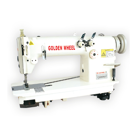
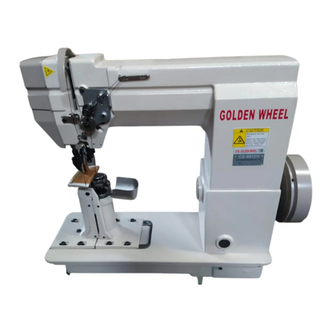
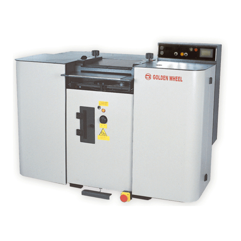
Golden wheel CS-471 User manual

GOLDEN WHEEL No.000001
Please read this Instruction Manual
carefully before using the unit in or
-der to get the most out of it and
to enjoy using it for a long time.
Please keep this Instraction Manual
at hand taking care not to lose it.
BEFORE OPERATION
1. Do not the machine even for trial before lubricatin
g
it.
2. Confirm that the voltage and phase
(
single or 3-phase
)
are correct by checking them againt the
ratings shown on the nameplate.
3. When running your machine for the first time after the set-up, check the rotational direction of
the handwheel.
・ Turn ON the power switch. Run the machine at a low speed while checking the rotational
direction of the handwheel.
(
The handwheel should turn counterclockwise as observed from the
handwheel side.
)
4. For the first month, run the machine at a speed of 600 s.p.m. or less.
CAUTIONS IN OPERATION
1. Keep your hands away from the needle when you turn ON the power switch or while the machine
is operating.
2. During operation, be careful not to allow your or any other person's head or fingers to come close
to the handwheel, V belt, bobbin winder or moter. Also, do not place anything close to them.
3. Do not run the machine with the finger guard, belt cover or any other protectors removed.
Eye guard is option.
4. Be sure to turn OFF the power switch and confirm that the motor is completely stopped before
removing the V belt.
5. Never remove the sewing machine from the table with the moter removed from the table.
SPECIFICATIONS
1] INSTALLING THE THREAD STAND
Assemble the thread stand, and install it to the right
-hand side of the far side of the table with screws
① (at 3 places).
CS-471
1-NEEDLE,TOP & BOTTOM FEED, LONG CYLINDER BED,
LOCKSTITCH MACHINE FOR EZTRA HEAVY-WEIGHT
MATERIALS WITH A SEMI-ROTARY LARGE-CAPACITY
SHUTTLE
INSTRUCTION MANUAL
Usage Pouches, bags, shoes, bag handles, Needle to used Schmetz 794Nm230
safty belts, etc. Needle system Nm130~Nm280
Sewing speed Max.800s.p.m. Thread #00~#8
Stitch length Max.11mm Stitch adjusting method Lever nut type
Lift of presser foot Hand lifter 12mm Lubrication method Hand oiling
Knee lifter 20mm Motor to be used 3-phase/single phase 400W
Thread take-up lever Cam-type thread take-up lever clutch motor(4P)
Needle bar stroke 56mm
- 1 -

2] INSTALLING THE HANDWHEEL
1. Fit handwheel ① close to the main shaft bushing,
rear ②.
2. Align the handwheel with thread groove ⑤ in the
main shaft. Tighten the first screw ③ of the hand
'-wheel, then tighten screw ④.
3] INSTALLING THE BELT COVER
1. Install two belt cover supports ① to the machine
arm.
2. Install belt cover B ② to belt cover supports ①
using screws ③.
3. Attach belt cover A ④ to belt cover B ② using
screws ⑤.
4.Fix belt cover A on the table using wooden screw
⑥ and washer ⑦.
4] ADJUSTING THE PEDAL
◆ Installing the connecting rod
Install connecting rod ② in place so that connecting
rod ② is at right angles to motor control lever ①.
Connect the connecting rod with pedal adjusting pla
-te ③ so that the rod is also at right angles to the
pedal.
◆ The angle of the pedal
The tilt of the pedal can be changed freely by adjus-
ting the length of the connecting rod.
To change the tilt of the pedal, loosen the adjusting
screw and advance or retract the connecting rod.
5] CLEANING
Waste thread, dust, dirt, etc., buld-up around the feed dog or the shuttle may cause malfunction
of the machine.
Clean periodically according to your frequency of use.
1. Clean around the feed dog after removing the throat plate.
2. Clean the inside of the shuttle race body by taking out the shuttle body after removing the
cover of the shuttle race body.
- 2 -

6] LUBRICATION
←Lubricate the sections
need to be lubricated
through two holes in
the side plate.
1. After uncrating, supply oil to the machine after cleaning it thoroughly.
2. When oiling all the sections requirring lubrication, after installayion of the machine has been comp
-
leted, wait for a while (approximately 10 minutes) so that oil can penetrate each section sufficientl
before starting continuous operation.
3. To operate the machine continuosly, apply two three drops of oil each section noted with an arro
w
mark in the above figure whenever starting operation in the morning and in the afternoon.
7] HOW TO INSTALL THE NEEDLE
◆ Be sure to power -off the motor.
The standard needle is a Schmetz 794, however an Orga
n
DY×3 can be used.
1. Turn the handwheel by hand and raise the needle bar t
o
its top position.
2. Loosen screw ① and insert the needle ② into the hol
e
until it will go no further.
( Insert the needle with its recess ③ facing directly to
the right-hand side )
3. Securely tighten the screw in the needle.
- 3 -

8] HOW TO TAKE OUT THE BOBBIN
1. Turn the handwheel by hand ( until the needle bar
comes down to the lowest point of its stroke ) so
that case retaining spring ① in the shuttle body
comes to recess to Ⅰ in the cover of the shuttle
race body.
2. When the case retaining spring is pressed, the bobbin
case ② will be opened and the bobbin ③ will pop out
of the case.
9] HOW TO WIND A BOBBIN THREAD
1. Raise the presser foot by the hand lifter lever.
2. Insert the bobbin into the bobbin winder spindle.
3. Thread the winder in the order illustrated and wind
the thread onto the bobbin four or five turns.
4. Push the bobbin winder trip latch Ⅰ down and the
bobbin starts rotating to wind bobbin thread with the
machine operated.
5. When winding of bobbin thread has been completed,
the winder trip latch will be disengaged and the bobbin
will stop autmatically.
◆ Adjusting the amount of thread wound round the bobbin
That amount of threa has already been adjusted so that thread can be wound round approximately nine-
tenths of the bobbin. If the amount is excessive or insufficient, adjust:
1. by loosen the adjusting screw and nut Ⅱ .
2. by turning the adjusting screw Ⅲ .
To decrease the amount, turn clockwise.
To increase the amount, turn counterclockwise.
3. After adjusting the amount of thread has been completed, tighten the nut to secure firmly.
◆ If bobbin thread is wound unevenly, move the bobbin winder thread guide Ⅳ forward and backward
so that thread can be wound evenly.
- 4 -

10] HOW TO INSTALL THE BOBBIN
1. After pulling out thread approximately 10 cm
from bobbin ① , put the bobbin into bobbin case
②.
2. Pass the thread through the threading groove Ⅰ
in the bobbib case.
CAUTION: Fit the bobbin in the bobbin case so
that the bobbin turns in the direction
of the arrow when the bobbin thread
is pulled.
3. Pass the thread through thread slit Ⅱ and pull
it up. Then the thread can be passed under the
thread tension spring ③ and pulled out.
4. Push the bobbin case into the original position
of holding the bobbin.
11] HOW TO THREAD THE MACHINE HEAD
1. Turn the handwheel by hand to move the
thread take-up lever to its top position.
2. Thread in the order illustrated and thread the
needle from the left to the right.
3. Pull out the thread, which has been threaded
in the needle, approximately 10 cm.
CAUTION: Thread the right-hand side of sec-
tion ⑧ when viewed from the face
plate.
12] ADJUSTING THE STITCH LENGTH AND
REVERSE STITCHING
◆ Adjusting the stitch length
To adjusting the stitch length, use the feed
regulator nut ① .
Align the upper end Ⅰ of the feed lever to the
scale indicating the desired amount.
To increase the pitch, turn the nut counter
-clockwise.
To decrease the pitch, turn the nut clock-
wise.
( To decrease the stitch length, turn the nut
while slightly pushing the feed lever down. )
◆ Reverse stitching
To carry out reverse stitching, push the feed
lever up by hand as far as it will go.
Reverse stitching can be done only when the
feed lever is pushed up.
③
Ⅱ
Ⅰ
①
②
③
⑦
⑤
④
⑥
⑧
⑨
⑩
①
②
①
Ⅰ
- 5 -

13] THREAD TENSION
◆ Adjusting the needle thread tension
Adjusting the needle thread tension by thread
tension nut ①.
To increase the needle thread tension, turn
the nut to the clockwise Ⅰ.
To decrease the needle thread tension, turn
the nut to the counterclockwise Ⅱ.
◆ Adjusting the bobbin thread tension
To adjust the bobbin thread tension
1. Loosen screw ①.
2. Adjust the bobbin thread tension by turning
screw ②.
To increase the bobbin thread tension, turn
the screw to the clockwise Ⅰ.
To decrease the bobbin thread tension, turn
the screw to the counterclockwise Ⅱ.
3. After the bobbin thread tension has been
adjusted, tighten screw ① firmly.
14] THE THREAD TAKE-UP SPRING
The standard stroke of thread take-up spring ①
is 8 to 15 mm.
To adjust the operating range;
1. Loosen screw ②.
2. Adjust the operating range by moving thread
the take-up spring adjusting plate ③ up and
down.
3. After adjustment has been completed,
tighten screw ② firmly.
15] ADJUSTING THE PRESSER FOOT PRESSURE
The standard height of presser spring regulator ①
30mm above the main unit surface.
The presser foot pressure for the presser foot and
walking foot can be adjusted according to the material
to be sewn.
To adjust the presser foot pressure
1. Loosen the presser spring regulator nut.
2. Turn the presser spring regulator clockwise to inc
-rease the pressure of the presser foot, or count
-erclockwise to decrease it.
3. After adjustment has been completed, turn the nut
firmly, making sure to keep it securely in place.
・ Use a minimum amount of required pressure.
①Ⅰ
Ⅱ
①
②
Ⅰ
Ⅱ
②
①
③
①
30mm
- 6 -

16] ADJUSTING THE HEIGHT OF THE FEED DOG
The advace amount of the feed dog from throat plate has
already been adjusted to 1.4mm.
To adjust the height of the feed dog according to the sewing
condition given.
1. Remove two screws ① in the shuttle race, and remove
shuttle race ②. Then remove shuttle ③.
2. Turn the handwheel to move shuttle driver ⑤ until screw
④ in the feed dog appears.
3. Loosen screw ④ in the feed dog, and adjust the height of
the feed dog by moving feed dog ⑥ up or down.
4. After the adjustment, firmly tighten screw ④ in the feed
dog.
17] ADJUSTING THE NEEDLE-TO-SHUTTLE RELATIONSHIP
◆ The position of the shuttle when it is recessed most.
When shuttle ① turns counterclockwise until it will go no
further and the shuttle and the shuttle race come in contact
with each other at point Ⅰ, a distance of 1mm should be
provided between the blade point of the shuttle and end face Ⅱ
of the shuttle race.
To adjust the position of the shuttle being pulled:
1. Turn the handwheel and stop turning when the shuttle turns
counterclockwise until it will go no further.
2. Loosen screw ②.
3. Align the blade point of the shuttle by turning the shuttle by
hand.
4. After adjustment has been completed, tighten screw ② firmly.
◆ Positioning the needle and shuttle
Turn the handwheel to make the needle bar ascend 5 mm from
its lowest position. At this time, blade point ③ of the shuttle
should be aligned with the center of needle ④.
( Reference value of the lowest position of the needle bar stroke )
The distance from the upper surface of the throat plate to the
lower end of the needle bar should be 25.9 mm with the feed pitch
set to 0 mm.
1.4mm
①
②
③
④
⑤
⑥
1mm
①
Ⅰ
Ⅱ
②
④
③
5mm
25.9m
- 7-

To adjust the position of the needle and shuttle
1. Loosen screw ⑤.
2. Loosen screw ⑥,and adjust so that marker dot Ⅲ
engraved on the eccentric cam of the vertical rod is
aligned with marker line Ⅳ engraved on the main shaf
t
Then, tighten screw ⑥.
3. Turn the handwheel toward you, and check the lifting
amount of the needle bar.
4. After the adjustment, securely tighten screws ⑤ and
⑥.
◆ The height of the needle bar
The correct height is that the distance from the blade poin
t
of the shuttle to the upper end of the needle eyelet is 2.5
m
when the blade point of the shuttle is aligned with the cent
e
of the needle.
To adjust the height of the needle bar
1. Set the feed pitch to 0 mm.
2. Turn the handwheel and stop turning it when the blade
point of the shuttle is aligned with the center of needle.
3. Loosen screws ⑦.
4. Adjust the height by moving needle bar ⑧ up and down.
5. After adjustment has been completed, firmly tighten scre
w
⑦.
◆ The needle-to-shuttle clearance
The clearance between the recess in the needle and the
blade point of the shuttle has already been adjusted to 0.25
~0.35 mm.
Point of the shuttle has already been adjusted to 0.35 mm.
Adjust the clearance between the needle and the shuttle b
y
replacing the shuttle race back.
( The shuttle race back comes in six different thickness in
addition to the standard thickness. )
To repace the shuttle race back
1. Remove two screws ⑨ in the shuttle race, remove shuttl
race ⑩, and remove shuttle ⑪.
2. Turn the handwheel until shuttle driver ⑬ is brought to t
h
position where shuttle race back ⑫ comes off.
Then replace the shuttle race back.
⑥
Ⅲ Ⅳ
2.5mm
⑧
⑦
0.25~0.35mm
⑩
⑨
⑪
⑬
⑫
⑤
- 8 -

◆ Clearance between the needdle and the shuttle driver
The clearance between the needle and the needle guide
of the shuttle driver has already been adjusted to the ra
n
of 0 through 0.05 mm.
To adjust the clearance between the needle and the shu
t
-le driver:
1. Loosen two screws ⑮, and remove thrust collar ⑭ of
the feed rock driving shaft on the feed bracket.
2. Loosen two screws ⑰, and move thrust collar ⑯ of t
h
feed rock shaft.
3. Loosen two screws ⑱ in the shuttle driving shaft thru
s
collar, screw ⑲ in the shuttle driving shaft front bushi
n
and small pendulum clamping screw ⑳.
4. Adjust the clearance by moving shuttle driving shaft fr
o
bushing 21 to the left and right.
5. After the adjustment has been completed, secure the
shuttle driving shaft thrust collar and the small pendul
u
making sure there is no axial play of the shuttle driving
shaft.
6. Finally, secure the respective thrust collars, making su
there is no play in the feed driving shaft and the feed
rock shaft.
The standard for adjusting the clearance between the needle
and the blade point of the shuttle
Use a standard Schmetz 794-Nm 230 needle.
1. Adjust the clearance Ⅴ between the convex section
o
needle 22 and shuttle driver 23 to 0.
2. Align the needle center with the blade point of the shu
ttle 24 and press the Ⅵ section of the needle against
the shuttle driver.
3. Adjust the clearance Ⅶ to a minimum, with the needle
pressed against the shuttle driver, making sure that th
e
needle does not contact the blade point of the shuttle.
・ By this adjustment the needle-to-shuttle blade point
clearance will be 0.25 ~0.35 mm.
⑯
⑰
⑭
⑮
⑳
21 ⑲⑱
22
23
24
Ⅴ
Ⅵ
Ⅶ
- 9 -

18] THE FEED DOG-TO-NEEDLE RELATIONSHIP
As standard timing of the feed dog, when the center
of the needle aligns with the blade point of the shuttl
e
with the feed pitch set to "0", the feed dog should m
o
ve from right to left by 1 mm when observed from th
e
face plate by moving the feed lever from the position
t
o set the normal feed pitch to the maximum value to
t
he position to set the reverse feed pitch to the maxi
-
mum value.
◆ To adjust the timing:
1. Loosen the two screws for the feed eccentric cam
①.
2. Adjust the timing to the standard one by aligning th
top end of screw ② in the feed eccentric cam with
marker line Ⅰ engraved on the main shaft.
3. After adjusting the timing has been competed, firml
y
tighten the two screws for the feed eccentric cam.
◆ The motion of the feed dog and needle
The center of the needle hole in the feed dog must
move with synchronized completely with the needle.
< How to adjust the needle sway>
If there is any lag in the motion of the feed dog and
t
hat of the needle, and the needle entry at the sewin
g
end is not same as that at the sewing start, perform
t
following adjustment.
1. Loosen clamping screw ④ in center shaft rear arm
③.
2. Move center shaft rear arm ③ toward/away from
y
and temporarily tighten the screw. At this time, mo
v
center shaft rear arm ③ away from you to decreas
e
the oscillating width of the needle bar frame,or pull
the arm toward you to increase it.
3. Slowly turn the handwheel by hand to confirm that
there is no lag between the motion of the feed dog
and that of the needle.
4. Repeat the above stated steps until the feed dog a
n
the needle move with completely synchronized.
5. after the adjustment, firmly tighten screw ④.
Dislocation in the moving direction Dislocation in lateral direction
◆ Needle entry point eith repect to the needle hole in the feed dog
If the needle fails to enter just the center of the needle hole in the feed dog even when
the motions of the feed dog and the needle are completely synchronized.
1. Check whether the needle is bent.
2. Check the direction of the dislocation either (A) or (B) as illustrated in the figure.
Ⅰ
①
②
⑥
⑤
④
③
Center of the needle
Dislocation
Moving direction
Center of the
needle hole in
the feed dog
Center of the needle
Lateral
Dislocation
needle hole in
the feed dog
Center of the
(A) (B)
- 10 -

◆ Adjusting the needle entry point
(A) When the needle entry point dislocates in the
moving direction.
1. Loosen clamping screw ⑥ in center shaft rear ⑤.
2. Align the needle with the center of the needle hole
in the feed dog.
3. After the adjustment, firmly tighten the screw.
(B) When the needle entry point dislocates in the lateral
direction.
1. Remove the screw in the face plate, and remove th
e
face plate.
2. Remove screws ⑯ and ⑱, and remove needle bar
frame presser plate ⑰.
3. Loosen screw ⑩ to allow needle bar frame guide
⑬
to move freely.
4. Loosen screws ⑦ and ⑧, and move needle bar fra
m
shaft bushing ⑨ until the needle is aligned with the
center of the needle hole in the feed dog.
5. Loosen screw ⑦, and retain needle bar frame shaf
t
bushing ⑨ so that needle bar frame shaft ⑭ is sec
-
ured at that position.
6. Make needle bar frame guide ⑬ come in slight cont
a
with the needle bar frame, and fix the guide at that
position by tightening screw ⑩.
7. Loosen screws ⑪ and ⑮, and position needle bar
frame presser retaining shaft ⑲ and needle bar fra
m
presser retaining plate ⑫ to the position where the
needle bar frame moves smoothly without play whe
n
needle bar frame presser plate ⑰ is attached to th
e
needle bar frame. Then tighten the screws.
( Caution )
After the needle entry point has been adjusted, be su
r
to confirm the clearance between the needle and the
blade point of the shuttle as well as the clearance bet
-
ween the needle and the finger. (Refer to pages 8,9 fo
r
hoe to adjust these clearances.)
19] THE MOTOR PULLEY AND THE V-BELT
Sewing speed 4 P
of the machine 50Hz 60Hz
(s.p.m.) Motor pulley O.
D
Belt length motor pulley O.
D
Belt length
600 65mm 55inches 55mm 54inches
800 85mm 56inches 70mm 55inches
1. Use an M-type motor pulley and V-belt.
2. The relationship between the motor pulley/belt length and the sewing speed of
the machine is shown in the table on the above.
(Caution) When using a single phase motor, use belts of 1 inch longer than those
shown in the table on the above.
Ali
g
n the needle with
the center of the needle
hole in the feed dog
⑧
⑨
⑩
⑪
⑫
⑬
⑭
⑮
⑯
⑰
⑱
⑲
⑦
- 11-

memo
- 13 -

GOLDEN WHEEL
CHEE SIANG INDUSTRIAL CO., LTD
No.32, Wu Chuan 7th Road, Wu Ku Industrial Area,
Wu Ku Hsiang 24248, Taipei Hsien, Taiwan.
Tel: 886-2-2999518 Fax: 886-2-2999519

Problem Cause Corrective measures
1. Thread often breaks ① Flaw is found out at thread path, needle ○ Remove flaw by smoothing flaw with fine
or thread splits finely, point, shuttle blade point, or needle eyelet. paper file.
correct stitch cannot ② Improper finish around the recess in the ○ Replace the needle with a new one.
be formed (half-finished needle.
stitch) ③ Excessively tightened needle thread tension. ○ Adjust the needle thread tension.
④ The needle interferes with the blade point ○ Refer to "17.Adjusting the needle-to-
of the shuttle. shuttle relationship".
⑤ The timing of the needle and the shuttle is ○ Refer to "17.Adjusting the needle-to-
too early or too slow. shuttle relationship".
⑥ Due to heat generated by the needle. ○ Decrease the sewing speed of the mach
-ine. Use silicone oil.
⑦ Excessive height difference at stepped ○ Increase the amount of movement of
section. the thread take-up spring.
2. Stitches are frequently ① The needle-to-shuttle blade point clearance ○ Refer to "17.Adjusting the needle-to-
skipped is excessive. shuttle relationship".
② The timing of the needle and the shuttle is ○ Refer to "17.Adjusting the needle-to-
too early or too slow. shuttle relationship".
③ The presser bar pressure is insufficent. ○ Tighten the presser adjuster screw.
④ The distance from the upper end of the needle ○ Refer to "17.Adjusting the needle-to-
eyelet to the blade point of the shuttle is not shuttle relationship".
proper.
⑤ The needle is improperly selected. ○ Replace the needle with a one-count
lower needle.
⑥ The amount of movement of the thread take- ○ Decrease the amount of movement of
up spring is excessive. the thread take-up spring.
⑦ Overheated needle or shuttle. Thread is not ○ Use silicone oil.
pulled smoothly.
⑧ Reverse stitching is made at low speed on light ○ Wind the needle
weight material using nylon thread. thread around the
needle.
3. Improper thread tension, ① Poor finish of the thread path. ○ Smooth the surface with a fine paper
irregular stitch, excess- file or using a buff.
ive bobbin thread tension ② The bobbin slides unsmoothly. ○ Replace the bobbin or the shuttle.
③ Weak bobbin thread tension. ○ Adjust the bobbin thread tension.
④ Bobbin thread is wound too tightly. ○ Decrease the tension of the bobbin
thread winder.
⑤ Needle thread flaps.(Needle thread flaps and ○ Thread the tension
comes out of the thread tension disc due to guide bar as illustrated
excessive needle thread tension or is caught right.
in other parts.)
⑥ Too thin bobbin thread is used to combine with ○ Use silicone oil.
needle thread.
4. Poor gloss of the needle ① Excessive height difference at stepped section ○ Use silicone oil.
5. Inconsistently finished ① Needle is too thick. ○ Replace the needle with a thinner one.
seam(stitches are not Use cutting point needle
made straight but made
such as "ミ")
6. Bobbin thread tension ① The bobbin thread tension spring of the shuttle ○ Clean by removing the bobbin thread
cannot be increased has become dusty or dirty. tension spring.
7. The belt slips (Motor sto ① THe V belt is degraded. ○ When degradation is found out to the
-ppage occurs, if an elec V belt, such as wear, cracking, etc.,
-tronic-stop motor is replace with a new one.
used.) ② The V belt tension is not enouth. ○ Adjust the slack amount in the V belt
to 10mm/1kgf.
Handwhee
10mm
1kg
f
Motor
ll
- 12-
Table of contents
Other Golden wheel Sewing Machine manuals

Golden wheel
Golden wheel CS-5900 User manual

Golden wheel
Golden wheel CS-9010 User manual

Golden wheel
Golden wheel CS-2160N User manual

Golden wheel
Golden wheel CS-5940 User manual

Golden wheel
Golden wheel CSA-1371CTLD User manual

Golden wheel
Golden wheel CS-8810 Assembly instructions

Golden wheel
Golden wheel CS-S868 User manual