Goldline SAB Series User manual

GOLDLINE GAS COOKTOP
(SAB SERIES)
USER MANUAL

Page 2
Built-in Gas Hobs
Installaon and User manual
Model numbers covered in this manual:
SAB301GL, SAB302GL, SAB2GL, SAB3GL, SAB402GL
SAB603GL, SAB4GL SAB704GL, SAB5GL
Content
Safety instructions———————-2
Product description———————4
Specifications Table—————–—6
Installation ———–——————–8
Start Using your cooktop———–—13
Maintenance and troubleshooting—-15
Servicing———————————19
NOTE: This User Instrucon Manual contains important informaon, including safety
& installaon points , which will enable you to get the most out of your appliance.

Page 3
This manual explains the proper installation and use of your appliance, please read it carefully before using even if you are familiar with
the product. The manual should be kept in a safe place for future reference. In case of failure, only the Authorized Technical Service
may repair this hob. Otherwise the guarantee will be null and void.
Warning
General safety
The appliance may only be installed and connected by trained, Authorised persons.
Built-in appliances may only be used after they have built in to suitable built-in units and work surfaces that
meet standards.
In the event of faults with the appliance or damage to the glass toughened (cracks, scratches or splits), the appliance
must be switched off and disconnected from the electrical supply, to prevent the possibility of an electric shock.
Repairs to the appliance must only be carried out by trained Authorised persons.
The technical and identification data for the hob figure on the reference plate fixed to the appliance.
This reference plate must be consulted before making the electrical connections.
The electrical connections must be made by specialist aware to the legal and regulatory, requirements in each
country.
If the cable is damaged in any way it must be replaced by the manufacturer or after sale service or by authorized
technical staff, to avoid hazard. Correct use
People (including children) who, because of their physical, sensory or mental capabilities or their inexperience or
ignorance are not able to use the device safely, should not use this device without supervision or instruction by a
responsible person.
This appliance should be used only for normal domestic cooking and frying of food.
The appliance must not be used as a work surface or as a storage surface.
Additions or modifications to the appliance are not permitted.
Do not place or store flammable liquids, highly inflammable materials or fusible objects (e.g. plastic film, plastic,
aluminum, cardboard) on or near or below cupboards and drawers the appliance.
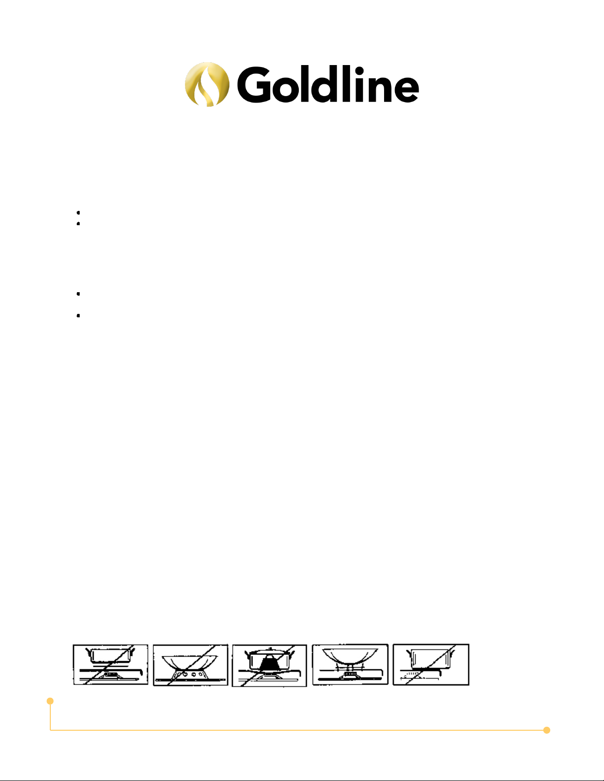
Do not heat an empty pan on the appliance.
Do Not Use this Appliance as Space Heater
We don’t recommend after market lids or cover fitted with this product.
When the appliance is installed in a marine craft or in a caravan, it shall not be used as a space heater.
Do Not Modify This Appliance.
Children's safety
The cooking zones will become hot when you cook. Therefore, always keep small children away from the appliance.
The appliance is not intended for use by young children or infirm persons without supervision.
Young children should be supervised to ensure that they do not play with the appliance.
Safety during use
Remove stickers and film from the glass ceramic.
There is the risk of burns from the appliance if used carelessly.
Cables from electrical appliances must not touch the hot surface of the appliance or hot cookware.
Overheated fats and oils can ignite very quickly. Warning! Fire hazard!
Switch the cooking zones off after each use.
Users with implanted pacemakers should keep their upper body at least 30 cm from cooking zones that are switched
on.
Risk of burns! Do not place objects made of metal, such as knives, forks, spoons and saucepan lids on the cooking
surface, as they can get hot.

Page 4
Safety Instructions and Product Description
Do not use or store flammable materials in the appliance storage drawer or near this appliance.
Do not spray aerosols in the vicinity of this appliance while it is in operation.
For LPG appliance:- Do not use this appliance in a marine craft or caravan.
This hotplate must be installed in accordance with: AS 5601 -Gas Installations ( for Australia) NZS 5261 – Code of
Practice for the Installation of Gas Burning Appliances and Equipment ( for New Zealand) Local gas fitting regulations
AS/NZS 3000 – Electrical Installations ( Wiring Rules) Building codes Any other relevant statutory regulations.
Check the gas type label on the underside of the hotplate, adjacent to the gas connection to ensure it corresponds to
the installation gas supply. If in doubt contact the supply authority.
The power supply cord (supplied) must not touch against any hot surfaces and must be placed so that its temperature
does not exceed 75 degrees at any point along its length.
After connecting to gas, check for leaks using soapy solution, never a naked flame.
Where a flexible hose assembly is used, ensure it is approved to AS/NZS 1869, Class B or D. Any hose assembly
used must be restrained from accidental contact with the flue outlet of an under bench oven. The hose is not to exceed
1.2m in length.
If you are required to transport the Goldline product to the Company or its service agent, you must ensure it is safely
disconnected by a qualified tradesman and securely packed and insured. The Company does not accept any
responsibility for loss or damage of the Goldline product prior to it being received by the Company or its service agent.
Please dispose or recycle any packaging material.
How to avoid damage to the appliance
The glass toughened can be damaged by objects falling onto it.
The edge of the glass ceramic can be damaged by being knocked by the cookware.
Cookware made of cast iron, cast aluminum or with damaged bottoms can scratch the glass toughened if pushed
across the surface.
Objects that melt and things that boil over can burn onto the glass ceramic and should be removed straightaway.
Do not use the cooking zones with empty cookware or without cookware.
To avoid damaging cookware and glass ceramics, do not allow empty saucepans or frying pans to keep heating by the
hob.
The ventilation gap of 5mm between the worktop and front of the unit underneath it must not be covered.
Do not modify this appliance.
This unit is not designed to be used with any aftermarket lids or covers.
Safety when cleaning
For cleaning, the appliance must be switched off and cooled down.
For safety reasons, the cleaning of the appliance with steam jet or high pressure cleaning equipment is not permitted.
Disposing of the device When disposing of the device, do not bring it to regular municipal waste containers. Instead, bring it to
electrical and electronic waste recycling and reuse center. A relevant label has been put on the device, its
instructions manual, or the package. The device has been manufactured of recyclable material. By bringing old
device to recycling collection center, you show that you care about nature. Ask your local environmental care
authority for information on location of such facilities.

Page 5
Model number. Shown
SAB4GL
Wok — Wok Burner
R — Rapid Burner
SR — SemiRapid Burner
Aux — Auxiliary Burner
Tempered glass Trivet
WOK
AUX
SEMI RAPID
WOK
CONTROL KNOBS
Layout for different models will vary.
Please see SPEC table for burner details of each model.
Accessory Name Picture ( for reference only, physical unit maybe different)Quantity
User Manual
1
Installation clip
3
Screws ST4.2x18
3
Adhesive sealing tape
3
Natural gas regulator
1
Test point adapter
1

Page 6

Page 7
Bench cut out and cooktop dimension by model number.
According to Australian regulations, the minimum clearance between a gas cooktop element or burner
component is:
• 600mm of vertical clearance to a combustible surface, and 200mm of horizontal distance to a verti-
cal surface. If these measurements can't be met, the surface in question must be protected with a fire
resistant material in accordance with AG/601.
• 600mm to a rangehood
• 750mm to an exhaust fan.
It's worth noting that with exhaust fans and rangehoods there isn't a specific clearance requirement un-
der the Building Code of Australia. Like all appliances though, these need to be installed according to
statutory requirements, and so that the installation meets the manufacturer’s specifications.
The Standard also states that the horizontal clearance from a hotplate or burner to a vertical combus-
tible material (like an acrylic splashback, for example) should be over 200mm. If not, the splashback or
other material needs to be protected with a non-combustible material to a height of 150mm for the full
length of the cooker.
See specs table on page 6 for details of bench cut out and other important information for each model.
The following is a guide to your installation layout.

Page 8
3. Fit burners and trivet. Replace burners and ensure they are correctly reposioned over the ignitor( S) and \ thermocouple
( T). The ignitor( S) must be clean for trouble free sparking. Test burner ignion and burner ame for correct operation, If
burner is placed correctly it will not rotate on its supports.. The DCC( Wok) burner( diagrams below) does not t over the
igniter or thermocouple but must be placed on its supports.
2. Place burner box Apply the adhesive sealing tape to the underside lip of the burner box. Shown at G opposite.
Place burner box into cutout hole and t clamping brackets to clamp the hotplate to the bench.

Page 9
4. Electrical connecon. Install a 10 amp general purpose outlet( GPO) in accordance with relevant electrical standards and/or
codes of pracce applicable. The power supply cord( supplied) must not touch against any hot surfaces and must be placed
so that its temperature does not exceed 75℃ at any point along its length. Aer having installed the hotplate, the GPO
must always be in an accessible posion.
Wiring diagram for:
SAB4GL,
SAB4GLH,
SAB704GL,
Wiring diagram for:
SAB5GL
Wiring diagram for:
SAB301GL,
SAB302GL,
SAB402GL
SAB2GL
Wiring diragram for:
SAB3GL
SAB603GL

Page 10
5. Gas connecon
Install in accordance with relevant gas standards and/or codes of practice applicable. Connect the elbow fitting to the appliance gas
manifold connection, and check that seals between the elbow and manifold connecon are in place and in good condion.
For Natural gas : connect the natural gas appliance regulator (pictured opposite) with integral test point using approved gas thread tape or
compound to the elbow ng.
For Universal LPG : connect the Test point adapter (pictured below) with integral test point using approved gas thread tape or compound to
the elbow ng.
LPG testpoint
Natuaral Gas Reguator
i
n
l
e
t
c
Ensure the supply connection point, test point and natural gas regulator adjustment screw (for Natural gas installation) are acces-
sible for testing and/or adjustment with the hotplate in the installed position. Where a flexible hose assembly is used, ensure it is
approved to AS/NZS 1869, Class B or D with max. length of 1.2m. Any hose assembly used must be restrained from accidental
contact with the flue outlet of an under bench oven. This hose assembly shall be suitable for connection to a fixed consumer
piping outlet located as follows: Hotplates at a point 800 mm to 850 mm above the floor and in the region outside the width of the
appliance to a distance of 250 mm.
Note: If clearance between side and rear walls and periphery of the burner is less than 250mm, the walls must be protected with a
non-combustible The protection must minimum distance of 450mm above the burner. Horizontal surfaces less
than 650mm vertically above the hotplate must also be protected.

Page 11
ADJUSTING THE BURNER MINIMUM FLAME HEIGHT : NOTE: This adjustment can only be performed by authorised service per-
sonnel. The minimum burner ame is factory adjusted for the gas type stated on the gas type label adjacent to the gas connection
and should not require adjustment. Adjustment may be required if the hotplate has been converted from Natural gas to Uni-
After connecting to gas, check for leaks using soapy solution, never a naked flame. Fit the duplicate data plate ( supplied in separate bag)
on a surface adjacent to the hotplate, for example, the inside of the cupboard door so it is clearly visible for any service technician.
SETTING THE GAS PRESSURE : Fit a manometer with a 6 mm rubber hose to the test point on the regulator ( for natural gas). For all the mod-
els, light all burners on and adjust test point pressure to 1.00 kPa. Turn burners o and on again and recheck the pressure is same as set previ-
ously or adjust as required. TEST FOR CORRECT OPERATION : After installation and test point setting, each burner ignition and operation must
be tested individually and with all burners operating. This testing must be done by the installer before leaving.

Page 12
The hotplates are fitted with mains powered electronic spark ignitors, so must be connected to mains power supply ( i.e. nomi-
nal 220 -240 V ac) to operate. If power is not available, the hotplate will still work but the burners will have to be lit with a
match or similar. Depressing the gas control knob of any burner will activate the spark ignition for all burners. To light the
burner, turn the gas control knob to the High Flame setting of the burner to be lit, while at the same time depressing the gas
control knob to activate the spark ignition. Once the burner is alight continue to depress the gas control knob for 5 – 10 sec-
onds to allow the flame safeguard to activate. If when you release the gas control knob, the burner flame goes out the flame
safeguard has not heated up enough so repeat the ignition procedure after waiting 1 minute for gas to disperse. If problems
with burner lighting persist, refer to the TROUBLESHOOTING section of these instructions. If power is not available, light a
match or similar, then turn the gas control knob for the burner to be lit, to the High Flame setting. Once again if problems with
burner lighting persist, refer to the TROUBLESHOOTING section of these instructions. When burner lights, adjust desired
BURNER AND UTENSIL CHOICE
The maximum utensil ( pan) diameters in millimetres ( mm) for each burner are:
For Natural Gas hotplates
Auxiliary ( small) and Semi-Rapid ( medium) = 195 mm
Rapid ( large) = 230 mm
DCC ( wok) = 400mm
For Universal LPG hotplates
Auxiliary ( small), Semi-Rapid ( medium) and Rapid ( large) = 195 mm
DCC ( wok) = 270 mm
The minimum utensil (pan) diameters in millimeters (mm) for each burner are:
Auxiliary (small)=80 mm
Semi rapid ( medium)= 140mm
Rapid (large) and Triple ring ( wok)= 195mm

Page 13
For the best efficiency and to ensureutensil handle does not over heat, place
the utensil centrally on the burner and adjust the flame height so all the flame
remains under the utensin.
NOTE: Enclosure may be be circular or sqaure

Page 14
Cleaning and maintenance should be carried out with the appliance cold, especially when cleaning the enam-
el parts. Avoid using alkaline or acid substances (lemon juice, vinegar etc..) on the surface.
CERAMIC GLASS PANEL
The ceramic glass hob of the hotplate must be cleaned regularly ( e.g. weekly) to ensure long life expectancy of
the hot plate.
Ensure the hot plate has cooked. Wash down with warm soapy water and rinse with clean water.
Dry with a warm cloth.
NOTE: Ensure that wiping is done along the grain of the ceramic glass top to prevent any unsightly crisscross
scratching patterns from appearing.
TRIVETS (UTENSIL SUPPORTS
Enameled parts must only be washed with a sponge and soapy water or
with non-abrasive products. Rinse with clean water.
Dry with a clean dry cloth.
BURNERS
Remove trivets from hob. Ensure that burners are cool. Remove the
burners enameled cape and aluminum burner crown (F)
Wash down with warm soapy water and rinse with clean water.
Dry with a clean dry cloth.
Use a cotton bud, toothbrush or some other similar item to clean out any
incrustations or dirt from the four holes marked (H)
Replace burners and ensure they are correctly repositioned over the
igniter (S) and thermocouple (T). The igniter (S) must be kept clean
for trouble free sparking. Test the burner ignition and burner flame
for correct operation.
The DCC (wok) burner ( bottom diagram) does not fit over the ignit-
er to thermocouple for positioning but must be placed on its sup-
ports.
If the burner is in the correct position it will not rotate.

Before Installation :
Before cung into any bench tops, ensure the minimum clearances to walls, adjacent surfaces and overhead surfaces required by the
relevant gas appliance installaon code ( see above) will comply. Dimensions are specified in millimeters ( mm)
Overhead cupboards and range hood = 600 mm. Side and rear clearance = 200 mm to any burner edge. Overhead exhaust/When
you have installed the hob, make sure that
The GPO (general purpose outlet) must always be in an accessible position.
The supply connection point, test point and natural gas regulator adjustment screw (for Natural gas installation) are accessible
for testing and/or adjustment with the hotplate in the installed position.
TO BE INSTALLED ONLY BY AN AUTHORIZED PERSON
Place burner box Apply the adhesive sealing tape to the underside lip of the burner box. Shown at G opposite. Place burner box into cutout
hole and t clamping brackets to clamp the hotplate to the bench.
Electrical connecon. Install a 10 amp general purpose outlet( GPO) in accordance with relevant electrical standards and/or codes of
pracce applicable. The power supply cord( supplied) must not touch against any hot surfaces and must be placed
so that its temperature does not exceed 75 degree at any point along its length. Aer having installed the hotplate, the GPO must
always be in an accessible posion.
GAS CONVERSION INSTRUCTIONS:
The manufacturers servicing instrucons detail how authorized personnel may convert the hotplate from Natural gas to LPG or from
LPG to Natural gas. Contact the manufacturer or agent as required.
Converng to a dierent gas type
When converng from LPG to NG ensure that the LPG test point is removed and replaced
with an approved NG regulator supplied in the kit. The test point pressure must be adjusted
to 1.00 kPa with the largest burner operang at on maximum ame.
GAS TYPE WOK
(OUTER)
WOK
(INNER)
SEMI RAPID AUXILIARY
LPG 1.10 0.50 0.69 0.50
NG 1.80 0.8 1.18 0.9
HKTG 3.00 1.45 1.75 1.30
Table of injector sizes.
Page 15

Page 16
Changing the jets:
1. Remove pan supports, burner heads and cups.
2. Use a 7mm socket to unscrew and remove the jets, replacing them
with those supplied in the kit. Ensure that the correct jets are fitted
to the corresponding burner ( see spec table)
3. Fit the gas type label supplied with this kit next to the gas connec-
tion point and remove existing label.
Setting the minimum flame level:
1. Remove panels, knobs and water dish.
2. Reasemble the burner heads, caps and knobs.
3. Light one of the burners and turn the tap to maximum flame.
4. Use a thin blade screwdriver to turn the by-pass screw located on
the right of the gas tap shaft as show in the image on the right.
Turn the by-pass screw fully counter clockwise. The result
should be a small, stable flame which is uniform around the entire
burner ring, if not turn the by-pass screw clockwise until satisfied
with the flame.
5. Check that the burner does not go out when the tap is turned
quickly from the maximum to minimum position.
6. Repeat for each burner.
7. Remove the burner heads caps and knobs
8. Reassemble panels, burner heads, caps, knobs and pan supports.
Gas Conversion (NG to LPG)
If the required gas conversion kit is not supplied with
your appliance, Gas conversion shall only be undertaken
by an authorized person.
The NG to LPG conversion kits contains:
• Test point adaptor
• Auxiliary jet dia 0.50mm
• LPG gas type label
• Semi rapid jet dia 0.65
• Wok jet dia 0.5mm (Inner) + dia 1.10mm (Outer)
GAS CONVERSION ( LPG TO NG)
If the required gas conversion kit is not supplied with your appliance, you can
order one from GOLDLINE.
Gas conversion shall only be carried out by by an authorized service techni-
cian.
The conversion kit contains:
-NG regulator -NG Gas type label
-Auxiliary jet dia 0.9mm
-semi Rapid jet dia 1.1mm
-Wok jet dia 0.8mm ineer and 1.8mm outer

Page 17
TROUBLESHOOTING
Servicing of the hotplate must only be done by an authorized service representative (see back of this booklet)
and the hotplate must not be modified. Power must be disconnected before any servicing or maintenance is con-
ducted.
Abnormal conditions include:
• Excessively yellow or sooting flame type.
• Flame lifting off the burner ports.
• Flame lighting back into the burner (normally associated with a popping sound)
• Objectionable odour of the flames combustion products.
Should a faulty condition develop in the hotplate that is not described above, refer to the following table first for
possible causes and remedies prior to contacting an authorized service representative. Servicing beyond the
remedies listed shall only be undertaken by an authorized service representative.
FAULT CAUSES REMEDY
Burner will not light
1. Air in gas line
2. Blockage in line
3. Ignition not sparking
4. Flame failure device faulty
5. Check the battery
(applicable to DC version)
1. Purge gas line
Trace back and clear
3. Check lead and electrode
4. Replace thermocouple and test
5. Replace the battery
Burner lights
back to injector
1. Excessive lint up burner
mixing tube
2. Excessive gas pressure
1. Remove and clean burner
2. Check gas regulator pres-
sure. Adjust if necessary.
Burner has ex-
plosive ignition
1. Excessive gas pressure
1. Check gas regulator pres-
sure. Adjust if necessary.
Ignitor not sparking
1. Electrode gap
2. Ignition connection
1. Check gap, adjust if
not between 4-5mm
2. Check connection to igni-
tor, replace if faulty.
FAULT ISOLATION CHART

Page 18
Access to By Pass Screw
- Light the burner and turn to minimum setting (marked small flame).
The flame should
minimum setting and should not extinguish when passing from maximum setting to low
setting.
- If adjustment is necessary, remove the control knob by pulling upward. The bypass screw
is accessible
via the control knob Turn
the bypass screw anti-clockwise to increase the turn-down rate
Access to manifold, gas taps and burner assembly
- Remove glass hob and control knobs.
- To remove gas cocks. Unscrew the locking nut (between cock and burner). Remove
screws, the cock can now be removed from the manifold.
If access to the barrel is required, remove two screws, which retain spindle to body. If lu-
bricating the mechanism use Regosine Moly LM or other approved grease.
To replace electrode
- Remove screw from the clamp holding the electrode and thermocouple and note
the
adjustment setting height of each. Replace electrode and then fit clamp and screw.
SERVICING INSTRUCTIONS
WARNING! DANGER 240
VOLTS 50Hz
DISCONNET POWER BEFORE SERVICING UNIT DO NOT
MODIFY THIS APPLIANCE
MINOR ADJUSTMENT

Page 19
1.1 In this warranty:
1.1.1 Australian Consumer Law means the law as set out in Schedule 2 of the Competition
and Consumer Act 2010;
1.1.3 Consumer means a “consumer” as that term is defined in Section 3 of the Australian
Consumer Law as the original purchaser of a Goldline product;
1.1.4 Consumer Guarantees means the guarantees under the Australian Consumer Law;
1.1.5 You means the Consumer.
1.2 Nothing in this warranty affects any person’s rights under the Australian Consumer Law.
The benefits to any Consumer under this warranty are in addition to the rights and remedies
available under any Consumer Guarantees.
1.3 Subject to the other clauses of this warranty, the Company warrants to the Consumer that
the Goldline product will be free of manufacturing defects and will perform to the Company’s
specifications.
1.4 The benefit of this warranty extends only to the Consumer as original purchaser of a Goldline
product which is installed in a residential property.
1.5 This warranty commences on the date of purchase of the Goldline product by the Consumer
and continues for the benefit only of the Consumer until the expiry of two ( 2) years (Warranty
Period ) .
1.6 If within the Warranty Period a manufacturing defect is discovered in the Goldline product or it fails to
perform to the Company’s specifications as a result of some defect in materials, components or workman-
ship ( Defect) then the Company will, at its option, repair the Goldline product or supply a replacement Gold-
line product free of charge. A replacement Goldline product may differ from the original product purchased
by the Consumer.
1.7 This warranty will not apply to any Goldline product:
1.7.1 Installed by any person other than a qualified tradesperson; or
1.7.2 Subjected to misuse, neglect, negligence or accidental damage; or
1.7.3 Operated in any way contrary to any operating or maintenance instructions; or
1.7.4 Improperly handled, installed or maintained; or
1.7.5 Altered or modified prior to or after installation; or
1.7.6 Damaged directly or indirectly by power surges, electrical storm damage or connection
to incorrect power supply
Australian Consumer Law requires the inclusion of the following statement with this warranty:
Our goods come with guaranteed that cannot be excluded under the Australian Consumer Law . You are entled to a
replacement or refund for a major failure and for compensaon for any other reasonably foreseeable loss or dam-
age . You are also entled to have the goods repaired or replaced if the goods fail to be of acceptable quality and the
failure does not amount to a major failure.
IN ORDER TO MAKE A CLAIM UNDER THIS WARRATY, THE CONSUMER MUST CALL
GOLDLINE - 03 9799 9660 (AUSTRALIA) TO CONNECT TO THE NEAREST AUTHORISED
CENTRE
WARRANTY

Page 20
WARRANTY (CONT)
1.8 You must provide proof of your purchase of the Goldline product and the date of purchase in
order to obtain the benefit of this warranty.
1.9 If you live outside the service area of the Company or one of its service agents, this warranty
does not cover the cost of transport of the Goldline product for service nor the service agent’s trav-
eling costs to and from your home.
1.10 If you are required to transport the Goldline product to the Company or its service agent, you
must ensure it is safely disconnected by a qualified tradesman and securely packed and insured.
The Company does not accept any responsibility for loss or damage of the Goldline product prior to
it being received by the Company or its service agent.
1.11 You will be responsible for all costs of returning a Goldline product to the Company and for rede-
livery of the Goldline product by the Company ( whether it is the original or a repaired and/or a re-
placement Goldline product) and for any other expenses you incur in claiming under this warranty.
1.12 The Company or its service agent will examine any Goldline product and if the Company deter-
mines that it is defective through no fault of the Owner and is otherwise undamaged, the Company
will repair or replace the Goldline product in accordance with this warranty.
DO NOT SEND IN THIS WARRANTY
Fill out the following details and file with your purchase invoice. RET AIN & FILE WITH YOUR RECEIPT Your
Purchase Receipt/Invoice is proof of date of purchase. If you are unable to establish the date of pur-
chase, or if the fault is not covered by this warranty, or if the product is found to be in working order,
you will be required to bear all service call charges. Company name Goldline reserves the right to dis-
continue items, modify designs and change specifications without incurring obligation. Whilst every
effort is made to ensure that descriptions, specifications and other information in this publication is cor-
rect, no warranty is given in respect thereof and the company shall not be liable for any errors therein.
To register your product you need below details. Please visit Goldline website.
For customer record.
Place of purchase:
Company name:
Address:
Date of purchase:
Serial number:
Model number:
NOTE: Consistent with our continuing product development policy, improvements may have been made which
render the contents of this packaging slightly different to that shown.
FOR WARRANTY SERVICE CALL GOLDLINE (+61) 03 9799 9660 TO CONNECT YOU
TO YOUR NEAREST AUTHORIZED SERVICE SUPPLIER.
This manual suits for next models
9
Other Goldline Cooktop manuals
Popular Cooktop manuals by other brands

Hupfer
Hupfer WHP operating instructions

Whirlpool
Whirlpool ICS300RQ00 manual

Frigidaire
Frigidaire FEC30S6DQC Factory parts catalog

GE
GE Monogram ZGU122NPSS Dimensions and installation information

Bosch
Bosch NIT5469UC/01 use and care manual

Kuppersbusch
Kuppersbusch GMS 6540.0 E Instructions and advice for the use, installation and maintenance