(5)
Drilling the Faucet Hole
The product water faucet may be installed on any at
surface at least 2” in diameter. Check the underside of the
location for interference.
Porcelain/Enamel Sinks
A 1” variable speed drill is recommended for this
procedure. A spring loaded Relton style drill set is strongly
recommended to prevent chipping. The plastic sleeve
supplied on the pilot drill is to be positioned on the drill
bit against the drill chuck. This prevents the chuck from
contacting the porcelain after the pilot hole has been
completed. Avoid high motor RPM during the initial
cutting of the porcelain as this can cause chipping.
Stainless Steel Sink
Make a small indent to mark the desired drilling location
using a center punch. Drill a pilot hole with a 1/8” metal
drill bit. Enlarge the hole using a 1” metal drill bit.
Air Gap Faucet Installation
Once the hole has been drilled place the chrome washer
under the faucet body. Next, insert the rubber gasket under
the chrome washer and locate the RO faucet in the hole.
Install the lock washer and nut and then tighten rmly
while aligning the faucet in the desired direction. Finally,
connect the Easy Fit 3/8” ttings (in the installation kit)
on the faucet shank using teon tape.
Installation - Product Water Faucet
Using a carbide tipped drill bit, drill a pilot hole completely
through the porcelain and the material underneath. Place
the spring loaded porcelain saw into the drill chuck. Make
sure the pilot guide is inserted tightly. Insert the pilot guide
into the pilot hole. Push down gently on the drill motor to
apply light pressure to the porcelain surface. Start the drill
motor turning as slowly as possible. After the initial cut
has started, motor speed may be gradually increased. The
cut may require three to four minutes to complete. Going
faster could result in excessive chipping. This saw is used
to cut the porcelain only. Be sure a complete ring has been
cut through the porcelain to the metal underneath.
Place the nish hole saw into the drill chuck. Make sure
the pilot guide is inserted tightly. Insert the pilot guide
into the pilot hole. Begin cut using a slow speed and light
pressure until the metal has been penetrated.
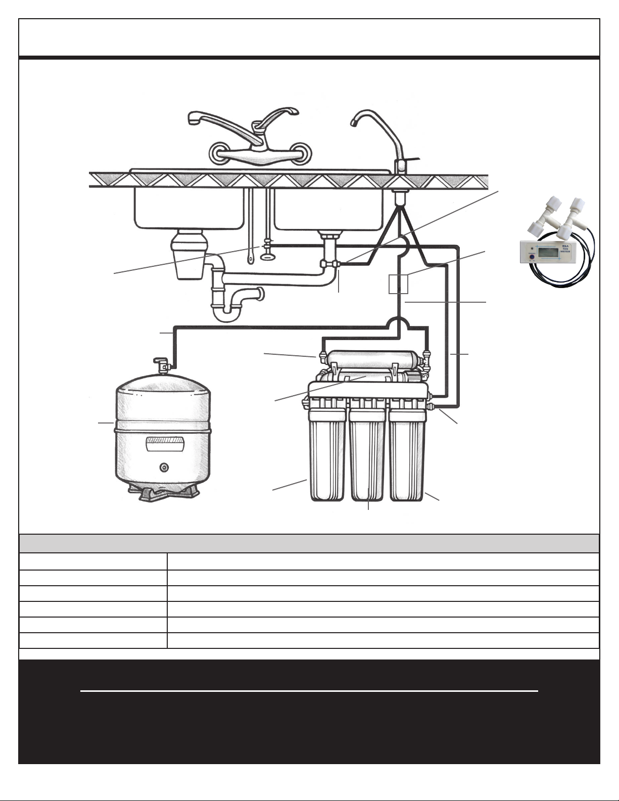
Optional Ice Maker Hook-Up
If your refrigerator is less than 25 feet to your R.O. unit,
1/4” polypropylene plastic tubing is recommended. If your
refrigerator is greater than 25 feet from your R.O. unit,
3/8” tubing is recommended. Do not use copper tubing
as an objectionable ice cube taste can result.
To begin, install a tee in the blue tubing between the nal
lter and the faucet. Next, it is recommended to install
a ball valve in the line to the ice maker. This will allow
storage tank pressure to increase sufciently for the ice
maker solenoid to operate properly. Leave the ball valve
in the closed position until the tank is full after start up
procedure is completed, open ball valve.
Drilling with the recommended Relton cutter
(6)
Drilling the Faucet Hole
The product water faucet may be installed on any at
surface at least 2” in diameter. Check the underside of the
location for interference.
Porcelain/Enamel Sinks
A 1” variable speed drill is recommended for this
procedure. A spring loaded Relton style drill set is strongly
recommended to prevent chipping. The plastic sleeve
supplied on the pilot drill is to be positioned on the drill
bit against the drill chuck. This prevents the chuck from
contacting the porcelain after the pilot hole has been
completed. Avoid high motor RPM during the initial
cutting of the porcelain as this can cause chipping.
Stainless Steel Sink
Make a small indent to mark the desired drilling location
using a center punch. Drill a pilot hole with a 1/8” metal
drill bit. Enlarge the hole using a 1” metal drill bit.
Air Gap Faucet Installation
Once the hole has been drilled place the chrome washer
under the faucet body. Next, insert the rubber gasket under
the chrome washer and locate the RO faucet in the hole.
Install the lock washer and nut and then tighten rmly
while aligning the faucet in the desired direction. Finally,
connect the Easy Fit 3/8” ttings (in the installation kit)
on the faucet shank using teon tape.
Installation - Product Water Faucet
Using a carbide tipped drill bit, drill a pilot hole completely
through the porcelain and the material underneath. Place
the spring loaded porcelain saw into the drill chuck. Make
sure the pilot guide is inserted tightly. Insert the pilot guide
into the pilot hole. Push down gently on the drill motor to
apply light pressure to the porcelain surface. Start the drill
motor turning as slowly as possible. After the initial cut
has started, motor speed may be gradually increased. The
cut may require three to four minutes to complete. Going
faster could result in excessive chipping. This saw is used
to cut the porcelain only. Be sure a complete ring has been
cut through the porcelain to the metal underneath.
Place the nish hole saw into the drill chuck. Make sure
the pilot guide is inserted tightly. Insert the pilot guide
into the pilot hole. Begin cut using a slow speed and light
pressure until the metal has been penetrated.
Optional Ice Maker Hook-Up
If your refrigerator is less than 25 feet to your R.O. unit,
1/4” polypropylene plastic tubing is recommended. If your
refrigerator is greater than 25 feet from your R.O. unit,
3/8” tubing is recommended. Do not use copper tubing
as an objectionable ice cube taste can result.
To begin, install a tee in the blue tubing between the nal
lter and the faucet. Next, it is recommended to install
a ball valve in the line to the ice maker. This will allow
storage tank pressure to increase sufciently for the ice
maker solenoid to operate properly. Leave the ball valve
in the closed position until the tank is full after start up
procedure is completed, open ball valve.
Drilling with the recommended Relton cutter
The Pilot Drill is used to
drill a hole completely
through to provied a guide
for both the Porcelain Saw
and Finish Hole Saw.
The Porcelain Saw is used
to cut though the porcelain
surface only. This saw cuts
a smooth, chip-free, beveled
groove through the porcelain
to the metal base.
The Finish Hole Saw is used
to cut the remaining metal
through to create the hole of
the desired nished size.