Voltea DiUse User manual

DiUse©Owner’s Manual
Installation and Operation

1
All rights reserved. No part of this publication may be reproduced, stored in a database or retrieval
system, published in any form or in any way, electronically, mechanically, by print, photo print, microfilm
or any other means without prior written permission from the manufacturer. All Voltea trademarks and
logos are owned by Voltea B.V. All other brand or product names are trademarks or registered marks of
their respective owners. Because we are continuously improving our products and services, Voltea
reserves the right to change specifications without prior notice. Voltea is an equal opportunity employer.
208M112 DiUse Owner’s Manual: Copyright © 2018
1920 Hutton Court #300
Farmers Branch, TX 75234
469.620.0133
www.voltea.com

2
Contents
1 DiUse Owner’s Manual .............................................................................................................. 4
1.1 General safety precautions ................................................................................................ 4
2 Liability and Warranty ................................................................................................................. 5
2.1 Liability .................................................................................................................................. 5
2.2 Warranty ............................................................................................................................... 6
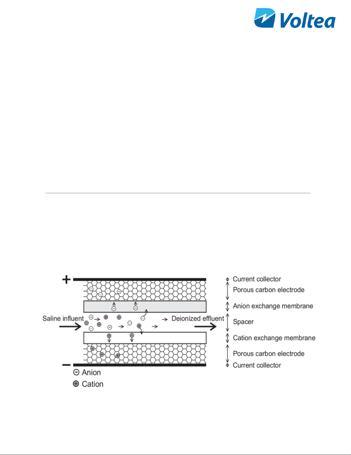
3 Voltea CapDI - Membrane Capacitive Deionization .............................................................. 6
4 DiUse ............................................................................................................................................ 7
4.1 Features ............................................................................................................................... 7
4.2 Specifications ....................................................................................................................... 8
4.3 Feed water quality ............................................................................................................... 9
5 System Overview ...................................................................................................................... 10
6 System Installation .................................................................................................................... 11
6.1 Packing ............................................................................................................................... 11
6.2 Tools and materials .......................................................................................................... 11
6.3 Module installation ............................................................................................................ 11
6.4 Placing leak sensor ........................................................................................................... 14
6.5 Placing the covers. ............................................................................................................ 14
6.6 Water connections ............................................................................................................ 14
6.7 Powering the system up/down ........................................................................................ 14
6.8 Filling the Cleaning In Place (CIP) container ................................................................ 15
6.9 Flushing the module ......................................................................................................... 17
7 System Start Up - Operation ................................................................................................... 18
8 System Control Through LCD ................................................................................................. 18
8.1 DiUse Screen Navigation Chart ...................................................................................... 19
8.2 Voltea DiUse ...................................................................................................................... 19
8.2.1 Process steps ............................................................................................................ 20
8.2.2 Alarms ......................................................................................................................... 21
8.3 Device info ......................................................................................................................... 22
8.4 System ................................................................................................................................ 23
8.5 User functions .................................................................................................................... 24
9 Changing Flow Restrictors ....................................................................................................... 24

3
10 Electrical Conductivity Probe Calibration ........................................................................... 26
11 System Components ............................................................................................................ 30
11.1 Electric cabinet .................................................................................................................. 30
11.2 Valves, switches and pumps ........................................................................................... 30
Appendix ............................................................................................................................................ 31
Flow restrictor color and flow ....................................................................................................... 31
Spare parts list ............................................................................................................................... 31
P&ID ................................................................................................................................................ 32
Process flow diagram ................................................................................................................... 33
DiUse installation PFD ................................................................................................................. 34
Weekly checklist sheet ................................................................................................................. 35

4
1 DIUSE OWNER’S MANUAL
This manual:
• Familiarizes the user with the equipment.
• Explains installation and setup procedures.
• Provides basic programming information.
• Explains the sequential steps of operation.
• Gives specification information.
Read this manual First: Before you operate the DiUse, read this manual to become familiar with the device
Through this manual, special symbols will appear:
NOTE
Is used to emphasize information related with
installation, operation and maintenance without
highlighting any hazard.
WARNING!
Warning is used to indicate a hazard which could
cause injury or death if ignored.
CAUTION!
Caution is used when failure to follow directions could
result in damage to equipment or property.
The CapDI system meets the essential safety and health requirements of the European Union. This means
that the system can be operated and maintained safely if all safety precautions are observed. However,
dangerous situations can occur due to injudicious or negligent use of the CapDI system. If a UL mark is
attached to the system, then it has performed to UL standards and is certified.
1.1 GENERAL SAFETY PRECAUTIONS
The installation, service and maintenance of this equipment should be rendered by a qualified and trained
technician. This manual is written specifically for these individuals and is intended for their use. Untrained
individuals who use this manual assume the risk of any resulting property damage or personal injury.
NOTE: The DiUse system is not intended for use with water of unknown quality.
NOTE: The DiUse system is to be supplied with cold water.
WARNING!
Electrical shock hazard: Located on the electrical
cabinet door and inside the electrical cabinet. The
electrical cabinet may never be opened when the
system is producing water, unless advised to do
so.

5
WARNING!
If incorrectly installed, operated or maintained,
this product can cause severe injury. Those who
install, operate or maintain this product should be
trained in its proper use, warned of its dangers,
and should read the entire manual before
attempting to install, operate or maintain this
product.
CAUTION!
This product is not to be used by children or
persons with reduced physical, sensory or mental
capabilities, or lack of experience or knowledge,
unless they have been given supervision or
instruction.
CAUTION!
If the power cord of the unit looks or becomes
damaged, the cord should be replaced by a Voltea
service engineer or similarly qualified person to
avoid hazard.
Before installing be sure to check all applicable plumbing codes and ordinances. Local codes and
legislation may prohibit the discharge of sanitizing or descaling solution to drain. The system and
installation shall comply with applicable state and local regulation.
The WARNING and CAUTION signs are not meant to cover all possible conditions and situations that may
occur during installation, maintenance and operation. Understand that common sense, caution and careful
attention is always needed.
Always use protective clothing and proper face or eye protection when handling chemicals and tools.
Observe the following general safety precautions:
• Check the proper functioning of the system daily.
• Always replace damaged or defective parts before putting the system into use again.
• Do not make modifications to the system without prior approval of the manufacturer.
• Do not open the electrical cabinet when the system is powered on. unless advised to do so.
• If chemicals are supplied, the attached safety procedures should be observed.
2 LIABILITY AND WARRANTY
2.1 LIABILITY
Voltea will, under no circumstances be held liable for any consequential damages. The recipient hereby
disclaims all representations and warranties, whether expressed or implied with respect to materials and/or
prototypes. Including without limitation any warranties of non-infringement, merchantability or fitness for

6
merchantability or fitness for any particular purpose save that such shall have been prepared with
reasonable skill and care. The recipient accepts all risks which may be inherent in its use of materials
and/or DiUse system and shall hold harmless and indemnify each of Voltea and its affiliates officers,
director, shareholders, employees and agents from and against any and all claims, damage, losses or
other liabilities that may arise directly and solely from recipient’s use, storage, handling or disposal of the
materials and/or systems.
2.2 WARRANTY
CapDI modules supplied with DiUse have been tested and have a guaranteed performance as they have
passed Voltea’s quality control test (a certificate of analysis will be supplied with each module upon
request). Voltea does warrant workmanship (leakage, connections) of the CapDI module for a period of 1
year from shipment provided that the CapDI module is operated within the recommended operational limits
as provided in the section 4.2 and 4.3. Voltea does not warrant desalination and other performance aspects
of the CapDI modules within the customer application. Voltea warrants the DiUse for a period of 1 year
from shipment provided that the system is operated in accordance with this manual.
3 VOLTEA CAPDI -MEMBRANE CAPACITIVE DEIONIZATION
The CapDI system uses Capacitive Deionization technology and its function is the removal of ions from the
water.
NOTE: The CapDI system does not disinfect water.
CapDI:A tunable water deionization technology that is designed to remove dissolved salts from a variety
of water sources ranging from tap water and brackish groundwater to industrial process water. CapDI
achieves this at a lower economic cost and reduced environmental impact than any other available
technology.

7
A CapDI module consists of a housing which contains multiple stacks of parallel unit cells. Each unit cell
consists of two porous carbon electrodes separated from each other by a spacer. On top of the electrodes,
ion exchange membranes are placed. The spacer between the membranes acts as a flow channel to
transport the water to be desalinated.
The water flows through a small electrical field of approximately 1.5 volts that is created over a pair of
electrodes. Dissolved ions are pulled out of the water stream, toward the electrodes. The electrodes are
separated from the water by the membranes that selectively allow only positive or negative ions to pass.
CapDI is effective at removing all type of ions from water (e.g. calcium, sodium, chloride, carbonate).
Uniquely:Our technology is environmentally friendly by its low energy consumption and minimal to no
chemical usage. Thus, allowing any unrecovered water to flow back into the ecosystem safely.
Scalable: Voltea’s technology treats water types ranging from residential consumer appliances to large-
scale industrial plants. Our systems are modular, allowing easy expansion to meet any increased water
demands.
Tunable: CapDI is tunable, allowing adjustable TDS reduction between 25% - 95% depending on customer
needs. Eliminating the requirements for blending to achieve a specific water quality. The customer sets
their desired reduction rate and the CapDI maintains this level, continually adjusting itself to account for
any fluctuations in feed water characteristics.
4 DIUSE
Voltea’s miniaturized version of the CapDI systems, specifically made for the point-of-use applications.
DiUse softens and desalinates brackish water for homes and businesses at an advantage to traditional
desalination technologies due to it being a salt-free, chemical-free alternative. DiUse is ideal for the
HoReCa industry alongside small households.
4.1 FEATURES
• Automated system CIP (Clean-In-Place)
• Voltea’s remote monitoring and control (option)
• Pure outlet conductivity meter (0 – 5 mS/cm)
• Total flow meter (0 – 10 L/min or 0 – 2.6 gpm)
• Built in display

8
4.2 SPECIFICATIONS
Performance
Produced flow rate*
0.3 – 2.2 L/min (0.08 - 0.58 gpm)
Instant flow rate*
0.5 - 4 L/min (0.13 - 1.06 gpm)
Salt removal
25 - 90 %
Water recovery
40 - 90 %
System Specifications
Average power requirements
0.13 kW, Single Phase (110 - 240 V AC / 50 -
60 Hz)
System dimensions (L x W x H)
0.32 x 0.43 x 0. 64 m (1’10’’ x 1’5’’ x 2’1’’)
Power output to modules
0 - 65 A / 0 - 2 V DC
Weight**
17kg (37 lbs.)
Feed inlet coupling
3/8’’ push fit
Product outlet coupling
3/8’’ push fit
Concentrate/Waste outlet coupling
3/8’’ push fit
Operational
Requirements
Water feed pressure
3 - 20 bar (45 - 300 psi) System is equipped
with a pressure reducer.
Water pressure produced***
≤3.5 bar (51 psi)
Operating ambient air temperature
Max < 35 °C (95 °F)
In/Outputs
Start/Stop
Pressure switch (standard) or external signal
(24 V DC)
Operational
Pressure
Setpoints
Start****
≤2.0 bar (28 psi)
End****
≤3.5 bar (51 psi)
Cleaning
Procedure
Automated cleaning with citric acid
Control (auto/manual)
Automatic: on cycles of operation
Storage
1L chemical container

9
Controls
Remote control / Data monitoring
Total flow, average conductivity, average
voltage, cycle counts and alarms (2G SIM
/GSM bit internet or local)
Parameter change
Locally
*Depends on TDS reduction and water recovery
**Weight without module
***Depends on flow target
****Pressure may vary
4.3 FEED WATER QUALITY
Parameter
UNIT
RANGE
Removal limit
Δppm
≤1300
Total dissolved solids (TDS)
ppm
≤2000
Total organic carbon
ppm
< 10
Chemical oxygen demand
ppm
< 20
Turbidity
NTU
< 4
Fats, Oils, Greases
ppm
< 0.5
Total suspended solids (TSS)
ppm
< 4
Free Chlorine
ppm
< 2
pH
2 – 10
Iron total
ppm
< 0.5
Total hardness (CaCO3) *
ppm
< 1000
M Alkalinity (CaCO3) *
ppm
< 1000
Pre – filtration
µm
Supplied separately
Temperature
﮿C / ﮿F
1 - 35 / 34 – 95
Chemicals
Contact Voltea
*Limit depends on set TDS reduction and water recovery
CAUTION!
5-micron filter is the minimum required pretreatment
for the feed water.

10
5 SYSTEM OVERVIEW
Connection
View
LCD Screen
Control Panel
Air Intake
Cleaning Solution Container
Pure Water Outlet Push-In Connector
Feed Water Inlet Push-In Connector
Waste Water Outlet Push-In Connector
Cooling Vent
Power
Control
View

11
6 SYSTEM INSTALLATION
NOTE: Read this section entirely before starting the installation. Follow all applicable plumbing and
electrical instructions.
6.1 PACKING
• The DiUse system is shipped in two boxes.
• One box contains the module and module T-
junction (left picture).
• The other box contains the DiUse system,
power cable and spare flow restrictors.
Modules weigh 23 kg (50.7 lbs.)
6.2 TOOLS AND MATERIALS
• Safety shoes
• 2x size 13 wrenches
• Hex key number 4
• Flathead screwdriver
6.3 MODULE INSTALLATION
• Loosen the connections holding the curved
cover in place.
• Lift off the curved cover being careful of
protruding parts (e.g. air filter).

12
• Remove orange stoppers from module. Add
manifold/T-junction to center of module
using stem adapter.
• Rotate the module so the red terminal is on
the left and the black terminal is on the right,
when facing the water side of the electrical
cabinet.
• Push the module on the frame up against the
stoppers.
Modules weigh 23 kg (50.7 lbs.)
and the system 17 kg (37 lbs.). It is
recommended to wear safety shoes during
installation.
• If done correctly, the module inlet (the
connection that is NOT in the middle of the
module top) will be facing outward from the
system, and the edge of the module will be
in line with the edge of the frame.
• The vertical tube that is attached to a T-
junction should be pushed into the module
outlet. If placed correctly, pulling on the tube
firmly should not disconnect it from the
module.
• The tubing that comes from the waste line
(above the center of the module) should be
pushed into the vertical connection coming
from this point.
Module
Manifold
Electrical
terminals

13
• Each module has one red and one black
electrical terminal, with each terminal having
two M8 nuts. Unscrew one of the nuts from
the red terminal. Place the red cable from
the system on the red electrical terminal,
then screw the nut back on. Tighten using
two size 13 wrenches, one on the top nut
and one on bottom nut. Repeat the process
with the black terminal and black cable. Be
sure the bottom nut is not sitting on the
plastic bushing.
Plastic bushing

14
6.4 PLACING LEAK SENSOR
The leak sensors are pre-installed. If the leak
sensors were removed during transit:
• Take the two sensors and place them in the
clamps as shown in the image. The tip of the
sensor should be in contact with the leak
tray.
NOTE: Leak tray should always be dry to avoid
triggering the leakage alarm and stopping the
system.
NOTE: You can remove the leak sensors before
installing the module and re-install them right after.
6.5 PLACING THE COVERS.
Place the covers back and tighten the connections holding the covers in place.
NOTE: Every connection has a spacer attached to it. Spacers should be between the covers and frame
before tightening.
6.6 WATER CONNECTIONS
Size 3/8” tubing should be used to connect the inlet to the IN connection on the side of the unit. The purified
(Out) water is discharged through the top 3/8’’ connection. Concentrate (Waste) is discharged through the
bottom 3/8’’ connection.
Connections are indicated by stickers.
6.7 POWERING THE SYSTEM UP/DOWN
• A power cable is provided with the system.
• Connect the cable to the power connection
on side of the unit.
• Ipowers ON the system and Opowers
OFF.

15
NOTE: DiUse systems are specific to either 110 V
or 240 V. If in doubt about system specifications,
please contact Voltea.
6.8 FILLING THE CLEANING IN PLACE (CIP)CONTAINER
• Unscrew the lid of the CIP container.
WARNING!
Acid may splash. Avoid
contact with eyes.
CAUTION!
If using citric acid
powder always use
distilled or sterile water
for CIP solution
preparation.
• Fill container to max volume with 50% w/w
citric acid solution. The maximum and
minimum levels are indicated by stickers
• Screw the lid of the CIP container back on.
• Go to CIP L.LEVEL in alarms and press
ENTER, the alarm now reads CIP L.LEVEL
: FUL

16
NOTE: CIP solution level is calculated based on the CIP’s pump capacity to exhaust the 1L of CIP solution.
For this reason, it is mandatory to reset the CIP alarm once the CIP bottle is refilled. Around 36 ml of CIP
solution is used per CIP event.
When filling the CIP container for the first time, the CIP line needs to be primed.
• Disconnect the CIP line check valve.
Check valve

17
• Use a small beaker to collect the acid during
priming.
• Through the main controls go to RELAY TEST
and open the CIP Pump (CIP) by pressing
ENTER. The CIP solution will start flowing
through the CIP line. Once the solution
reaches the beaker, stop the CIP pump by
pressing ESC. Reconnect the check valve.
The CIP line is now primed.
6.9 FLUSHING THE MODULE
Before normal operation the modules should be flushed for a minimum of 15 minutes. Module flush is a
build in process, please refer to chapter 8.5.

18
7 SYSTEM START UP -OPERATION
Power the system up. Using the buttons on the LCD screen, press ENTER to go from Voltea DiUse to
IDLE-START. Press ENTER again to start operation.
NOTE: It may take up to 8 operational cycles for the unit to adjust and output water of the desired quality.
NOTE: If the system is not reaching target pure conductivity, a flow restrictor change may be necessary.
Voltea or a trained reseller can assist with choosing the best option for the specific conditions.
When operating for the first time, it is advised to fill the tank while the connection to the application (2) is
closed, this can take several minutes depending on the pure flow rate. The inlet valve (1) should remain
open. When the tank is full, and system is in WAIT mode you can open valve 2.
8 SYSTEM CONTROL THROUGH LCD
The system can be controlled using the LCD screen
and the keypad. Navigate through the screens using
the UP and DOWN buttons, confirm selection with
ENTER, and return to the previous screen by
pressing ESC.
NOTE: If the screen is blank, unresponsive or
flickering for more than 2 seconds, please contact
Voltea.
1
2

19
8.1 DIUSE SCREEN NAVIGATION CHART
The flow chart gives an overview of the DiUse functions and parameters that can be controlled through the
LCD.
NOTE: The password is available to authorized dealers.
8.2 VOLTEA DIUSE
Voltea DiUse Branch
IDLE/ENTER
IDLE/ENTER
100 uS/cm
• This is the initial screen appearing after
powering up. System is in IDLE, activate the
system by pressing ENTER.
• Average conductivity of the last 5 cycles is
also presented.
OPERATION/
CLEANING
OPERATION
100 uS/cm
• The system is operating and cycling
through the process steps.
• Average conductivity of the last 5 cycles
is also presented.
Other manuals for DiUse
1
Table of contents
Other Voltea Water Filtration System manuals
Popular Water Filtration System manuals by other brands

National Flooring Equipment
National Flooring Equipment DLS3000 instruction manual

TotalPond
TotalPond 52231 instruction manual

Air Water Life
Air Water Life AQUA-IONIZER DELUXE 7.5 owner's manual

PureEffect
PureEffect ULTRA-WHW installation instructions

Dongtuo
Dongtuo KC-88 manual

Graco
Graco 210-091 Instructions-parts list