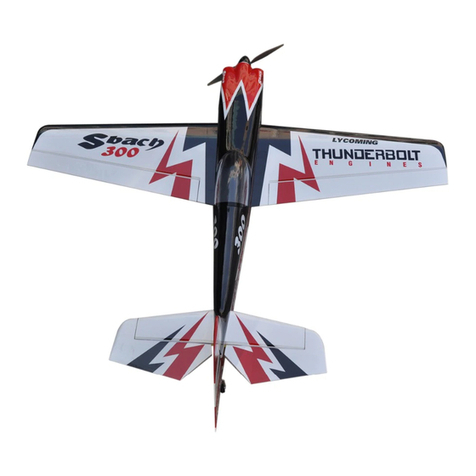
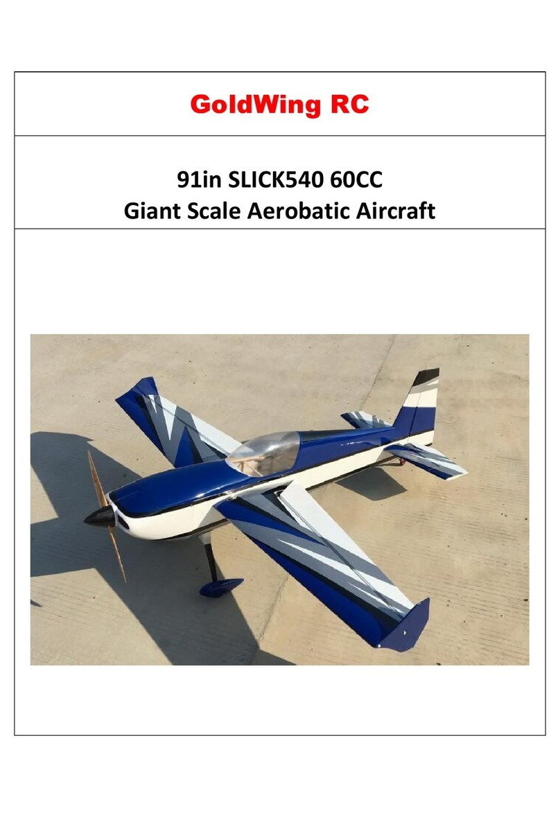
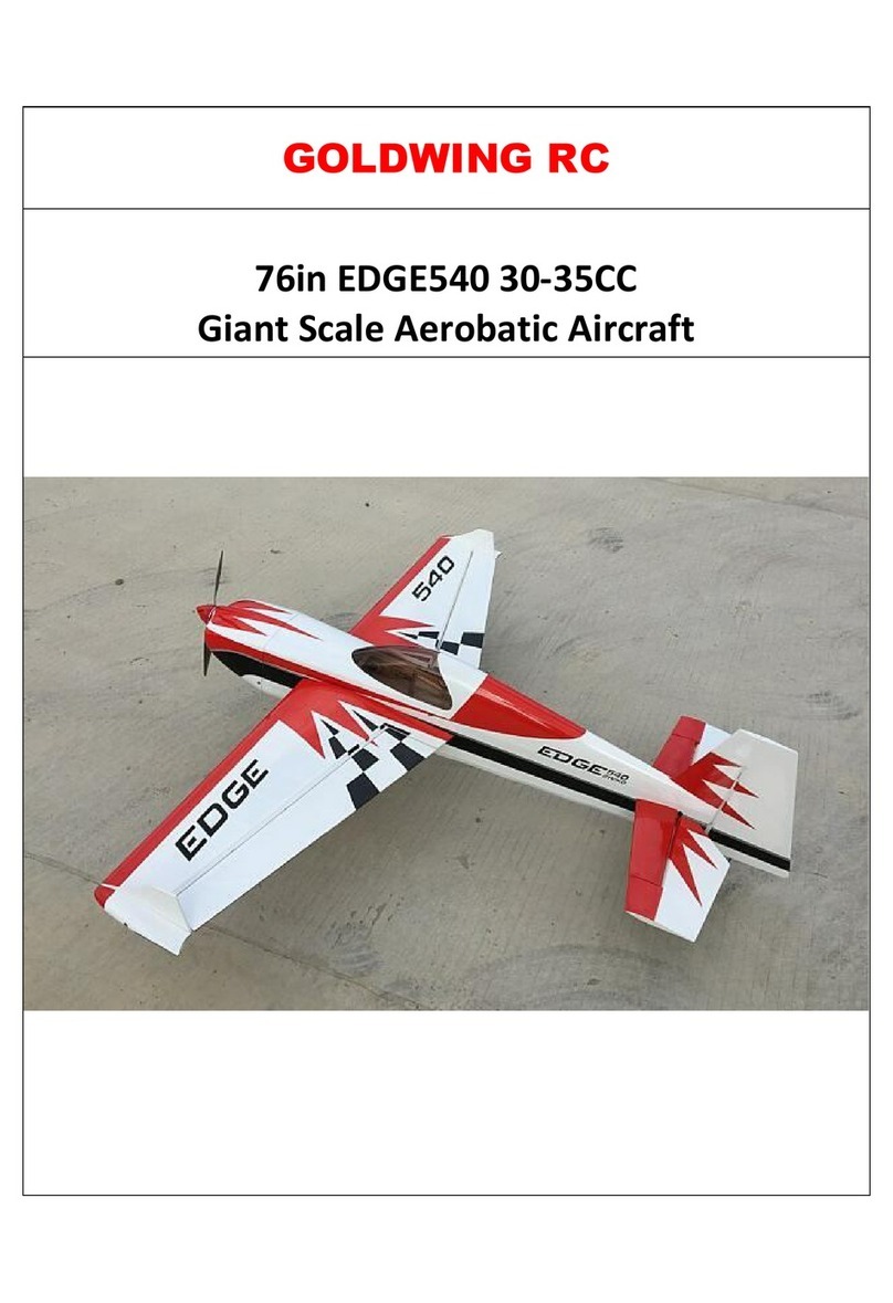
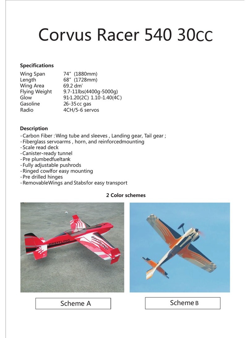
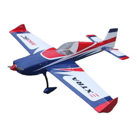
Goldwing CORVUS RACER EDGE540 User manual

Goldwingrc is located in the centre of the model plane manufacturing community, the
beautiful coastal city of ZHUHAI, near Hong Kong and close to Macao.
Our general manager ,Paul, who has flown models for 15 years, has won the much
coveted 3D Championship of China, assuring you quality and design of GW products.
GW has a working facility of over 4000sq.Ft. With up-to-date equipment producing an
assortment of R/C model airplanes. Annual average production ranges from 20,000 to
30,000 pcs .Our current focus areas are electric and gasoline aircraft with specialist
accessories. The superior quality and 3D performance of these planes are highly
praised by our American ,European and Japanese customers.
We hope to establish long-term business relationships with friends from around the
world on the basis of mutual equality and benefit.
WWW.GOLDWINGRC.COM
Address: No.19, Western Jinfeng Rd,
Jinding science and technology
Zone, Zhuhai ,China
Postcode: 519028
Tel: 86-756-6123059
Fax: 86-756-6123306
Info email: mfg@goldwingrc.com
sales@goldwingrc.com
Sales1@gwplane.com
1642378762@qq.com
100CC V3 SERIES
ASSEMBLY MANUAL
WWW.GOLDWINGRC.COM
YAK54/SUKHOI SU26M/SUKHOI SU29/MXS/SBACH342
CORVUS RACER EDGE540/EXTRA260/EXTRA330SC/YAK55M/YAK55SP

01
Thank you for purchasing this excellent almost-ready to fly R/C model!!! This ARF adopts the
latest 3Ddesign features and emphasizes high performance,light weight and fun.This plane is
designed by professional engineers and built by skilled craftsmen.Many of the parts are already
pre-installed for you! We wish you great success in the assembly and flying of your new model.
Features:
1. Latest structure
2. Super quality
3. Easy installation
4. Carbon fiber wing tube
5. Carbon fiber tail wheel assembly
6.Two pieces removable wings and stabs
7.Extra strength epoxy control Horns
8.Adjustable pushrods for easy fine tuning
9.One piece carbon fiber landing gear
10.Advanced rubber wheels
11.Long servo arms included
12.Servo extension safety connector clips also included
13.Scale canopy and latest nilon bolts
14. Fixed ring inside cowling for easy build
16. Pre-hinged control surfaces ready to fly
17. Pre-installed servo wire tube
18. Pre-mounted and plumbed gasoline tank ready to fly
19. Genuine ORACOVER film
20. Special 4.5in fiber spinner in SBACH300 and SBACH 342 included
21.Low wing loading makes it easy to fly
22.Light weight construction with high structural strength
23.Excellent aerobatics and 3D performance
If you have any problems and questions please contact GoldwingRC:
Address: No.19, Western Jinfeng Rd, Jinding science and technology
Zone, Zhuhai ,China
Postcode:519028
Tel:86-756-6123059
Fax:86-756-6123306
Info email: mfg@goldwingrc.com sales@goldwingrc.com
1642678762 .
15.Removable rudder with awire
@qq com
INTRODUCTION
sales1@gwplane.com

Attention
1.You should not regard this plane as toy!
2.Before the assembly please the careful reading instruction booklet, he can give you the full
detail instruction if you are the first contact airplane model public figure, should assemble
under the experienced correct instruction!
3.Please inspect in the packing all components, if lacks perhaps the damage, please
immediately with dealer relation.
4.As a result of weather temperature the moist change, the model outer covering possibly can
appear the phenomenon which relaxes, you may use the package to have a cotton fabric the iron
to burn again the outer covering smoothly, but must take care not to apply too much heat to one
area for long periods of time.
5.Inventory and inspect all parts and hardware for any imperfections or damage. Contact us
quickly if there are missing or damaged parts.
6.Fly only in AMA (Academy of Model Aeronautics) approved areas.
7.The manufacturer can not control the assembly, operation and maintenance of this product
therefore, We are not responsible for any damage that occurs as a result of the use or misuse of
this radio controlled model.
8.All GOLDWING products are guaranteed against defects within 30 days of receiving your
airplane. This warranty is limited to construction or production defects in both material and
workmanship. It does not cover any components or parts damaged by misuse or modification.
9.The purchaser accepts all responsibility of any and all structural or mechanical failures.
10.GoldWingRC reserves the right to make changes and amendments to construction manuals,
terms and conditions without notice.
108"(2740mm)
104.5"(2650mm)
2117sq.in(136.6sq.dm.)
25.3-28lbs(11500-12800g)
Wing Span:
Wing Span:
Wing Span:
Length:
Length:
Length:
Wing Area:
Wing Area:
Wing Area:
Weight:
Weight:
Weight:
Corvus Racer Edge540
108"(2740mm)
104.5"(2650mm)
2104sq.in.(135.8sq.dm.)
25.3-28lbs(11500-12800g)
Extra260
108"(2740mm)
104.5"(2650mm)
2114sq.in(136.4sq.dm.)
25.3-28lbs(11500-12800g)
Extra330SC
106"(2690mm)
102"(2590mm)
2108sq.in(136sq.dm.)
25.3-28lbs(11500-12800g)
Yak55M
107"(2720mm)
103.5"(2630mm)
2105sq.in.(135.8sq.dm.) 2111sq.in.(136.2sq.dm.) 2108sq.in.(136sq.dm.) 2102sq.in.(135.6sq.dm.)
25.3-28lbs(11500-12800g)
Yak54
107"(2720mm) 108"(2740mm) 107"(2690mm)
102"(2590mm) 104.5"(2650mm) 102"(2590mm)
25.3-28lbs(11500-12800g) 25.3-28lbs(11500-12800g) 25.3-28lbs(11500-12800g)
Sukhoi Su26M Sukhoi Su29 MXS
Flying
Flying
Flying
108"(2740mm)
104.5"(2650mm)
2111sq.in(136.2sq.dm.)
25.3-28lbs(11500-12800g)
2103sq.in.(135.7sq.dm.)
107"(2690mm)
102"(2590mm)
25.3-28lbs(11500-12800g)
Sbach342
YAK55SP
02

Introduction --------------------------------------------------------------------
Attention------------------------------------------------------------------------
Wing Assembly-----------------------------------------------------------------
Aileron Control Horns --------------------------------------------------------
Aileron Servo Installation ----------------------------------------------------
ElevatorAssembly -------------------------------------------------------------
Elevator Servo Installation ---------------------------------------------------
Stap Tube Installation ---------------------------------------------------------
RudderAssembly --------------------------------------------------------------
Rudder Horns and Hinges ----------------------------------------------------
Rudder Servo Installation -----------------------------------------------------
Tail Wheel Installation --------------------------------------------------------
Main Landing GearAssembly -----------------------------------------------
Landing Gear Installation ----------------------------------------------------
Pants Installation --------------------------------------------------------------
Engine Installation ------------------------------------------------------------
Firewall Assembly -------------------------------------------------------------
Engine Assembly --------------------------------------------------------------
Throttle Servo Installtion ----------------------------------------------------
Muffler Assembly -------------------------------------------------------------
Hatch And Fuel Tank Ignition Module ---------------------------------------
Ignition and battery assembly ------------------------------------------------
Cowl Assembly -----------------------------------------------------------------
Flight Preparation -------------------------------------------------------------
Wing Final assembly ----------------------------------------------------------
Canopy assembly --------------------------------------------------------------
Symmetry Control ------------------------------------------------------------
Control Throws ----------------------------------------------------------------
C.G Location -------------------------------------------------------------------
Engine Debugging -------------------------------------------------------------
ACCESSORIES LIST --------------------------------------------------------
NEW PRODUCT -------------------------------------------------------------
100CC SERIES PLANE -----------------------------------------------------
01
02
04
04
05
06
06
08
09
10
11
13
14
15
16
17
17
18
19
20
22
23
24
25
25
26
26
27
27
27
28
32
33
TABLE OF CONTENTS
03

04
1.Scuff the horns with sand paper to
ensure a good glue bond.
3.Apply 30 minute epoxy inside the
pre-cut slots and coat the horns with
epoxy , Insert them into the pre-cut
slots. Wipe away excess glue with
rubbing alcohol.
2
Aileron Control Horns
1
3
Wing Assembly
2.Pre-hinged control surface is
ready to fly.Remove the covering
below to expose the pre-cut slots with a
knife. .

05
Aileron Servo Installation
2.The covering of the servo location
had been remove as shown.Put the end
of the servo extension in the servo
location.And then pull the extension
lead through to the root of the
wing.Taping servo lead to the inside
of the wing panel will help to
prevent lead from dropping back
inside of wing panel during
transportation.
4.Mount the servo arm and the
extension arm with M2*8mm screws
and locking nuts as shown.Then turn on
the transmitter and plug the servo into
receiver. Ensure the channel is neutral.
Install the servo arm facing toward the
wing tip.Position the servo arm 90
degrees to the servo.
1.Use the provided safety clips to
secure the servo and servo extension
leads.
3.Drill 1mm holes for the servo
mounting screws. Position the servo
with the servo label closest to the wing
trailing edge. Use a drop of thick CA
glue on each screws to prevent tapping
scr e w s fr o m lo o s ening due to
vibration. Install servo with M2*12mm
tapping screws.
Minimum Required Servo:180 in.oz / Metal Gear / Digital
M2*8mm screw
44
1
Serbo extension safety
Connector clip
2
Taping
3
Close to the
wing trailing
CA glue
1mm bit

06
6. Repeat all the previous steps for the other servo and wing.
Elevator Assembly
5. Install the arm pushrod and adjust the pushrod length to ensure the aileron
and servo are in the neutral position.
Epoxy horn
3mm latest nylon
ball link assembly
Anodized
AL
Long servo arm
3X60mm
Stainless steel
Adjustable pushrod
5
6

07
3.Position the servo with the servo wire
to the wire pre-slot. Drill 1mm holes
for the servo mounting screws using the
long aiguille.
4.Install servo with M2*12mm servo
mounting screws. Use a drop of thick
CA glue on each screw to prevent
scr e ws fr om lo osenin g due to
vibration.
3
The serbo label
facing the hinge
2
1.Pre-hinged control surface is
ready to fly.Remove the covering
below to expose the pre-cut slots with a
knife. .
2.Scuff the horns with sand paper to
ensure a good glue bond.Install the two
horns with M3*16mm screw and
locking nut. Apply 30 minute epoxy
inside the pre-cut slots and coat the
horns with epoxy, Insert them into the
pre-cut slots.
2
Minimum Required Servo:180 in.oz / Metal Gear / Digital
Elevator servo installation
34
1

08
1.Use the provided safety clips to
secure the servo and servo extension
leads.
Stab Tube Installation
Repeat all the previous steps for the other elevator.
3mm latest nylon
ball link assembly
Epoxy horn
Anodized
AL
Long servo arm
5.Turn on the transmitter. Make sure
the servo is in the neutral position.
Install the servo arm. Position the servo
arm 90 degrees to the servo,and tighten
the arm screw.
5
6.Install the arm pushrod with
M3*16mm screws. Adjust the pushrod
length so that the servo and elevator are
both in the neutral position.
6
1

4.Install the stab with M3*12mm
screws. Secure the screws with Blue
Loctite.
5.Repeat the previous steps for the
remaining stabilizer.
M3*12mm Screw
4
Rudder Assembly
3.Slide the stab tubes in the fuse stab tube sleeves.
2.Run the extension lead through the fuselage to the receiver.
21
.
31
.
31
.32
.
09
Pre-installed
In this location
21
.
21
.
Pre-installed servo wire tube
22
.
Pre-installed servo wire tube

Rudder Horns and Hinges
1.Remove the covering below to
expose the pre-cut slots with a knife.
2. Scuff the middle of horns with sand
paper to ensure a good glue bond.
Apply 30 minute epoxy inside the pre-
cut slots.
2
1
3.Coat the horns with epoxy. Insert
them into the pre-cut slots. Install the
ball link with M3*16mm screws and
locking nuts.Tightening the nuts is
recommended.Wipe away excess
glue with rubbing alcohol.Make
sure the horns are correctly aligned
and symmetry before the apoxy has
cured.
3
4
Tape
4.Keep the hinge holes in a
line.Tape the rudder balance tab to the
top leading edge and the other location
of the vertical fin in the neutral
position as shown.
10

11
Rudder Servo Installation
The rudder cables and couplers have been pre-installed.
1. Drill 1mm holes for the M2*12mm
tapping screws. Fit the servos as shown
with the servo label facing the
rudder.Turn on the transmitter.And
then install AL long arm on the
servo,position the servo arm 90
degrees to the servo.
Minimum Required Servo:180 in.oz / Metal Gear / Digital
1
The servo label facing the rudder
L
Ф1.6*420mm steel wire
5
5.Fit the rudder by aligning the hinges
and inserting the hinge pin from the
bottom of the rudder .The length of
the hinge pin is enough to prevent
the falling after the installation of
the wheel tail.
Crimp
Pre-installed
3mm ball link
Pull -pull
Connector
Wire Cable
2
3mm bit
2mm bit
Double-sided tape
12
34
2.Drill 3mm holes in the AL long arm
for installing 3mm ball links and
screws.Drill 2mm holes in the servo
arm and mount it with 2*8mm
screws and nuts.

12
L
L3
3.Mount the pushrod into the ball links
and adjust the pushrod length same to
the length of servo arm gear.
4.Mount the pre-installed bolt link to
the servo arm with the M3*16mm
screws and the locking nuts.
4
5.Remove any slack in the cables and
crimp to secure. Crimp the brass swage
tu b e w i t h a cr imp i n g tool or
pliers.Finally you can adjust the
cable by loosening or tightening the
cable connectors.
5
3mm latest
link assembly
Nylon ball

13
1.Drill a 6mm hole and fit the steering
ball link.
2.Scuffing the ball link with sand
paper to ensure agood glue bond is
suggestted before gluing.Make sure
the ball link hole is parallel to the
rudder. Apply 30 minute epoxy inside
the 6mm hole and coat the hinges with
epoxy , Insert the ball link into the
hole.
3.Install the tail wheel with 8mm
lo c k ing n u t s and t h r ee w h e el
collars.All wheel collars should be
secured with Blue Loctite.
6mm bit
1
2
Tail Wheel Installation
3

14
Main Landing Gear Installation
5.Insert the 2*225mm steel wire into the rudder steering ball link.Tighten the
set nut.
? 1.7*3 0 0 m m
steel wire
§¶1.5*420m m
steel wire
3mm ball link
Three M3*
12mm screws
Removeable
Rudder with
awire
5
4
M3*12mm screws
4.Remove the cover of the pre-
holes.And mount the wheel tail
with three M3*12mm screws.

15
NOTE: the correct edge in mounting
Straight edge to
Front of fuse
1.Install the landing gear in the pre
drilled holes with the supplied
M4*25mm screws and locking nuts.
Don’t over tighten and crack the carbon
fiber.
2.Remove the covering below to
expose the holes with a knife and
reinstall the landing gear hatch cover.
Secure the M3*20mm screws with Blue
Loctite.The hatch cover maybe not
included in some planes.
3.Tighten the locking nut against the
landing gear strut.(for other planes)
M4*25 socket head
Screw and lock nuts
......4
1
2
Landing Gear Installation
Align axle bolt with front of gear
3

16
4.Install the inner wheel collar on the axle. screw and tighten the wheel collar
in place. Adjust wheel collars in or out until wheel turns freely.
5.Repeat above steps for other wheel
and wheel pant.Final landing gear
installation shown below.
Pants Installation 1(For YAK series)
Pants Installation 2 (For other series)
M3*20mm
Screw and lock
2
Nut
Ф5Axle and
Wheel collar 4 1
.. 42
..
Ф5.1mm
Wheel collar
5
The hatch cover maybe not included in some planes

17
Firewall Assembly
Engine Installation
Not included in the engine
DLE 111 engine(not included)
11
.12
.
12
.
1.Scuff the firewall with grater to ensure easier assembly and epoxy it.
1.Install the inner wheel collar on the
axle. screw and tighten the wheel collar
in place. Adjust wheel collars in or out
until wheel turns freely.
2.And then install the wheel pant
with two M3*12mm screws.
2
11
.

18
Engine Assembly
2.Use a6mm bit to drill the engine mounting holes in firewall.Using
M6*45mm mounting bolts,lock nuts and flat fender washers mount engine
to firewall. Tighten the lock nuts to prevent crushing of the firewall.
3.You can remove engine box top hatch cover for easier installation.
M6 flat fender washers
22
.
2
3.
.
31
1
1.There are two pieces of wooden
t e m p l a t e s s u p p l i e d , o n e f o r
DA100,3W 106ccd and DLE111
gasoline engine,the other one for ZDZ
100B2NG engine. Select the right
template for your engine to mark the
location of mounting holes. If other
engines are used the Universal template
may be modified for any mounting
pattern.
6mm bit 21
.
22
.
2.Install the firewall with the angle aluminum,screws and lock nuts.
21
.

19
3.Distance from front of firewall to front of engine prop hub should be
proper.Use wood washers to achieve correct distance.r It allows for better
shock absorption if you mount the engine with the rubber washer.
Throttle Servo Installation
1.Position the hole and use a 6mm bit to
drill a pushrod exit hole in the firewall
in line with the engine carburetor
throttle arm.
2.Assemble ball link to threaded end of
pushrod.Thread ball link half way onto
pushrod to allow for proper adjustment
during final installation.
3. Mark the cut location for the throttle pushrod and remove pushrod from
throttle arm on carburetor and cut throttle pushrod to length.. Use a L bend to
connect the push rod to the servo arm.
6mm bit
1
Thread ball link half
Way onto pushrod 2
2
"L"shape 3.
The location
Of cutting 1
3.
1
3.Rubber washer
2
3.
(Not included)
This manual suits for next models
9
Table of contents
Other Goldwing Toy manuals

Goldwing
Goldwing EXTRA330SC User manual

Goldwing
Goldwing 91in SLICK540 60CC User manual

Goldwing
Goldwing SBACH User manual

Goldwing
Goldwing PITTS 30CC V3 User manual

Goldwing
Goldwing 50CC V3 SERIES SBACH300 User manual

Goldwing
Goldwing YAK 55M 70 E User manual

Goldwing
Goldwing 76in EDGE540 30-35CC User manual

Goldwing
Goldwing Corvus Racer 540 30CC User manual