Goldwing YAK 55M 70 E User manual

ARF® MODEL
60in YAK55M 70 Electric
Electric Extreme Series
Instruction Manual

ARF® MODEL
Dear Customer,
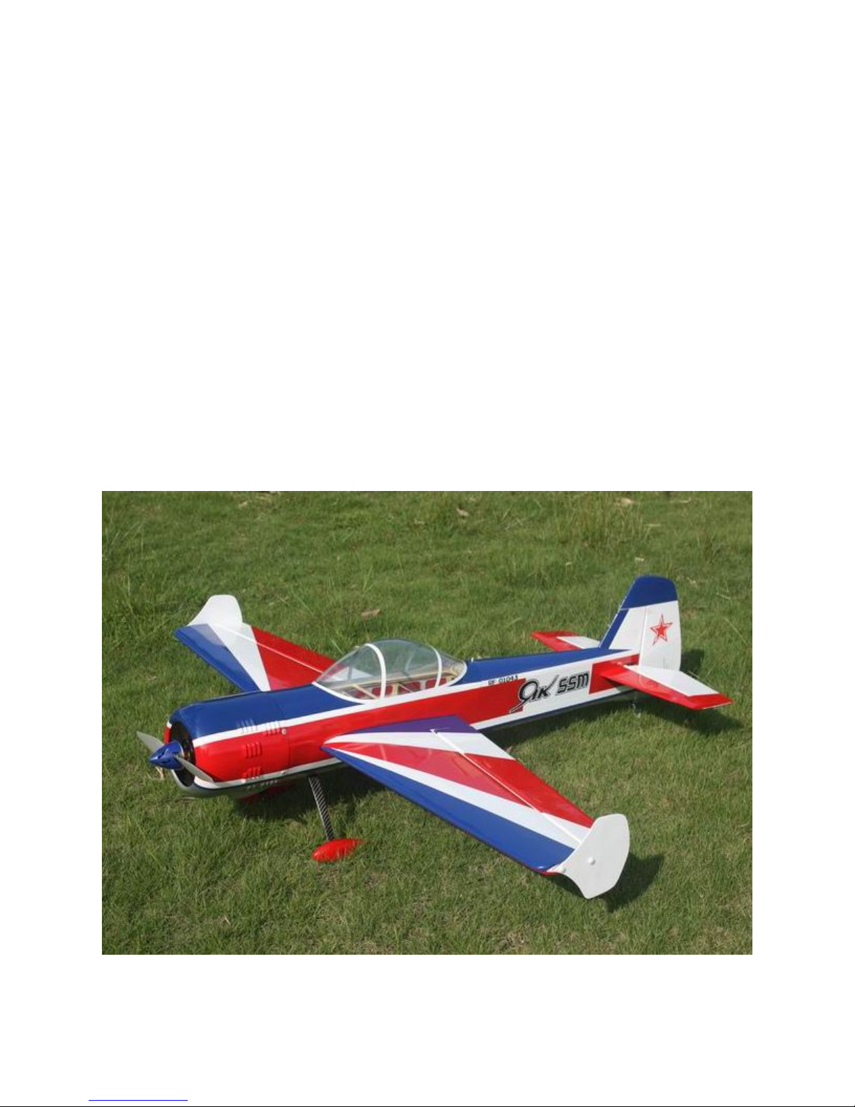
Thanks for purchasing this newly designed 60in YAK55M 70E aerobatic RC airplane. With an
approximate flying weight of 5.5 Lbs., the new 60in YAK55M was designed for IMAC and free style
flying. It was developed with unique appearance and extreme flight performance in mind. The new
60in YAK55M was covered with genuine Monocote film, and equipped with good quality accessories,
including carbon fiber wing tube, carbon fiber landing gear.Also including KUZA Alloy Backplate
Hollowed-out Electric Spinner We hope you enjoy this plane as much as we do.
SAFETY ISSUES OF RADIO CONTROL FLYING MODELS
With radio control aircraft, like any hobby or sport, there are certain risks. The operator of these
models is responsible for these risks. If misused or abused, you may cause serious bodily injury and/or
damage to property. With this in mind, you will want to be certain that you build your model carefully
and correctly. If you are not an experienced flier, have your work checked and ask for help in learning
to fly safely. This model aircraft is NOT a toy and must be operated and flown in a safe manner at all
times. Always perform a pre-flight check of the model including all control surfaces, proper function
of the radio gear, structure, radio range, and any other area relating to the safe operation of this aircraft.
Models are not insurable but operators are. You can obtain coverage through membership in the
Academy of Model Aeronautics (AMA). For an AMA information package call 1-800-435-9262, ext.
292 or visit the AMA website at "www.modelaircraft.org"
By the act of using the final assembled model, the purchaser/operator accepts all resulting liability
ARF MODELS WARRANTY AND RETURN POLICY
We guarantee that the plane is in perfect condition at purchase. The warranty will be voided after
modifications and usages. If you have any questions or find any issues, please contact the distributors
in your area.
Specifications and Recommended Power Setup
Wingspan: 60"(1520mm)
Length: 60"(1520mm)

ARF® MODEL
Wing Area: 725sq in (46.8sq dm)
Flying Weight: 5-6 lbs. (2250-2700g)
Electric Power Setup:
KUZA EXM4120 KV750 4S 3700-4400mAh, 15x8prop
KUZA EXM4120 KV500 6S 3300-3700mAh, 15x8prop
DUSKY XM5050EA-9 6S 3300-3700mAh, 15x8prop
or other 1100-1300 watt, 300g class electric motors
ESC:70-100A
4 Mini size high torque servos, Hitec HS5245 or 7245 recommended
Aircraft radio and receive of your choice, 4 channels minimum
Features and Photo Gallery
Newly designed structure
Aerofoil tail wings
Two pieces removable wings
PVC canopy
Larger ailerons and elevator designed for extreme 3D aerobatic flying
Air exit opeing for cooling
Side Force Generator’s (SFG) Included

ARF® MODEL
Quick release canopy latch
Servo extension safety connector clips
High performance cap head screws

ARF® MODEL
High quality 2mm ball links assembly
New fiberglass horn assembly
Light Electric C.F.Tail wheel assembly
High-quality durable rubber wheels

ARF® MODEL
Improved new Axle (the material of Axle is stainless steel )
Carbon fiber landing gear
Increased diameter carbon fiber wing tube over previous versions
Strengthened fuselage by carbon fiber board and rods
KUZA Alloy Backplate Hollowed-out Electric Spinner included

ARF® MODEL
Honeycomb Board carton packing for safer transportation
Scheme A White/red/blue

ARF® MODEL
Scheme B Yellow/ black/red
Items Required to Complete This Model
1000-1200 Watt, 300g class electric motor
70-100A ESC
4 or 5 mini size high torque servos (Hitec HS5245 or HS 7245)
*1 or 2 servos for elevators

ARF® MODEL
Appropriate servo arms
Servo wire extensions. two 6”, two 12”
Appropriate Lipo batteries (6S 2600-3300mah)
Receiver of your choice (minimum 4 channels)
RC radio of your choice
Shop Supplies/Tools
Covering Iron and heat gun
Hobby tools such as screwdrivers, hobby knife, drill and drill bits, piers, etc.
Thick and Thin CA adhesives
30 minute Epoxy
Isopropyl alcohol
Ruler or tape measure
Blue thread-lock or equivalent
Adhesive backed Velcro and Velcro strap for battery retention
Note: please read all the instructions before you begin construction. Handle the parts of this kit with
care so you do not damage any of the structure or covering. Inspect all the parts for any shipping
damage and report any issues to as soon as you can. Make sure you have a flat and sturdy workbench
and follow all safety advice for the tools and adhesives you plan to use.
Aircraft Covering
Varying temperatures and storage delays can cause covering material to loosen over time and
transportation. We recommend lightly going over all the covering with a covering iron set at
medium temperatures. Be sure to use a soft cover over your iron so you do not scratch the covering
surface. Be sure you go over all seams and edges of the covering to assure it is secure to the airframe
and other covering. Be careful not to apply too much heat or you may cause bubbles or damage to the
covering. A heat gun may also be used along with a soft cotton cloth to shrink and adhere the
covering. Again, be extremely careful when using a heat gun.

ARF® MODEL
Some modellers prefer to seal the hinge gaps using strips of appropriate covering or clear trim tape.
We have found this to be helpful with models intended for higher speed flight or models with unusually
large hinge gaps. Aircrafts that utilize a very tight double beveled hinge line and do not normally
require this step. Sealing the hinge gaps is therefore left as an option formodellers.
Please verify the accessories before assemble:
4 fiber glass servo horns(Bag No. KA07NA1A): 2 horns for ailerons, 1 for elevator, and 1 for
rudder.
*There is a layer of protection film on the horns. Please remove the film before installation.
Pushrods kits: Three 2x65mm pushrods for ailerons & elevator. One 2x85mm pushrods for
rudder.

ARF® MODEL
Ball links (Bag No. KAG0011): 8 PCS
4 Servo extension safety connector clips(Bag No. KAG0019)
Main rubber wheels(Bag No. KAG0146):2 Pcs

ARF® MODEL
Stainless steel Axle kits (Bag No. KA07NH)
C.F Tail wheel assembly (Bag No. KAG0101)
Side force generators (mounted with four M3X18 hand bolts and 2 wood sheets)
2.5"(63mm) CNC Alloy Backplate Hollowed-out Spinner (Bag No. KAG0203)

ARF® MODEL
4 (3x16mm) hex-head bolts & Washers for landing gear mounting
Screews & Washers for cowl: 4(2.5x12mm) Hexagon socket screws & 4 PTFE Washers
Motor mounting hardware set

ARF® MODEL
3 Hex keys
Construction
1. Wing Assembly
1.1 Locate two wing panels with ailerons, and two set of control horns and base plates.
1.2 Locate the slot for control horn on aileron, remove the covering over the slot with heated
soldering iron or sharp hobby knife, and make sure you do it on the bottom side of the aileron.
Insert control horn into base plate then into the slot, trace the edge of base plate with hobby
knife then remove the underlying covering.
1.3 Use some fine sandpaper to roughen up the root of control horn where will be glued into the
slot.

ARF® MODEL
1.4 Fill the slot and coat the root of control horn and the bottom of base plate with 30 minute epoxy,
insert the horn into the slot, press it down firmly. Wipe off excessive epoxy with alcohol wipes.
Set aside until cured.
1.5 The slots for CA hinges are pre-cut. Insert CA hinges half way into the hinge slots on aileron,
apply a drop of thin CA to secure the hinges. Then insert all hinges into slots on the wing at
once, align aileron with the wing, move the aileron up and down a few times to reach the
minimal hinge gap while still allowing full deflection of the aileron. When satisfied, apply
more think CA on both top and bottom sides of each hinges.
1.6 Cut the covering from the aileron servo slots from corner to corner and iron down inside the
openings. Connect servo wire extensions to your servos and secure the connections with the
supplied clips. Feed the servo wires into the wing and out the root. The screw holes for servo

ARF® MODEL
mounting are laser pre-drilled, it is advisable to apply some thin CA to strengthen them, Install
the servos and screw firmly in place.
1.7 Use your radio to set the centers of each servo and then assemble and adjust the length of each
control rod, KUZA 1” aluminium CNC servo arm is recommended for aileron control (sold
separately). The servo arm should be as close to perpendicular to the control rod as possible
while the aileron is at neutral. Double check all screws, bolts and nuts to assure proper
installation and operation without binding.Once satisfied, permanently attach the ball links to
the servo arms and horns with the supplied screw and nut.
1.8 Check the final radio operation of the ailerons and make sure there is no binding or servo
fighting of each other. Also check to make sure all linkage bolts and nuts are secure.
1.9 Repeat this process for the other wing half.

ARF® MODEL
2. Landing Gear Installation
2.1 Locate the landing gear set
2.2 Bolt the main gear to the bottom of the fuselage using the supplied bolts
2.3 Install the wheel axles to the landing gear and tighten the nylon-insert lock nut. Install one wheel
collar onto the axle. Use a second wheel collar as a guide to leave a gap on the inboard of the axle.
Use a small drop of thread-lock and tighten in place. Slide the wheel onto the axle and install a second
wheel collar also using thread-lock on the set screw.

ARF® MODEL
2.4 Fit the wheel pant in place and install using the 2mm hex-head bolts & Washers. Use thread-lock
to secure the screws in place. Repeat the above steps for the other main gear.
3. Elevators Assembly

ARF® MODEL
3.1 Find the control horn slots on bottom side the elevators, use the method described in 1.2-1.4
to install control horns for elevators.
3.2 Elevator horn slot is located on the left side of elevator. Remove covering over the hole for
horizontal stabilizer on fuselage. Removing covering on the central part of horizontal stabilizer
is recommended for better glue bonding. Insert the horizontal stabilizer into fuselage, make
sure it’s centered. Apply thin and gap-filling medium CA to glue it in place.
3.3 Glue the hinges for the elevator with CA glue.

ARF® MODEL
3.4 After installing the elevator, use supplied balsa pieces to fill gap behind the elevator as shown
below
3.5 Locate the slots for elevator servo, remove covering. Connect wire extension to your servos
before feeding the wire into fuselage. Install servo with screws supplied by servo manufacturer.
3.6 Use your radio to set the servo center position and install the large control horn onto the servo.
Assemble the control rod and ball links and adjust the control linkage for proper geometry.
When satisfied, screw the ball link to the servo arm and control horn. KUZA 1.25” aluminium
CNC servo arm is recommended for elevator control, the servo arm should be as close to
perpendicular to the control rod as possible while the elevator is at neutral. Double check all
screws, bolts and nuts to assure proper installation and operation without binding.
Table of contents
Other Goldwing Toy manuals

Goldwing
Goldwing 50CC V3 SERIES SBACH300 User manual

Goldwing
Goldwing CORVUS RACER EDGE540 User manual

Goldwing
Goldwing 91in SLICK540 60CC User manual

Goldwing
Goldwing PITTS 30CC V3 User manual

Goldwing
Goldwing Corvus Racer 540 30CC User manual

Goldwing
Goldwing EXTRA330SC User manual

Goldwing
Goldwing SBACH User manual

Goldwing
Goldwing 76in EDGE540 30-35CC User manual