manuals.online logo
Brands
  1. Home
  2. •
  3. Brands
  4. •
  5. Goldwing
  6. •
  7. Toy
  8. •
  9. Goldwing Corvus Racer 540 30CC User manual

Goldwing Corvus Racer 540 30CC User manual

Corvus Racer 540 30CC
Specifications
Wing Span 74”(1880mm)
Length 68”(1728mm)
Wing Area 69.2
Flying Weight 9.7-11lbs(4400g-5000g)
Glow 91-1.20(2C) 1.10-1.40(4C)
Gasoline 26-35cc gas
Radio 4CH/5-6 servos
Description
- Carbon Fiber : Wing tube and sleeves , Landing gear, Tail gear ;
- Fiberglass servo arms , horn, and reinforced mounting
- Scale read deck
- Canister-ready tunnel
- Pre plumbed fuel tank
- Fully adjustable pushrods
- Ringed cowl for easy mounting
- Pre drilled hinges
- Removable Wings and Stabs for easy transport
2 Color schemes
Scheme B
Scheme A
dm2
Unpacking
Carefully unpack the model making sure to cut any c
sharp knife. Inspect each item to make sure no transit damage has occurred . If you
are not happy with any part or are unsure , please contact the Dealer that you purchas
-ed from.
overing on the model if using a
Covering
Due to the model spe
some of the covering may have wrinkles. We highly recommend that you take time to
re -seal all covering edges with an iron and to use a heat gun to remove any wrinkles
and re-tighten the covering. It is best to do this now while the plane is not assembled.
nding time indifferent climates on its way from factory to you,
Note:
Do not let any heat get near parts like the canopy or cowl as this may cause damage.
Assembly Tips
We also recommend that you go over all the major accessible joints with some C.A. glue.
Also wick thin C.A. glue into areas of high stress around the U/C plate and motor box.
Use a thread locker on all metal-to-metal joints. Even if you are using electric with low
vibration do not drop off your airplane!levels it will make sure that things
Landing Gear Assembly
● To help prevent the fuselage from being damaged while the model is being assembl
-ed we recommend fitting the landing gear first.
Note -Before beginning assembly be sure to determine your left and right wheels pants.
● First , glue the thin wood wheel spacer to the inside of the wheel pant on what will be
the outer side . Use the bolt to help centre the spacerof the pant
● Next ,insert the bolt from what will be the outside of the wheel pant ; put one thicker
wood spacer , followed by the wheel and one more wood spaceron to the axle bolt
.
● Install a lock washer onto the axle-bolt , followed by a washer.
Note- you must place the washer now as it will be impossible to place once the axle is
tightened.
●
Tighten down the bolt holding the locknut.
Note
–
Do not over tighten. This will prevent the wheel from turning.
● Insert the protruding bolts through the landing gear hole.
● Tighten up using a washer and lock nut.
● Repeat for other side.
Horizontal Stab
● First, remove the covering where the elevator horns fit into the stab, use either a
soldering iron or a knife.sharp hobby
● Test fit the horns before gluing; some adjustment may be needed.
● The area of the horns that goes inside the elevator needs to be roughed up with sand
-paper before gluing. This will result in a better glue joint.
● Glue the horns in place using epoxy glue. Put a bolt through the ball joint hole to make
sure that the horns stay in alignment while drying.
● Before fitting the elevator servo fix an extension lead so that the wire can be routed
through the Be sure to secure the coupling.cardboard tube wire holder in the fuselage.
● Remove the covering for the elevator servo
● Fit the Elevator Servo and , using a fine drill, drill holes for the servo screws. Remove
the servo and C.A. into all 4 holes after first threading the servo.drop thin
● Re-fit the elevator servo and secure it in with servo screws after the . Glue fully dries.
● Centre the servo using your TX, and fit a servo arm. Use either an aftermarket arm or
attach the arms that were supplied to a servo head. Screw ball joints onto the pushrod
(use pliers to hold pushrod) and bolt in place with supplied bolts. Centre of servo
should align with elevator flat to the stab.
Rudder
● Remove the covering where the rudder horns push through with either a knife or
soldering iron.
● Test fit the rudder horns
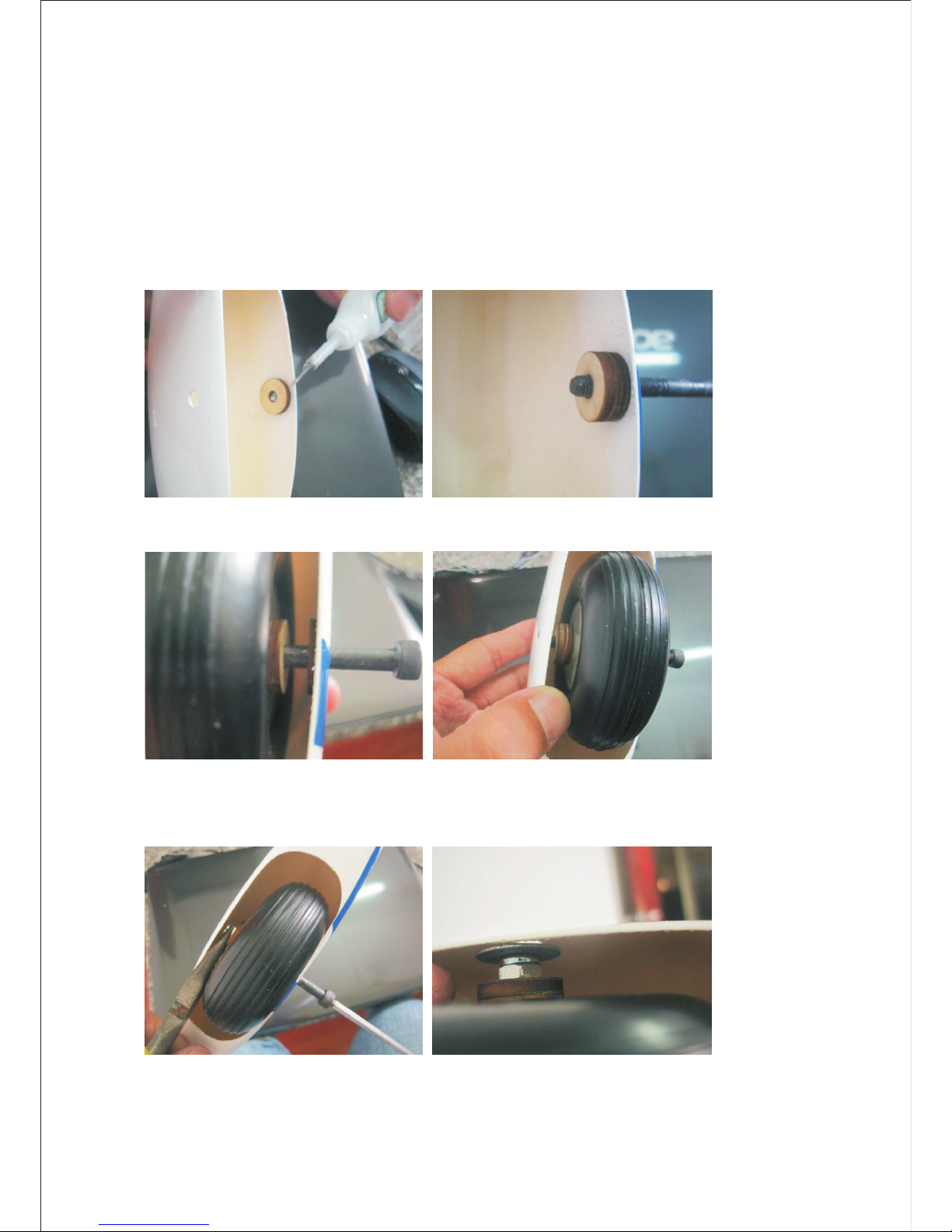
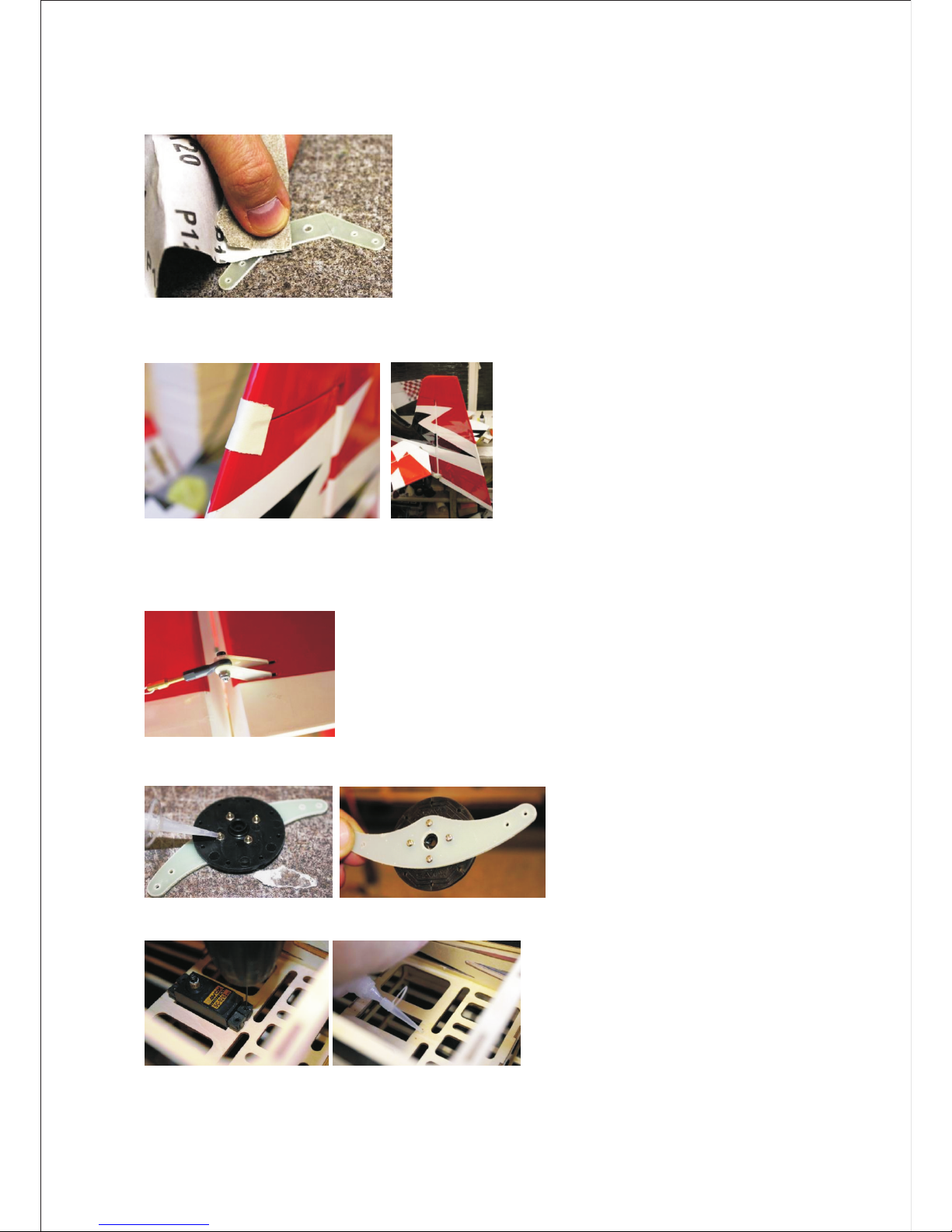
● Sand the area on the horn that fits inside the rudder so the glue bonds better
● Glue the rudder hinges into both the rudder and fin using epoxy glue. Remember to
use Vaseline , use tape to keep it in alignment.on the hinge joint. While drying
● Glue the rudder horns through the rudder with epoxy ;wipe off excess glue while it is
wet. Use the and bolt while gluing to maintain alignment. While still movable ,ball joint
measure that the same ,amount pushes out each side. Care needs to be taken here
otherwise your rudder geometry will be incorrect.
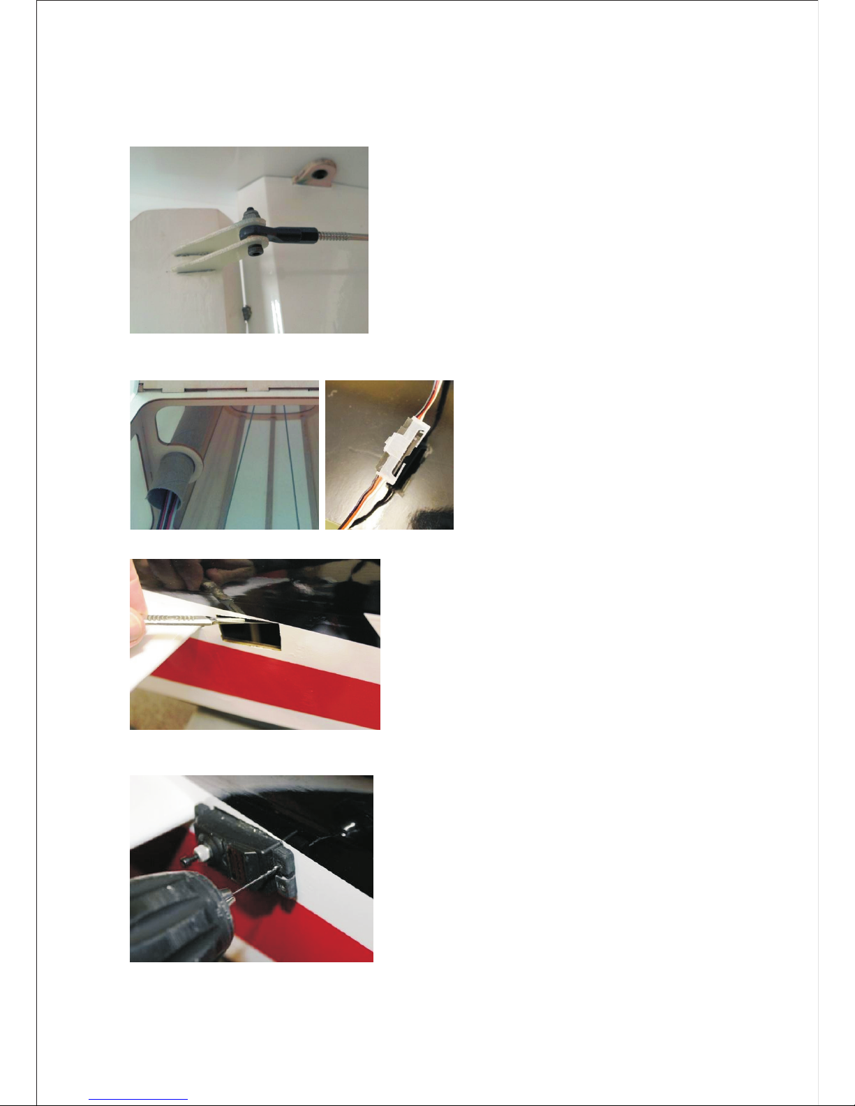
● Assemble the rudder servo control arm as below, drill holes for screws and use C.A
glue to stop the nuts from coming loose.
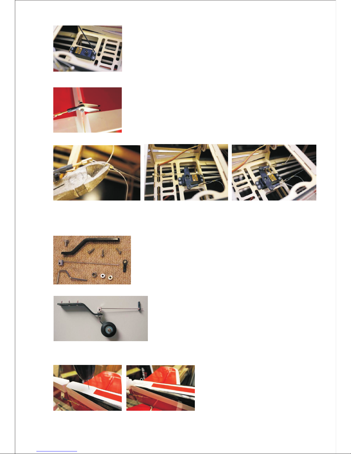
● Fit the rudder servo and drill holes using a fine drill for the servo screws; drop thin C.A glue into the
holes to strengthen the wood.
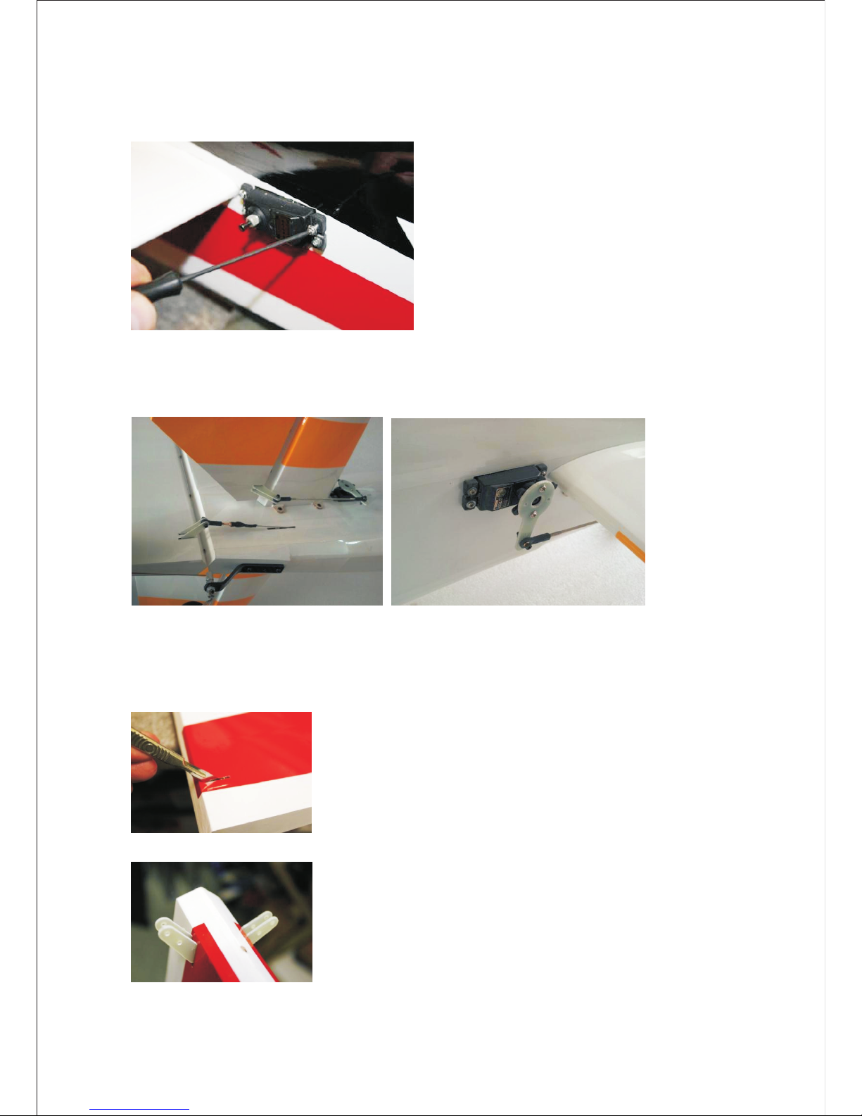
● Using servo screws, fix the servo in place; note that the spline is towards the front of the plane
● The closed loop wires are assembled in the plane; attach the rear ball joints to the rudder. Do this
to both sides.
● Fit the arm onto the rudder servo and crimp the wires to a taut tension
Tail Gear
● Locate all parts as in picture. When assembling, remember to do a thread locker on all parts
● Assemble the Gear as per photo
● At the rear of the fuselage you will find a ply wood area, lay the CF gear on this and mark the 3
holes, taking care to make sure it is straight.
● Drill each hole with a fine drill and drop thin C.A glue into the holes to strengthen the wood.
● Screw the CF gear on with the three supplied self-taping screws.
● Drill a hole in the base of the rudder for the rudder steering guide.
● Before gluing with C.A. glue, place it over the thin rod.
Aileron Servos
● The ailerons on the wings are pre-glued. Check each one by gently pulling to make sure that they
are secure
● Remove the covering where the aileron horns are glued in place. Use either a soldering iron or a
sharp knife
● Using sand paper rough the area that will be glued into the aileron.
● Glue both horns in with epoxy glue; use a bolt through the horns when gluing to make sure the
alignment is correct.
● Fit the aileron servo and drill fine holes where the servo screws will fit. Then apply thin to
strengthen the holes.
● If required, use a servo extension with the servo remember to use a servo plug clip.
●
Fit the servo and centre the servo arm.
● Using the pushrod supplied Ball links onto each end. The correct length will leave the aileron lined
up to the inner part still attached to the wing.
● Using supplied bolts attach the pushrod at both ends. Check to see you have sufficient movement
of the aileron. If not, adjust.
● Carry out the same procedure on the other wing.
Gas Engine
● From the template that came with the engine, use the cross axis on the engine box to mark the
mounting holes.
● Check the diameter of the required bolts and drill accordingly.
● Mount the engine with the stand offs to the bulkhead. Remember to use large washers on the
inside to spread the load and use plenty of thread lockers.
● Exhaust options: Depending on the engine, many exhaust options are available. Standard muffler,
Pitts Exhaust of canister with header.
● If using a canister, a bracket is already inside the model. Using silicon tubing will hold the end of
the canister.
● The front outlet of the canister will pop out of the bottom of the cowl
● Cut out the area for the engine cylinder head and the exhaust outlet on a piece of thin card and
tape this to the fuselage at one end.
● Remove the engine and fit the cowl, then fold the card back over.
● Mark the area and cut out using a dermal. Ensure that enough air can get out of the cowl. The
ratio is usually three times out to one in.
● Fit the ignition on the side of the motor box. Use Velcro and a strap to ensure it does not come off
with vibration.
● The cowl is fixed in 4 places, 2 at the top and 2 at the bottom. Place masking tape over the bottom
2 and pierce where the blind nut hole is.
● Refit the cowl and drill where the marked hole was.
● The fuel tank is pre-installed. Attach petrol proof pipe as per labelling on tank
● Use the supplied pushrod with a ball joint to connect to the throttle arm on the engine. Then find a
convenient place to locate the throttle servo using the supplied mount.
● Install the engine box cover plate once all connections have been made for the engine.
Electric
● Assemble the supplied electric motor box and bolt to the engine bulkhead.
● Depending on the length of your motor you may need to use the supplied round plywood spacers
to achieve the correct length for the motor .
● Mount the ESC in airflow on the side of the electric motor mount using a Velcro strap.
● With the removal of the fuel tank it leaves a large area where the batteries can be mounted.
Switch
●
On each side of the fuselage near the canopy bolts are areas for switches to be mounted.
RX
● A convenient place to mount the RX is just in front of the rudder servo. Ensure that it is mounted
on Velcro and strapped down.
Canopy
● The canopy is held in place with the 2 thumb screws. Ensure these are tight before flying
Set-up
We highly recommend the use of both dual rates and exponential. This will allow the model to fly both
precision and 3D at the flip of a switch.
Low Rates Exponential High Rate Exponential
Elevator 15-20 deg 15-20 % 35-45 deg 45-60 %
Ailerons 15-20 deg 15-20 % 35-45 deg 45-60 %
Rudder 25-30 deg 15-20 % 35-45 deg 45-60 %
For test flights always use low rates; remember that + and – exponential is different per manufacturer.
Check your TX manual.
Always check the range on your model before the maiden flight. Carry out a short flight then go over
everything to make sure nothing has come loose.
CG Location
We suggest for initial test flights that you set the CG 126.5mm from the leading edge of the wing.
Adjust after first flights to personal preference.
Enjoy Flying!!
126.5mm

Other Goldwing Toy manuals

Goldwing EXTRA330SC User manual

Goldwing

Goldwing EXTRA330SC User manual

Goldwing YAK 55M 70 E User manual

Goldwing

Goldwing YAK 55M 70 E User manual

Goldwing 50CC V3 SERIES SBACH300 User manual

Goldwing

Goldwing 50CC V3 SERIES SBACH300 User manual

Goldwing CORVUS RACER EDGE540 User manual

Goldwing

Goldwing CORVUS RACER EDGE540 User manual

Goldwing PITTS 30CC V3 User manual

Goldwing

Goldwing PITTS 30CC V3 User manual

Goldwing SBACH User manual

Goldwing

Goldwing SBACH User manual

Goldwing 76in EDGE540 30-35CC User manual

Goldwing

Goldwing 76in EDGE540 30-35CC User manual

Goldwing 91in SLICK540 60CC User manual

Goldwing

Goldwing 91in SLICK540 60CC User manual

Popular Toy manuals by other brands

Rail King Work Train operating instructions

Rail King

Rail King Work Train operating instructions

Kyosho RC SURFER instruction manual

Kyosho

Kyosho RC SURFER instruction manual

Sutton's Locomotive Workshop British Railways Sulzer Type 2 operating manual

Sutton's Locomotive Workshop

Sutton's Locomotive Workshop British Railways Sulzer Type 2 operating manual

Faller Grandfather clock manual

Faller

Faller Grandfather clock manual

advanced scale models A-26 invader Assembly instructions

advanced scale models

advanced scale models A-26 invader Assembly instructions

krakpol 211086 Assembly instructions

krakpol

krakpol 211086 Assembly instructions

Smoby 7600220375 manual

Smoby

Smoby 7600220375 manual

LGB 2901 instruction manual

LGB

LGB 2901 instruction manual

Mega Bloks 7860 quick start guide

Mega Bloks

Mega Bloks 7860 quick start guide

Mattel Barbie FRH73 instructions

Mattel

Mattel Barbie FRH73 instructions

Eduard P-40C manual

Eduard

Eduard P-40C manual

Horizon Fitness Super Cub dsm instruction manual

Horizon Fitness

Horizon Fitness Super Cub dsm instruction manual

Eduard 48 856 quick start guide

Eduard

Eduard 48 856 quick start guide

Fisher-Price Rain Forest Dancin’ Tunes owner's manual

Fisher-Price

Fisher-Price Rain Forest Dancin’ Tunes owner's manual

Seagull Models Decathlon 60-85cc-3D Assembly manual

Seagull Models

Seagull Models Decathlon 60-85cc-3D Assembly manual

Fisher-Price Pixter Cyberchase owner's manual

Fisher-Price

Fisher-Price Pixter Cyberchase owner's manual

Fisher-Price 77628 instructions

Fisher-Price

Fisher-Price 77628 instructions

Giant Leap Rocketry Liberty 2 instruction manual

Giant Leap Rocketry

Giant Leap Rocketry Liberty 2 instruction manual

manuals.online logo
manuals.online logoBrands
  • About & Mission
  • Contact us
  • Privacy Policy
  • Terms and Conditions

Copyright 2025 Manuals.Online. All Rights Reserved.