33
INTRODUCTION
STARTING RECOMMENDATIONS
INDEX
First of all we would like to thank and congratulate you for the purchase of this product manufactured by
The commitment to reach the satisfaction of our customers is stated through the ISO-9001 certification
andforthemanufacturingofproductslikethisone.
Its advanced technology and exacting quality control will do that customers and users enjoy with the
legion of features this system offers To obtain the maximum profit of these features and a properly wired
installation,wekindlyrecommendyoutoexpendafewminutesofyourtimetoreadthismanual.
Golmar.
.
O
O
O
O
O
O
O
Theinstallationandhandlingofthisequipmentmustbeperformedbyauthorisedpersonnel
Installormodifytheequipmentwithoutthe powerconnected
Donotuseexcessiveforcewhentighteningtheconverterconnectionblockscrews
Before connecting the system, check the connections between door panel, converter, multiplexer,
monitors,telephonesandthepowersupplyconnection.Doalwaysfollowtheenclosedinformation
When starting the equipment for the first time, or after a modification, the system will remain inactive
foraround45secondsduetotheinitialbusychanneltime
UseGolmar cableinthe system
.
O..
Theentireinstallationmustbeatleast40cm.awayfromanyotherinstallation.
.
.
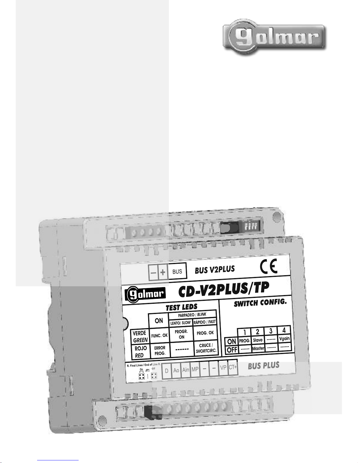
RAP-2150 V2Plus .
Doalwaysfollowtheenclosedinformation.
Introduction........................................................................................................................33
Index .................................................................................................................................33
Startingrecommendations....................................................................................................33
Safetyprecautions...............................................................................................................34
Systemcharacteristics ..........................................................................................................34
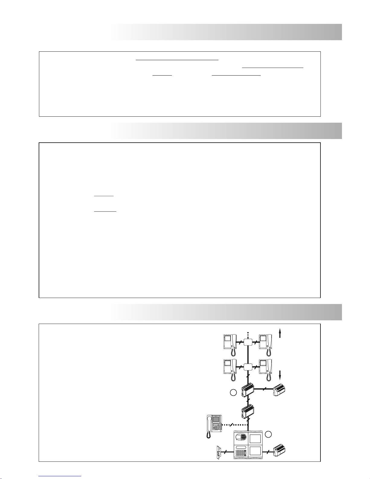
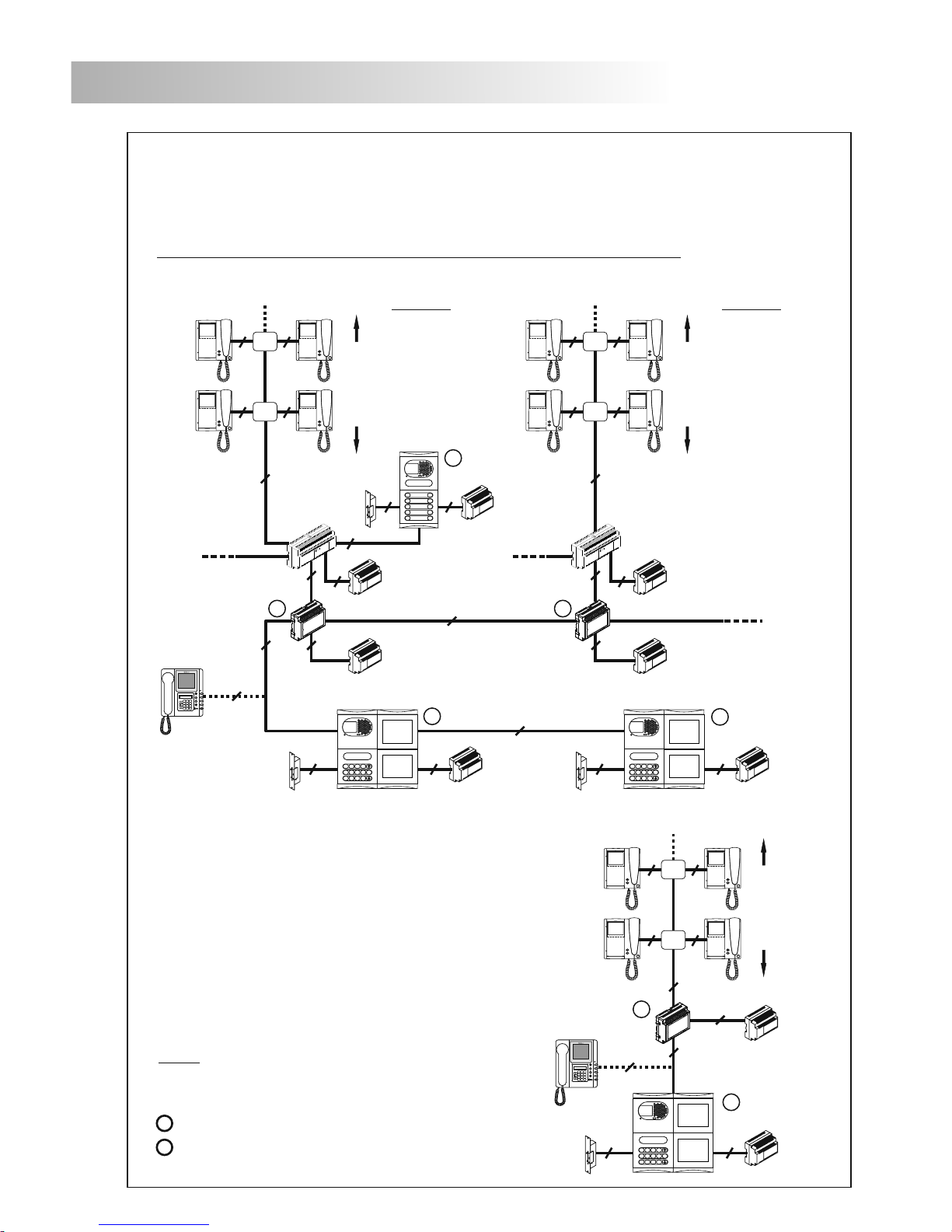
Operationmodes ..........................................................................................................34-35
Description.........................................................................................................................36
Installation .........................................................................................................................36
.............................................................................................................38
Replacement.....................................................................................................................39
Minimumrequirements.............................................................................................39-40
Installationofreplacement.................................................................................................
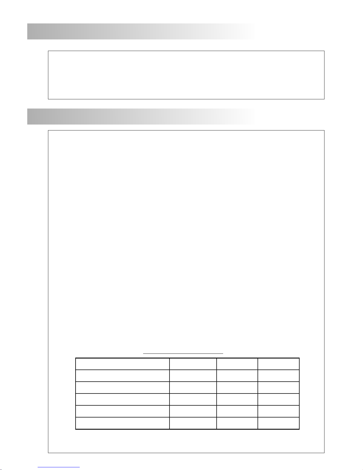
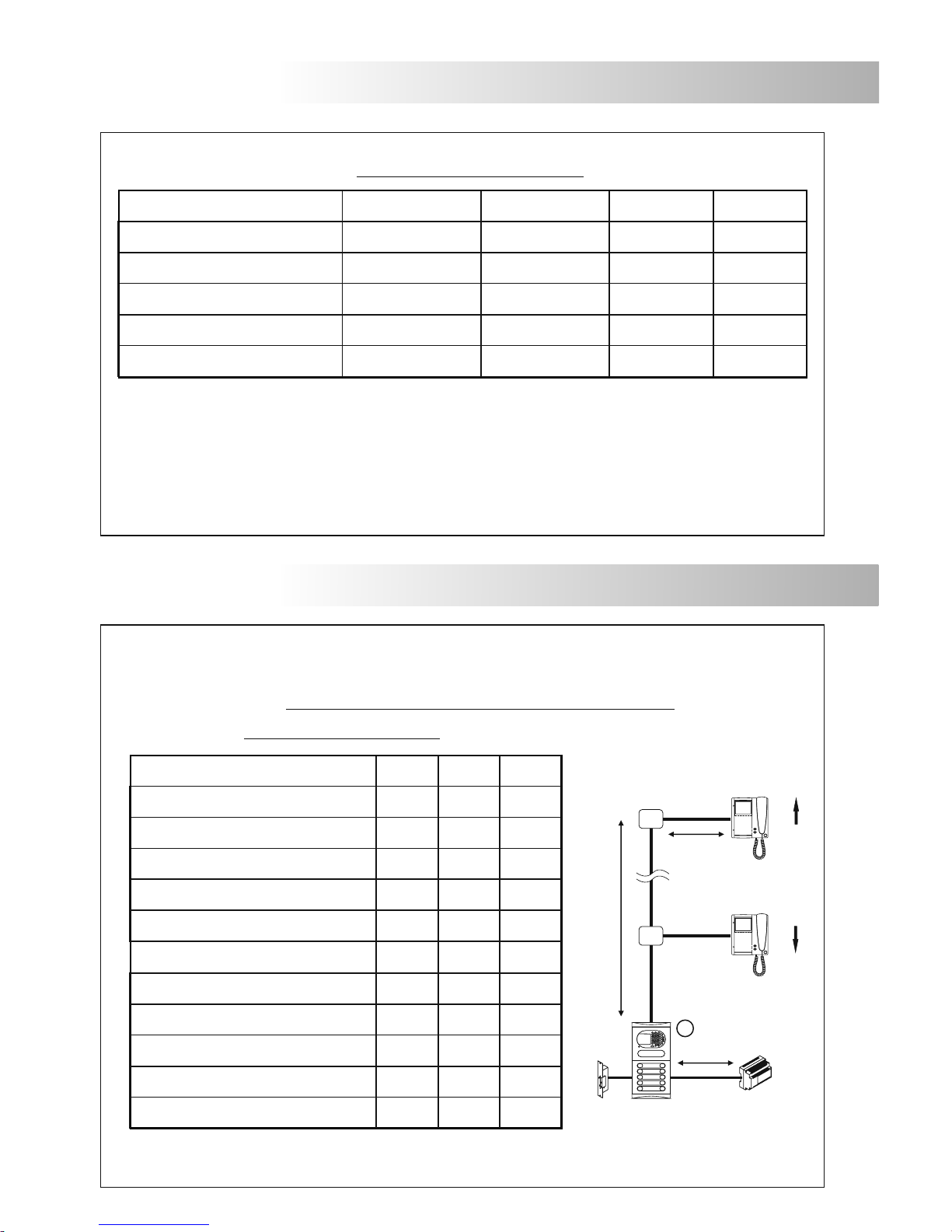
Cable,sectionsanddistanceschart(oneaccessandoneriser).......................................40
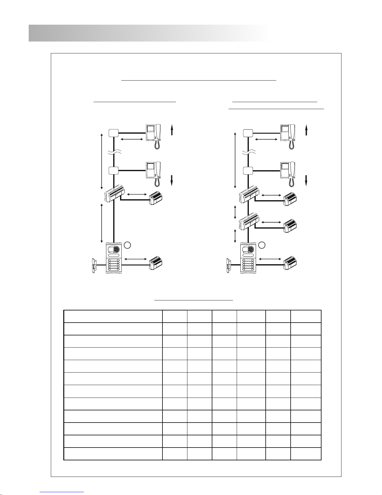
Cable,sectionsanddistanceschart(severalaccessesandrisers)....................................41
Installationdiagrams ...............................................................................................................
Codedpanel....................................................................................................................42
Generaldoorpanel(withoutcoaxialcable).....................................................................43-44
Generaldoorpanel(withcoaxialcable)..........................................................................45-46
Troubleshootinghints...........................................................................................................47
Notes ...........................................................................................................................48-50
Compliance .......................................................................................................................51
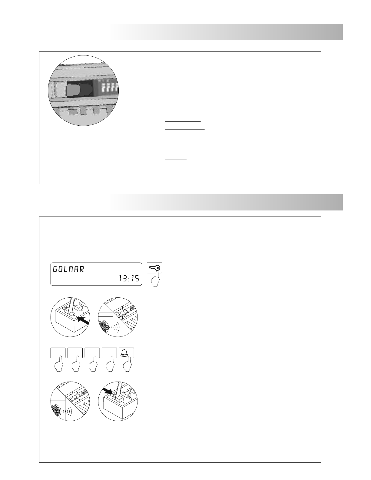
Configurationdipswitch.......................................................................................................37
Configurationjumper(Endoflineresistor) ..............................................................................37
rogrammingtheconverter
AutodiagnosticLeds
P (Backbonecode)..........................................................................38