Gonnheimer Elektronic DC 155 User manual

User's manual
Dosing- Controller
DC 155
Manual DC155 Rev.C03
1

Page 2 1 safety guidelines DC155
Gönnheimer Elektronic GmbH phone.: +49 (6321) 49919-0, fax: -41 Email: info@goennheimer.de
Table of Contents
1
OPERATION INSTRUCTION FOR EXPLOSION PROTECTED CONTROL PANELS ................................... 3
1.1
Application and Standards............................................................................................................................................ 3
1.2
General Instructions ..................................................................................................................................................... 3
1.3
Before using the device ................................................................................................................................................ 3
1.4
Intrinsically Safe Circuits............................................................................................................................................. 3
2
INTRODUCTION: DOSING CONTROLLER DC155 .............................................................................................. 4
2.1
Short description .......................................................................................................................................................... 4
2.2
Basics ........................................................................................................................................................................... 4
2.2.1
Units for preset, sum counter and flow .......................................................................................................................................4
2.2.2
Impulse value, analog input scaling ............................................................................................................................................4
2.3
Dosing applications ...................................................................................................................................................... 5
2.3.1
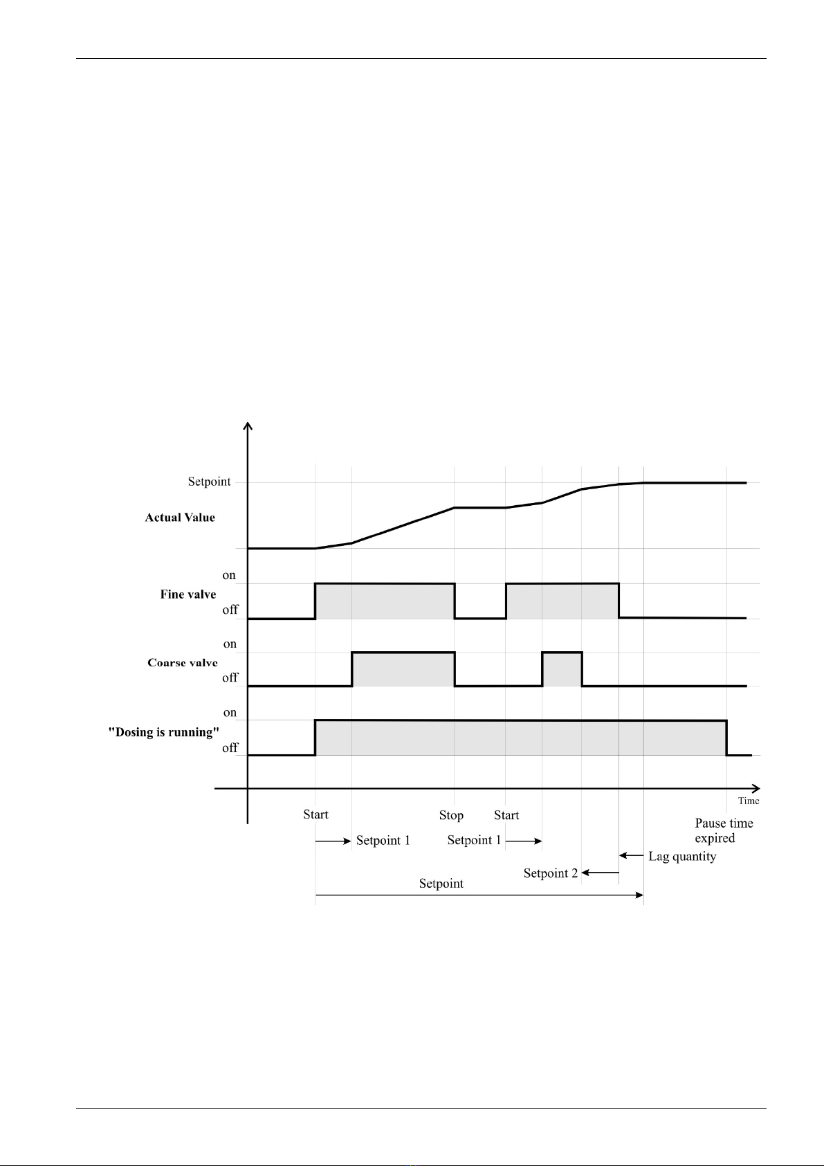
Dosing control using digital solenoid valves...............................................................................................................................5
2.3.2
Dosing control with a proportional (analog) valve......................................................................................................................7
2.3.3
Flow controlled Dosing (Option PID).........................................................................................................................................8
2.3.4
Batch control with absolute level signal (requires 4...20mA analog input option ).....................................................................9
2.3.5
Forward - backward Impulse counter (requires 2 Impulse inputs option)...................................................................................9
2.4
Creep suppression......................................................................................................................................................... 9
2.5
Temperature compensation (requires Pt100- option) ................................................................................................. 10
2.6
Process monitoring..................................................................................................................................................... 11
2.6.1
Broken wire monitoring............................................................................................................................................................11
2.6.2
Flow monitoring........................................................................................................................................................................11
2.7
Safety.......................................................................................................................................................................... 12
2.7.1
Code words ...............................................................................................................................................................................12
2.7.2
Key locking...............................................................................................................................................................................13
2.8
Remote control / bus coupling.................................................................................................................................... 13
2.8.1
Remote control via digital inputs ..............................................................................................................................................13
2.8.2
TTY- interface and protocol print (Option)...............................................................................................................................13
2.8.3
Modbus (Option).......................................................................................................................................................................14
3
OPERATION MANUAL............................................................................................................................................. 15
3.1
LC-Display ................................................................................................................................................................. 15
3.2
Keyboard .................................................................................................................................................................... 16
3.3
Parameter input and Configuration ............................................................................................................................ 17
3.4
Dosing control flow chart........................................................................................................................................... 17
4
STARTING, PARAMETER DEFAULT SETTINGS............................................................................................... 19
5
RESET........................................................................................................................................................................... 20
6
POWER SUPPLY OF THE DC155............................................................................................................................ 21
6.1.1
Application inside hazardous area.............................................................................................................................................21
6.1.2
DC155 for safe area application................................................................................................................................................22
7
INSTALLATION AND CONNECTION ................................................................................................................... 22
7.1
Mounting .................................................................................................................................................................... 22
7.1.1
Panel Mounting.........................................................................................................................................................................23
7.2
Electrical Wiring ........................................................................................................................................................ 23
7.2.1
Terminal description DC155.....................................................................................................................................................24
7.2.2
Power supply.............................................................................................................................................................................25
7.2.3
Sensor terminals........................................................................................................................................................................25
7.2.4
Actor terminals .........................................................................................................................................................................26
7.2.5
TTY interface............................................................................................................................................................................27
7.2.6
RS485 interface.........................................................................................................................................................................27
8
ANNEX.......................................................................................................................................................................... 28
8.1
Block diagram DC155................................................................................................................................................ 28
8.2
Technical Details........................................................................................................................................................ 29
8.3
Transport, storage, disposal and repairs ..................................................................................................................... 29
8.4
Type Code (Configuration example).......................................................................................................................... 30
8.5
Batteries and battery replacement .............................................................................................................................. 30
8.6
Ex-technical terminal limit values.............................................................................................................................. 30
8.7
Documentation table................................................................................................................................................... 31

DC155 1 safety guidelines Page 3
Gönnheimer Elektronic GmbH phone.: +49 (6321) 49919-0, fax: -41 Email: info@goennheimer.de
!
1Operation instruction for Explosion protected control panels
1.1 Application and Standards
This instruction manual applies to explosion protected control panels of type of protection types below. This
apparatus is only to be used as defined and meets requirements of EN 60 079 particularly EN60 079-14
"electrical apparatus for potentiality explosive atmospheres". It can be used in hazardous locations which are
hazardous due to gases and vapours according to the explosion group and temperature class as stipulated on
the type label. When installing and operating the explosion protected distribution and control panels the
respective nationally valid regulations and requirements are to be observed.
1.2 General Instructions
The control panel has to have a back-up fuse as stipulated. The mains connection must have a sufficient short
circuit current to ensure safe breaking of the fuse. To achieve an impeccable and safety device operation,
please take care for adept transportation, storage and mounting, as well as accurate service and maintenance.
Operation of this device should only be implemented by authorised persons and in strict accordance with
local safety standards. The electrical data on the type label and if applicable, the "special conditions" of the
test certificate PTB 98 ATEX 2071 are to be observed.
For outdoor installation it is recommended to protect the explosion protected distribution and control panel
against direct climatic influence, e.g. with a protective roof. The maximum ambient temperature is 40°C, if
not stipulated otherwise.
1.3 Before using the device
All connections and connection points must be checked for correct cabling. Operation with damaged cables
is not permitted.
1.4 Intrinsically Safe Circuits
Erection instructions in the testing certificates of intrinsically safe apparatus are to be observed. The electrical
safety values stipulated on the type label must not be exceeded in the intrinsically safe circuit. When inter-
connecting intrinsically safe circuits it is to be tested, whether a voltage and/or current addition occurs. The
intrinsic safety of interconnected circuits is to be ensured. (EN 60079-14, section 12)
Safety Measures: to read and to comply
Work on electrical installations and apparatus in operation is generally forbidden in hazardous locations, with
the exception of intrinsically safe circuits. In special cases work can be done on non-intrinsically safe circuits,
on the condition that during the duration of such work no explosive atmosphere exists. Only explosion pro-
tected certified measuring instruments may be used to ensure that the apparatus is voltage-free. Grounding
and short circuiting may only be carried out, if there is no explosion hazard at the grounding or short circuit
connection.
Safety aspects
A batch control system built exclusively with the DC155 represents a
control system in category 1 according EN954-1. If a higher safety is
required, it is necessary to install independent working safety
facilities.

Page 4 4 manual DC155
Gönnheimer Elektronic GmbH phone.: +49 (6321) 49919-0, fax: -41 Email: info@goennheimer.de
2Introduction: Dosing controller DC155
2.1 Short description
The dosing controller DC155 is an all-purpose dosing control device to manage batch controlling of any
arbitrary liquids or solid products inside the hazardous area. Advantages of this device are:
•simply handling, an orderly key pad containing big (22 x 22 mm) keys,
•a large graphic display and a
•flexible wide functionality.
The DC155 can manage simple as well as complex dosing applications inside hazardous areas, without an
extensive wiring to a distributed control system. See advantages below:
Several Input sources
It is possible to connect any common transmitter: NAMUR or 24V digital inputs
are the standard input terminals, 4 up to 20 mA input as an option.
Temperature
compensation
The additional Pt100- input terminal allows a temperature compensation, if the
space expansion factor γof the dosing product is known and not negligible.
Intelligent dosing
features
The intelligent dosing program of the DC155 prevents shocks on the pipe system
using a continuous raise and fall ramp by the 4 up to 20 mA – proportional valve
output, as well as using a pair of fine and coarse valve.
Intelligent batch
monitoring
Furthermore, the DC155 includes a trouble alarm system to report flow disturb-
ances or sensor failures. The flow monitoring can be delayed to prevent wrong
alarm during the start and finish period of the batch.
Simply remote
control
The DC155 has several digital control inputs to realise a simple remote control
with the basic functions like “START, STOP and RESET”.
Powerful analog
output
The analog output can manage a load of 600 Ωdirectly.
PID-controlled
Dosing process
Some applications need a regulation of the flow during the batch process. The
option “regulated analog output” can manage these applications with an internal
PID- controller.
Data safety
The data is stored on an onboard non-volatile memory, if the power supply fails.
The DC155 continues at the restored state, when the mains is back.
2.2 Basics
2.2.1 Units for preset, sum counter and flow
The first step to configure the DC155 is to define the physical unit for preset, sum counter and flow. There-
fore, sufficient unit symbols are implemented into the DC155 (e.g. gram (g), kilogram (kg), tons (t), liter (l)
etc.) To define the flow several time units are available.
2.2.2 Impulse value, analog input scaling
The DC155 gets its information about the present flow via impulse or an analog signal from a flow sensor.
If it is an impulse signal, you have to define the value of one impulse to get the right amount of flow. If the
sensor signal is an analog signal, you have to define the maximum flow (e.g. 1000 kg/min) for 20 mA. The
Impulse value and analog input scaling are located in the structure menu in the input category.

DC155 4 manual Page 5
Gönnheimer Elektronic GmbH phone.: +49 (6321) 49919-0, fax: -41 Email: info@goennheimer.de
2.3 Dosing applications
Generally, a batch control system content a flow measuring, one or two valves and the batch controller.
The flow sensor measures the quantity of the product per time, which flows into the target bowl and sends
this information to the batch controller. The controller receives the flow information, integrates the flow
signal to a sum, compares the sum continuously with the preset value and controls the connected actors,
which themselves control the flow into the target bowl.
The DC155 supports many sensor signals: 24V active/passive, NAMUR, 4...20 mA (analog current signal)
and several actors. The following chapters show application examples sorted by the kind of actors.
2.3.1 Dosing control using digital solenoid valves
The most common dosing application is by using coarse and fine valves. After starting the batch process, the
fine valve opens first. When the quantity given by setpoint 1 has been reached, the coarse valve opens and a
big flow starts. Before the setpoint is reached (at setpoint value minus setpoint 2 value) the coarse valve shuts
and the remaining quantity will be added very exactly.
Additionally, it is possible to configure a lag quantity. This is the run-on quantity after both valves have been
closed.
Besides it is possible to define a maximum setpoint value, to allow only equal or smaller setpoints to be set.

Page 6 4 manual DC155
Gönnheimer Elektronic GmbH phone.: +49 (6321) 49919-0, fax: -41 Email: info@goennheimer.de
The DC155 has three free programmable digital outputs. In the example above two of them must be
reserved for valve control.
The polarity of each output can be configured as "normally open" or "normally closed".
The following figure shows any possible function of a digital output.
Figure 1 Digital output functions
Function Description (definition: output in normal open connection)
1. Counter = 0 The digital output is active, if the actual value is equal to zero. Otherwise the digital
output is inactive.
2. Fine valve Control output for a valve with a fine cross section.
Also, the control output for a single valve.
3. Coarse valve Control output for a valve with a wide cross section.
4. Dosing is running The output is active as long as the dosing is running and the pause time is not ex-
pired. Otherwise the digital output is inactive. See also the time diagram above.
5. Any failure The output is active as long as any failure (broken wire, flow to big, etc) is occur-
ring. The output remains closed until the failure has been fixed and has been
acknowledged by pressing the reset key. Otherwise the digital output is inactive.
6. Flow to small The output is active as long as the flow rate is too small and the failure is not
acknowledged. Otherwise the digital output is inactive.
7. Flow too big The output is active as long as the flow rate is too big and the failure is not
acknowledged. Otherwise the digital output is inactive.
8. Impulses The output provides one pulse for any increment of the pre-decimal place of the ac-
tual value.
Table 1: Function list of the digital outputs
The total quantity of all batch processes is added and stored by a sum counter. The sum counter is shown
permanently at the bottom of the display. The sum counter can be reset by the user manually. It provides
information about the dosed product over several batches or over a longer period of time.
Furthermore, it is possible to realise a very simple batch control using only one digital solenoid valve. In
this case you have to configure the single valve as a fine valve. Consider, the parameters like setpoint 1 and
setpoint 2 (but not the lag quantity!) lose their functions.
Select the function of
digital output 1:
0. No function
1. Counter = 0
2. Fine valve
3. Course valve
4. Dosing is running
5. Any failure
6. Flow too small
7. Flow too big
8. Impulses
.
End

DC155 4 manual Page 7
Gönnheimer Elektronic GmbH phone.: +49 (6321) 49919-0, fax: -41 Email: info@goennheimer.de
2.3.2 Dosing control with a proportional (analog) valve
The DC155 can optionally get supplied with a 4...20 mA analog output to control a proportional solenoid
valve. In this case, the analog output has to be configured as "Ramp shape".
It is possible to set the maximum value of the analog output, the starting value and the ending value by using
the following three parameters (percentage values): "Limit for analog output", "Start value of the rising
ramp" and "End value of the falling ramp".
The analog output can get configured as:
0...20 mA : 0% = 0mA, 100% = 20mA
4...20 mA : 0% = 4mA, 100% = 20mA
The dosing quantity is set with the parameter "setpoint". The rising ramp is determined by the parameter
"setpoint 1", the falling ramp by "setpoint 2". The ramp is determined by the filling quantity, not by the time.
This means that the analog output is at its maximum after the quantity "Setpoint 1" has been filled and not
after a given time.
The meaning of all these parameters is demonstrated with the following diagram.

Page 8 4 manual DC155
Gönnheimer Elektronic GmbH phone.: +49 (6321) 49919-0, fax: -41 Email: info@goennheimer.de
Any alternative functions for the analog output are shown below:
Figure 2 Functions of the analog output
Function Description (definition: output in normal open connection)
1. Flow prop. signal Ratio: "actual flow / max. flow"
T
he value of "
max flow
"
is set
in the input menu
.
2. Ramp shape
C
ontrol
of
a proportional
(analog)
solenoid valve
,
s
ee working diagram above
3. Flow feedback control
O
utput of PID
flow control
ler
(
generate a
configurable flow rate
)
4.
Counter prop. signal
R
atio "
a
ctual counter value" to "setpoint"
5. Counter (max)
p
rop
.
sig
nal
Ratio "actual counter value" to "max. setpoint"
The value "
m
ax
. setpoint
" is set in the setpoints
-
menu.
6. Setpoint prop. signal
Ratio "setpoint" to "max. setpoint"
2.3.3 Flow controlled Dosing (Option PID)
Optionally, the DC155 can have an internal PID flow controller, so that the dosing can be carried out with
an adjustable flow rate. The PID parameters Kp, Ki, Kd and the flow setpoint can be configured in the pa-
rameter menu.
In the mode "Flow Feedback Control", it is possible to define a ramp similar to the uncontrolled output when
using the function "Ramp shape". There is one important difference: The ramp defined in the mode "Ramp
shape" represents the analog output value directly (100% = 20mA). The ramp in the mode "Flow Feedback
Control" refers to the PID flow setpoint. The flow setpoint represents 100%. For example, it is possible to
start the PID controller with 20% of the flow setpoint and ramp up to 100% slowly.
Q
setpoint
= Flow Setpoint
Q
actual
= Actual Flow at the time k
The sampling rate of the digital PID controller is 20ms.
Normalized error value:
Control Signal:
The PID parameters Kp, Ki and Kd are percentage values.
The control signal y is a percentage value, too. The value 100% corresponds to 20mA. If the analog output
range was configured to 4...20mA, 0% corresponds to the value 4mA. With an analog output range of
0...20mA, 0% corresponds to the value 0mA.
Settings for analog output:
0. No function
1. Flow prop. signal
2. Ramp shape
3. Flow feedback control
4. Counter prop. signal
5. Counter (max) prop. signal
6. Setpoint prop. signal
. End

DC155 4 manual Page 9
Gönnheimer Elektronic GmbH phone.: +49 (6321) 49919-0, fax: -41 Email: info@goennheimer.de
2.3.4 Batch control with absolute level signal (requires 4...20mA analog input option )
This kind of batch control does not work with a flow signal, but with an absolute level signal. You can either
measure the level in the container that is being filled (level rises during dosing) or the level of the container
from which the material to be dosed is removed (level falls during dosing). The valves are controlled as in
the other operating modes. Flow monitoring or displaying is not possible in this mode.
2.3.5 Forward - backward Impulse counter (requires 2 Impulse inputs option)
Some kinds of flow sensors (e. g. windmill-type anemometer) recognises back flows. These have two sensor
signals. The DC155 can determinate the flow direction using the phase relation of the two signals.
Configuration and handling of the DC155 with this option is equal to any standard application.
2.4 Creep suppression
In some applications, when using 4-20mA analog
inputs, it is necessary to suppress adding up small
flow quantities.
The figure on the right hand shows its function.
Adjust the creep suppression value in the structure
menu.
Figure 3: creep suppression

Page 10 4 manual DC155
Gönnheimer Elektronic GmbH phone.: +49 (6321) 49919-0, fax: -41 Email: info@goennheimer.de
2.5 Temperature compensation (requires Pt100- option)
Any fluid has a specific expansion coefficient γ. The volume of the fluid increases with its temperature.
Using a volume measurement sensor for a mass dosing application, introduces an inaccuracy into the dosing
process, if the temperature is not taken into account.
The DC155 can compensate the thermal expansion of a fluid according to the following formula:
!"!
#$ %" "
&
V(ϑ) volume at actual temperature
V
0
volume at reference temperature
ϑactual fluid temperature
ϑ
0
reference temperature
γexpansion coefficient
The DC155 measures the temperature of the fluid with a Pt100 temperature sensor. The user can set the
values of the expansion coefficient and the reference temperature with the "Temperature compensation"
menu.
The signs of the temperature values are entered by using the arrow keys. The left arrow sets a negative sign,
the right arrow sets a positive sign.
The temperature measurement value can be monitored. This allows to recognise broken wires and short cuts of
the Pt100 wiring. The DC155 uses a default value, if the Pt100 temperature is outside the configured temperature
range, given by the parameters "Minimum Value" and "Maximum Value". The dosing process can either be
stopped or continued in that case. Additionally, it is possible to activate any digital output whose functionality has
been set to "Any failure".
Temperature Compensation
0. Temperature compensation: active
1. Reference temperature: 20°C
2. Coeff. of expansion: 0.100E-3 1/K
3. Temperature monitoring: Yes
4. Minimum value: -10°C
5. Maximum value: 50 °C
6. Default value: 20°C
7. Stop Dosing: Yes
8. Error signal: Yes
. End

DC155 4 manual Page 11
Gönnheimer Elektronic GmbH phone.: +49 (6321) 49919-0, fax: -41 Email: info@goennheimer.de
You can see whether the temperature is within the permitted range in the lower right corner of the display:
The marking "Err:" shows that the temperature is out of range. The marking "Temp:" shows that the
temperature is OK. If the dosing process is running, the display shows always the temperature that is
used for dosing. This can be the measured value or the default value, if the temperature is out of range.
When no dosing process is running, the value that is displayed is always the measured value. In case of
a temperature error, the user can see, if the temperature is just a few degrees out of the range or if there
is a short cut or an open wire.
If the dosing has been stopped because of a temperature error, an error message appears on the display.
The error state can only get exited if the temperature problem is resolved. The error must
get acknowl-
edged by pressing the RESET- key. A further push on the RESET- key resets the DC155 batch counter to
zero. Alternatively, it is possible to continue the batch process by pressing the START- key.
2.6 Process monitoring
A dosing process can get interrupted due to various error causes. In these cases, it is possible to give an alarm
by using one of the digital outputs. Please consider the dosing process flow chart in chapter 3.4.
2.6.1 Broken wire monitoring
Broken wires can get detected by using NAMUR- signals as digital input signals or 4...20 mA signals as
analog input signals.
In case of a broken wire, the DC155 interrupts the dosing process and indicates "Broken wire" on the
display. It is possible to report the "Broken wire" error using any digital output.
The DC155 remains in the error state until the "Broken wire" error is resolved. Afterwards, the user can leave
the error state by pressing the RESET- key. A second push of the RESET- key resets the DC155 batch
counter to zero. Alternatively, it is possible to continue the batch process by pressing the START- key.
2.6.2 Flow monitoring
The DC155 can monitor minimum and maximum flow limits. If the flow exceeds these limits, the DC155
interrupts the dosing process after a programmable time delay and indicates the error on the display. It is
possible to report the error by using any digital output.
Figure 4 shows an example for the flow at the beginning of a dosing process. The delay times are as follows:
t
a
: General delay before the flow monitoring starts
t
b
: Selective delay at F > F max
t
c
: Selective delay at F < F min
Dosing process Pt100-temperature
inside permitted range
Pt100-Temperatur
outside permitted range
not running "Temp: Measured Value °C" "Err: Measured Value °C "
running "Temp: Measured Value °C" "Err: Default value °C "

Page 12 4 manual DC155
Gönnheimer Elektronic GmbH phone.: +49 (6321) 49919-0, fax: -41 Email: info@goennheimer.de
The general delay t
a
starts on the beginning of the dosing process. No Flow monitoring takes place during
this time. Afterwards selective delays (t
b
and t
c
) start at the moment the flow exceeds its limits. If the flow
doesn't return while the selective delay time is running, the DC155 interrupts the dosing and indicates the
error on the display. It is possible to report the error by using any digital output.
The user can leave the error state by pressing the RESET- key. A second push of the RESET- key resets
the DC155 batch counter to zero. Alternatively, it is possible to continue the batch process by pressing
the START- key.
2.7 Safety
Thoughtlessness and carelessness of unauthorised people are often the cause of failures of automatic dosing
systems. We took measures on the DC155 to prevent unintentional or incompetent interruptions to the dosing
process.
2.7.1 Code words
The permission to enter or manipulate parameter settings is divided into 3 safety levels. Each safety level has
its own programmable access code.
1. The lowest level is the permission to change the quantity setpoint. Authorised persons, who know the
"setpoint" access code are only able to change the quantity setpoint and nothing else.
The factory setting of this access code "0001". A value of "0000" disables the need of entering an
access code to change the quantity setpoint.
2. The medium safety level is the permission to change settings in the parameter menu. In this menu, it
is possible to change parameters like "setpoint 1", "setpoint 2", "lag quantity", "pause time", "flow lim-
its", PID-controller parameters, time and date as well as resetting the sum counter. The factory setting
of this access code "0002". Entering the parameter menu access code cannot get disabled by setting
the access code to "0000". The medium safety level is dedicated to maintenance personal.
3. The highest safety level is the permission to change the settings of the structure menu. In this menu, it
is possible to change the entire structure (configuration) of the DC155 (e.g. dosing method, units, input
signal definition, output signal definition, temperature compensation, flow monitoring, display
t
Max
Min
Flow
F
F
t t t t
a
b
b
c

DC155 4 manual Page 13
Gönnheimer Elektronic GmbH phone.: +49 (6321) 49919-0, fax: -41 Email: info@goennheimer.de
configuration, key blocking) as well as changing code words. The factory setting of this access code
"0003". Entering the structure menu access code cannot get disabled by setting the access code to
"0000". The highest safety level is dedicated to plant engineers.
2.7.2 Key locking
In some applications the DC155 is controlled using a decentralized control system (DCS) with no need for
manual control. In these cases, it is possible to block some or all keys of the DC155 to prevent an unauthorised
intervention.
The DC155 has three key locking levels:
1. Any key is enabled
2. Any key is locked, except the START, STOP and RESET keys
3. Any key is locked
The key locking is only active, if the key lock signal input (terminal 15) is high.
2.8 Remote control / bus coupling
The DC155 has several interfaces for remote control.
2.8.1 Remote control via digital inputs
The DC155 has five predefined digital inputs (START, STOP, RESET, INHIBIT and KEY LOCK) to
realise a simple remote control with active or passive switches.
The polarity of these inputs, except the STOP input, is "normally open". There are two STOP inputs: one is
"normally close", the other is "normally open".
2.8.2 TTY- interface and protocol print (Option)
The DC155 can also get controlled by using the serial TTY-interface and ESC -sequences, see the instruction
codes in the following table:
Instruction code Function
ESC 0 Reads the actual counter value
ESC S START- instruction
ESC P STOP- instruction
ESC Z RESET- instruction
ESC K1 Enable keys (equals setting the keylock-input low)
ESC K0 Lock keys (equals setting the keylock-input high)
ESC B SETPOINT Sets the quantity setpoint
ACK (hex. 06) Answer to a known instruction
NAK (hex. 15) Answer to an unknown instruction

Page 14 4 manual DC155
Gönnheimer Elektronic GmbH phone.: +49 (6321) 49919-0, fax: -41 Email: info@goennheimer.de
Receiving a "ESC Z" instruction , the DC155 answers with a complete batch protocol print (date, time,
quantity setpoint, filled quantity), if the feature "print protocol" has been enabled (Menu/structure/TTY in-
terface).
a) Print out format
b) Info text
It is possible to print out an info text. The text length is 20 characters at maximum. The text can be entered
in menu “TTY- interface”, choosing “info text”. A list with all available characters is displayed. Select a
character with an arrow buttons and put it into text with the enter button.
Delete wrong characters with "<" and confirm the info text with .
c) Central printer for several batch control stations
Use a “Auto data switcher” in the safe area to connect several batch controllers to one printer. The print outs
can be distinguished by individual info text headers.
2.8.3 Modbus (Option)
a) Registers
The modbus interface uses only "Holding Registers" to submit measurement values and commands. The registers
are defined as below:
Register
(Hex)
Access Data format Function
40001
R/W
R/W
R/W
R
R
R
R
R
R
R
R
Bit field Ctrl-Flags:
Bit 0: Start Dosing process
Bit 1: Stop Dosing process
Bit 2: Reset Counter
Info-Flags:
Bit 8: Dosing process is started
Bit 9: Dosing process is stopped
Bit 10: Counter is equal to zero
Bit 11: Broken wire Sensor 1
Bit 12: Broken wire Sensor 2
Bit 13: minimum flow rate alarm
Bit 14: maximum flow rate alarm
Bit 15
C
ounter overflow
40002
R/W Floating point Quantity setpoint
40003
40004
R Floating point Actual quantity value
40005
40006
R Floating point Flow rate
40007
[info text]
[date] [time] [quantity setpoint] [filled quantity]
Input the infotext:
ABCDEFGHIJKLMNOPQRSTUVWXYZ0123456789 . <
Batch position 1

DC155 4 manual Page 15
Gönnheimer Elektronic GmbH phone.: +49 (6321) 49919-0, fax: -41 Email: info@goennheimer.de
The read only bits in the Register 40001 are ignored when writing to this register. The registers 40002 and 40003
must be written simultaneously by using the modbus function 16 "Preset Multiple Registers".
b) The DC155 supports the following modbus functions:
Function number
Function
3
Read Holding Registers
6
Preset Si
ngle Register
16
Preset Multiple Registers
c) Hardware
The DC155 supports Modbus RTU, using 9600 Baud. The parity can be set to even, odd or inactive.
3Operation manual
The DC155 is controlled by the front keys and the display. A restricted control is possible by using the digital inputs or by
using a serial interface.
3.1 LC-Display
The graphical display of the DC155 consists of two big variable text fields and further text and graphic
elements. Every important process data is visible.

Page 16 4 manual DC155
Gönnheimer Elektronic GmbH phone.: +49 (6321) 49919-0, fax: -41 Email: info@goennheimer.de
3.2 Keyboard
The DC155 has 14 keys and a STOP- switch, for complete configuration, parameter changing and manual
operation. The functions of these keys are listed below.
Key Name State Function
STOP-
Switch
1. During dosing process
2. Else
Valves are closed immediately,
dosing process is interrupted
None
START- key 1. Dosing process
stopped / ready
2. While menu input
Dosing process continues / starts,
valves are opened
Cursor shift left
RESET- key 1. Dosing process
finished / stopped
2. During power on
3. While menu input
Resets actual value
Activates parameter reset,
parameters are reset to factory settings
Cursor shift right
SET- key 1. In operation
2. Else
Sets the quantity setpoint
None
INFO- key 1. In operation
2. While menu input
Toggles between status view of the dosing
process and input/output view
Digit "0"
ENTER- key 1. In operation
2. While menu input
Starts structure and parameter menus
(Code word is necessary)
Confirms input / returns to upper menu
Digit keys 1. In operation
2. While running menu
3. While digit input
No function
Select menu item X
Select the digit X

DC155 4 manual Page 17
Gönnheimer Elektronic GmbH phone.: +49 (6321) 49919-0, fax: -41 Email: info@goennheimer.de
3.3 Parameter input and Configuration
It is not necessary to read the following section, if you want to go ahead quickly.
Press the ENTER- key to start the access code input. The factory setting of the access code for entering the
main menu with access to the structure menu is "0003". Confirm the access code with the ENTER- key.
3.4 Dosing control flow chart
The following flow chart depicts the dosing control process. Consider that pressing the "ENTER"- key and
entering the right code word will terminate this procedure in any state. After returning to the dosing operation
the procedure starts on the start position.
If you start the parameter or the structure menu while a dosing pro-
cess is running, the dosing is stopped immediately:
the valves close, the actual value is reset to
"0".
Main menu
0. Language
1. Structure
2. Parameter
3. Codes
4. Reset sum counter
End

Page 18 4 manual DC155
Gönnheimer Elektronic GmbH phone.: +49 (6321) 49919-0, fax: -41 Email: info@goennheimer.de

DC155 5 Annex Page 19
Gönnheimer Elektronic GmbH phone.: +49 (6321) 49919-0, fax: -41 Email: info@goennheimer.de
4Starting, parameter default settings
The following table shows the parameter settings defaults. These basic defaults exist on each DC155. The
parameter count can increase by any additional option.
1. Level 2. Level Parameter Value Comment
Language German, English, French,
Dutch
English
Structure Units Type (mass, volume)
Setpoint:
Sum counter:
Flow:
mass
000000 kg
000000000 kg
0000000 kg/s
Dosing method Flow
Level
Flow
D
evices with analog output
Input (Flow) Namur, 24V,
0/20mA, 4/20
mA
24V input
Type of the input signal
Impulse value
Max. Flow
1.000000kg
0 kg/s
Digital flow sensor:
Namur or 24V input
Flow at 20mA
Creep
ing suppression
0 kg/s
0 kg/s
Analog flow sensor:
0/20mA or
4/20mA
Input (Level) 0/20mA or 4/20mA
rising / falling
Level at 20mA
4/20mA
sinking
0 kg
Devices with analog output:
Level rises or falls while dosing
Output Dig. output 1
Dig. output 2
Dig. output 3
No function
No function
No function
Function of the output
Dig. output 1
Dig. output 2
Dig. output 3
Normally closed
Normally closed
Normally closed
Polarity of the output
"normally closed" or
"normally open"
Type of Analog Output
Function of Analog Output
4/20 mA
No function
Devices with analog output
Flow monitoring
Active / Inactive
Inactive
Not, if
Dosing method = Level
Temperature
Compensation
Active / Inactive
Reference Temperature
Coeff. of expansion
Temperature monitoring
Minimum value
Maximum value
Default value
Stop Dosing
Error signal
Inactive
20°C
0.000E-3 1/K
No
-20°C
99°C
20°C
No
No
Devices with Pt100 input
Parameters for temperature monitoring:
Display Upper display
L
ower display
Setpoint
Actual value
Serial Interface Baud rate
Bits
Parity
Print protocol
9600
8
No
No
Devices with TTY/RS485
- without modbus protocol
Parity
Swap High/Low byte
Device address
No
No
1
Devices with TTY/RS485
- with modbus protocol
Key locking
Enable / Disable
Key
s
enabled
All
key
s
are
active

Page 20 5 Annex DC155
Gönnheimer Elektronic GmbH phone.: +49 (6321) 49919-0, fax: -41 Email: info@goennheimer.de
1. Level
2. Level
Parameter
Value
Comment
Parameter Setpoints Max. Setpoint
Setpoint
Setpoint 1
Setpoint 2
Lag quantity
999999 kg
0 kg
0 kg
0 kg
0 kg
Flow monitoring Minimum Flow
Maximum Flow
General delay
Selective delay F<Fmin
Selective delay F>Fmax
0 kg/s
0 kg/s
1s
1s
1s
only visible, if Flow Control has been
activated in the structure menu
PID Flow Control Flow setpoint
Kp
Ki
Kd
0 kg/s
0
0
0
only visible, if the function of the ana-
log output has been set to "Flow feed-
back control"
Analog Output Max. value of ramp
Start value of rising ramp
End value of falling ramp
100%
100%
100%
Analog Output = "Ramp shape":
100 % = 20mA
Analog Output = "PID Flow control":
100% =
PID
Flow setpoint
Pause time
Pause time
0 s
date
time
-
-
Codes Setpoint
Parameter
Structure
0001
0002
0003
5Reset
Reset
Reset the DC155 to the factory defaults as follows: press the
"RESET" key while you're switching on the power supply to
the DC155.
After a reset the display shows:
The DC155 has been reset.
All parameters are cleared.
It is necessary to reconfigurate
the DC155 !!!
Press START key
Other manuals for DC 155
1
Table of contents
Other Gonnheimer Elektronic Controllers manuals
Popular Controllers manuals by other brands

HP
HP MSM7XX reference guide

Weinzierl
Weinzierl KNX IO 532 Operation and installation manual

Faulhaber
Faulhaber MC 5004 Technical manual

KMC Controls
KMC Controls MCP-1020 Series installation guide

Broadcast Pix
Broadcast Pix VOX Operator's manual

MarelliGenerators
MarelliGenerators M40FA640A/A MARK I user manual

Mitsubishi Electric
Mitsubishi Electric FX3G SERIES Programming manual

TELEVAC
TELEVAC Compact 2A instruction manual

Edge Lighting
Edge Lighting CDP installation instructions

Missouri Wind and Solar
Missouri Wind and Solar Suntaqe SUN 12V100 quick start guide

Thermaltake
Thermaltake CL-O016-PL00BL-A installation guide

Eagle
Eagle A3 Pro quick start guide