GORE Aerospace User manual

1
Termination
Instructions
GORE®Aerospace
Ethernet Cables
TE Connectivity®CeeLok FAS-X®Connector System
The following procedures are based on Gore’s best practices
for terminating GORE®Aerospace Ethernet Cables with the TE
Connectivity®CeeLok FAS-X®Connector System for both pin and
socket versions. These procedures should be used as a guide in
conjunction with current connector manufacturing instructions.
Preparing the Cable and Parts
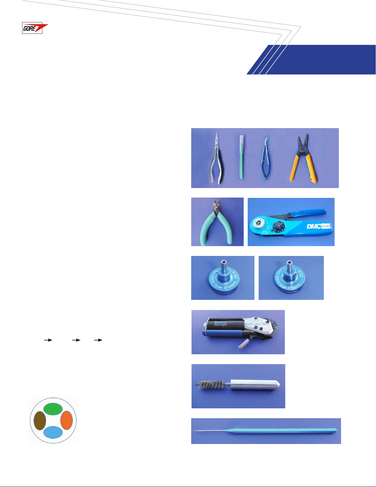
1. Gather the tools and materials required for assembly and
termination (Figures 1–8).
2. Verify that you have the correct parts for your assembly by
checking the part numbers for the connectors and the GORE®
Aerospace Ethernet Cables listed on drawing DDA0238.
3. Cut two 1.5-inch pieces of 5/8-inch, thin-walled adhesive-lined
tubing (TAT).
4. Cut the cable to the desired assembly length minus 4.3
centimeters (cm) to allow for length of the connectors (i.e.,
2.0 cm for the plug connector and 2.3 cm for the receptacle
connector).
5. Print any labels required by the end-user, and slide the center
label onto the cable.
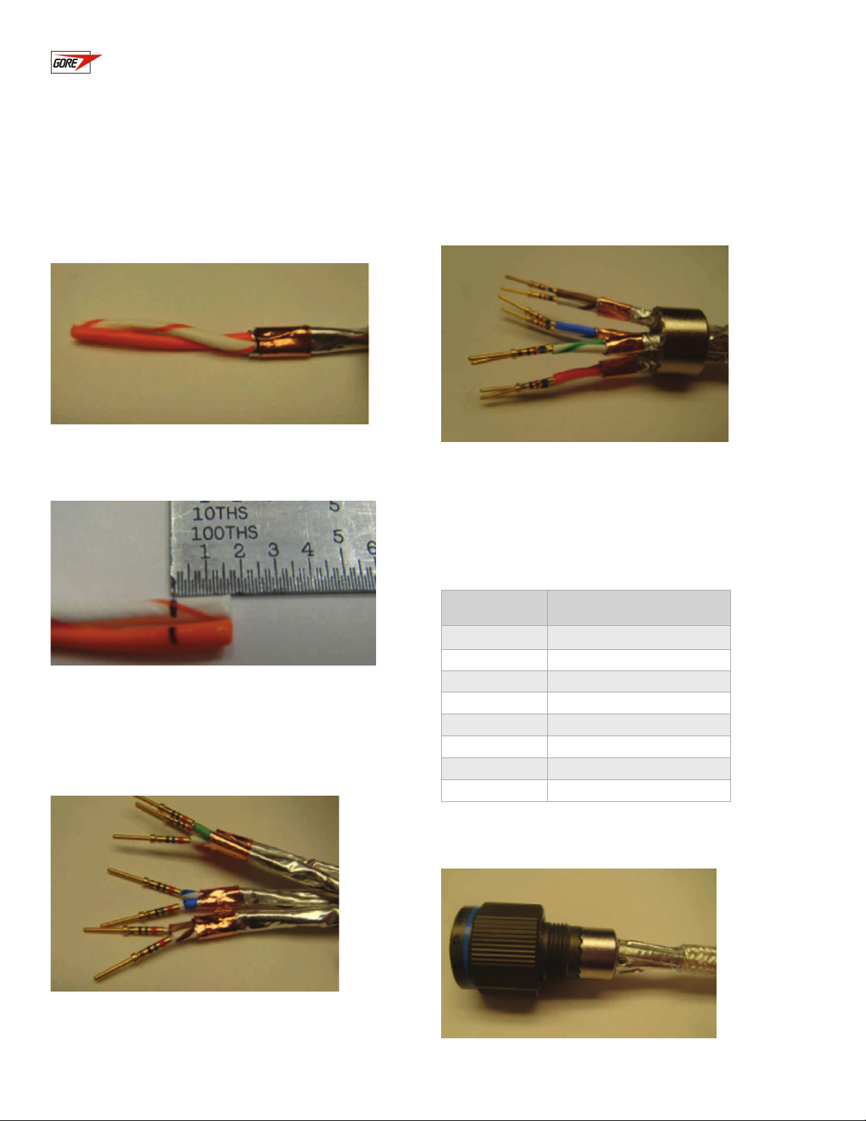
6. To identify the end for the pin connector, place a piece of tape
on the end in which the pairs rotate clockwise in order of
green orange blue brown (Figure 9).
Figure 9: Pairs configuration
at pin end
Figure 1: Needle nose pliers, scalpel, tweezer scissors, and hand strippers
Figure 3: Crimpers (M22520/2-01)
Figure 6: Clamp tool (Tie-Dex®II)
Figure 7: Braid brush
Figure 8: Probe/pick
Figure 2: Cutters
Figure 4: Socket positioner (K40) Figure 5: Pin positioner (K42)

2
Termination Instructions —
TE Connectivity®CeeLok FAS-X®
Connector System
GORE®Aerospace
Ethernet Cables
Figure 10: Sliding the backshell onto the cable
Figure 11: Marking the jacket
Figure 12: Slitting the cable jacket
Figure 14: Exposing the foil
Figure 15: Wrapping the foil
Figure 13: Exposing the braid
3. Measure and mark the jacket 0.5 inches from the end
of the cable (Figure 11).
4. Using a scalpel or scissors, slit the cable’s jacket from
its edge to the mark (Figure 12).
5. Using needle-nose pliers, gently pull the outer jacket down
the cable until you have exposed approximately 1.5 inches of
braid (Figure 13).
6. With your fingers, push the braid back over the cable to expose
approximately 1.5 inches of the foil (Figure 14).
7. Remove the white filler as far down as possible.
8. Cut a piece of copper or polyimide tape for each pair. Wrap
a piece of tape around the foil 0.5 inches from the end of
the cable (Figure 15). Try to use as small a piece of tape as
possible to minimize the buildup of material.
Terminating the Pin Connector (Termination A)
1. Slide one piece of the TAT onto the cable.
2. With the smallest end facing the cable, slide the backshell
(i.e., rubber grommet) and washers onto the cable (Figure 10).

3
Termination Instructions —
TE Connectivity®CeeLok FAS-X®
Connector System
GORE®Aerospace
Ethernet Cables
Figure 17: Marking each pair
Figure 18: Stripping the primaries
Figure 16: Tearing the foil
Figure 19: Inserting pairs through the metal sleeve
9. With cutters, cut the foil edge where it meets the tape.
Then, tear the foil along the tape edge (Figure 16).
10. Mark each pair 0.15 inch from the end of the cable (Figure 17).
11. Install the K42 positioner for the pin contact into the
M22520/2-01, and select setting 3. To prevent stray wire
strands during crimping, strip and crimp one primary at a
time using contacts from the kit (Figure 18).
12. Slide the metal sleeve over the pairs (Figure 19).
13. Using an insertion tool, insert each primary into the connector
according to the following table. It may be necessary to twist
the pairs to align them with the appropriate position in the
connector housing. If so, tighten the twist of the pair rather
than loosen the twist of the primary.
Pin Wire
1Green
2 Green/White
3Brown
4Brown/White
5Blue
6Blue/White
7Orange
8Orange/White
14. Slide the metal sleeve to connector housing (Figure 20).
Figure 20: Seating the metal sleeve

4
15. Gently move the braid toward the connector, and fold it
over the metal sleeve. Use a braid brush or pick to loosen
the braid as you fold it over the backshell (Figure 21).
Figure 21: Folding the braid over the backshell
Figure 22: Returning the jacket to the connector
Figure 23: Trimming the excess braid material
Figure 24: Placing the washers near the connector
Figure 25: Affixing the backshell
16. Push or slide the jacket back to the connector as
far as it will go, and trim the excess (Figure 22).
17. Trim the braid material to halfway over the metal
sleeve (Figure 23).
18. Slide the washers toward the connector (Figure 24).
19. Slide the backshell to the connector, and tighten it to
the manufacturer’s recommended torque value using the
appropriate torque fixture (Figure 25).
20. Perform all required testing. At a minimum, verify proper
wiring and continuity, and check for shorts. Local authorities
and end-users may require additional testing.
GORE®Aerospace
Ethernet Cables
Termination Instructions —
TE Connectivity®CeeLok FAS-X®
Connector System

5
Figure 26: Sliding the backshell onto the cable
Figure 27: Marking the jacket
Figure 28: Slitting the cable jacket
Terminating the Socket Connector (Termination B)
1. Slide one piece of the TAT onto the cable.
2. With the smallest end facing the cable, slide the backshell
(i.e., rubber grommet) and washers onto the cable (Figure 26).
3. Measure and mark the jacket 0.5 inches from the end of
the cable (Figure 27).
Figure 29: Exposing the braid
Figure 31: Wrapping the foil
Figure 30: Exposing the foil
4. Using a scalpel or scissors, slit the cable’s jacket from
its edge to the mark (Figure 28).
5. Using needle-nose pliers, gently pull the outer jacket down the
cable until you have exposed approximately 1.5 inches of braid
(Figure 29).
6. With your fingers, push the braid back over the cable to expose
approximately 1.5 inches of the foil (Figure 30).
7. Remove the white filler as far down as possible.
8. Cut a piece of copper or polyimide tape for each pair. Wrap a
piece of polyimide tape around the foil 0.7 inches from the end
of the cable (Figure 31). Try to use as small a piece of tape as
possible to minimize the buildup of material.
GORE®Aerospace
Ethernet Cables
Termination Instructions —
TE Connectivity®CeeLok FAS-X®
Connector System

6
Figure 32: Tearing the foil
Figure 33: Marking each pair
Figure 34: Stripping the primaries
Figure 34: Inserting pairs through the metal sleeve
9. With cutters, cut the foil edge where it meets the tape.
Then, tear the foil along the tape edge (Figure 32).
10. Mark each pair 0.15 inch from the end of the cable (Figure 33).
11. Install the K40 positioner for the socket contact into the
M22520/2-01, and select setting 3. To prevent stray wire
strands during crimping, strip and crimp one primary at a
time using contacts from the kit (Figure 34).
12. Slide the metal sleeve over the pairs (Figure 35).
13. Using an insertion tool, insert each primary into the connector
according to the following table. It may be necessary to twist
the pairs to align them with the appropriate position in the
connector housing. If so, tighten the twist of the pair rather
than loosen the twist of the primary.
14. Slide the inner metal sleeve to connector housing (Figure 36).
Pin Wire
1Green
2 Green/White
3Brown
4Brown/White
5Blue
6Blue/White
7Orange
8Orange/White
Figure 36: Seating the metal sleeve
GORE®Aerospace
Ethernet Cables
Termination Instructions —
TE Connectivity®CeeLok FAS-X®
Connector System

7
15. Gently move the braid toward the connector and fold it over
the metal sleeve (Figure 37). Use a braid brush or pick to
loosen the braid as you fold it over the backshell.
16. Push or slide the jacket back to the connector as far as it
will go, and trim the excess (Figure 38).
17. Trim the braid material to halfway over the inner
metal sleeve (Figure 39).
18. Slide the washers toward the connector (Figure 40).
Figure 37: Folding the braid over the backshell
Figure 38: Returning the jacket to the connector
Figure 39: Trimming the excess braid material
Figure 40: Placing the washers near the connector
19. Slide the backshell to the connector, and tighten it to
the manufacturer’s recommended torque value using the
appropriate torque fixture (Figure 41).
Figure 41: Affixing the backshell
20. Perform all required testing. At a minimum, verify proper
wiring and continuity, and check for shorts. Local authorities
and end-users may require additional testing.
GORE®Aerospace
Ethernet Cables
Termination Instructions —
TE Connectivity®CeeLok FAS-X®
Connector System

W. L. Gore & Associates
gore.com
GORE and designs are trademarks of W. L. Gore & Associates. © 2015 W. L. Gore & Associates, Inc. ACS-167-REF-US-NOV15
GORE®Aerospace
Ethernet Cables
TE Connectivity and CeeLok FAS-X are trademarks of the TE Connectivity LTD family of companies.
BAND-IT, Tie-Dex and Tie-Dex II are registered trademarks of BAND-IT IDEX, Inc.
Geo-Marine is a registered trademark of Glenair, Inc.
Termination Instructions —
TE Connectivity®CeeLok FAS-X®
Connector System
This manual suits for next models
1
Other GORE Cables And Connectors manuals
Popular Cables And Connectors manuals by other brands

Philips
Philips SWA3512 Specifications

Philips
Philips SWA4536W/10 user manual

Blackbird
Blackbird 44086 user manual

Siemens Energy
Siemens Energy SpecTRON 45 Installation & operation manual

TomTom
TomTom Curfer OBD manual

Gleason Reel
Gleason Reel Universal Cable Reel-Drive Drive UE32 Installation and maintenance instructions