GORE TE Connectivity CeeLok FAS-T User manual

1
Termination
Instructions
GORE®Aerospace
Ethernet Cables
TE Connectivity®CeeLok FAS-T®Connector System
The following procedures are based on Gore’s best practices
for terminating GORE®Aerospace Ethernet Cables with the TE
Connectivity®CeeLok FAS-T®Connector System for both plug and
receptacle versions. These procedures should be used as a guide
in conjunction with current connector manufacturing instructions.
Preparing the Cable and Parts
1. Gather the tools and materials required for assembly and
termination (Figures 1–9).
2. Verify that you have the correct parts for your assembly by
checking the part numbers for the connectors and the GORE®
Aerospace Ethernet Cables listed on drawing DDA0238.
3. Cut two 1.0-inch pieces of 0.50-inch thin-walled adhesive-
lined tubing (TAT).
4. Cut the cable to the desired assembly length minus 1.9
centimeters (cm) to allow for length of the connectors (i.e.,
1.3 cm for the plug connector and 0.6 cm for the receptacle
connector).
5. Print any labels required by the end-user, and slide the center
label onto the cable.
6. To identify the end for the receptacle connector, place a piece
of tape on the end in which the pairs rotate clockwise in order
of green orange blue brown (Figure 10).
Figure 10: Pairs configuration
at receptacle end
1 Gore recommends using copper foil tape instead of polyimide tape during termination
procedures because copper tape is easier to use and improves signal integrity.
Figure 1: Needle nose pliers, scalpel, tweezer scissors, and hand strippers
Figure 3: Crimpers (M22520/2-01)
Figure 5: Clamp tool (Tie-Dex®II)
Figure 7: Braid brush
Figure 8: Insertion/extraction tool (DHK 696)
Figure 9: Probe/pick
Figure 6: Copper foil tape1
(3M-3313)
Figure 2: Cutters
Figure 4: Positioner (K1850)

2
Termination Instructions —
TE Connectivity®CeeLok FAS-T®
Connector System
GORE®Aerospace
Ethernet Cables
Terminating the Plug Connector (Termination A)
1. Slide one piece of the TAT onto the cable.
2. Measure and mark the cable 1.0 inch from the plug end of
the cable (Figure 11).
Figure 11: Marking the cable
Figure 12: Slitting the cable jacket Figure 15: Marking each pair
Figure 13: Exposing the braid
Figure 16: Wrapping the pair
Figure 14: Exposing the foil
3. Using a scalpel or scissors, slit the cable’s jacket from its edge
to the mark (Figure 12).
4. Using needle-nose pliers, gently pull the outer jacket down
the cable until you have exposed approximately 2 inches of
braid (Figure 13).
5. With your fingers, push the braid back over the cable to expose
approximately 2 inches of the foil (Figure 14).
6. Remove the white filler as far down as possible.
7. Mark each pair 0.9 inch from the end of the cable (Figure 15).
8. Cut a 0.5-inch piece of copper or polyimide tape for each
pair of the cable. Wrap a piece around each pair at the mark
made in Step 7, making sure that the foil shield is as tight as
possible (Figure 16).

3
Termination Instructions —
TE Connectivity®CeeLok FAS-T®
Connector System
GORE®Aerospace
Ethernet Cables
Figure 18: Marking each primary
Figure 22: Stripping and crimping primaries
Figure 19: Stripping a primary Figure 20: Primaries that have been
stripped
Figure 17: Removing the foil edge
Figure 21: Marking a primary
9. With cutters, cut the foil edge where it meets the tape, and
tear the foil along the tape edge (Figure 17).
10. Mark each primary 0.8 inch from the end of the cable (Figure 18).
11. Use 22-gauge hand strippers to strip the outer layer of
dielectric off from the edge to the mark on each primary.
If the strippers do not give a clean cut, use your fingers or
tweezers to remove slug (Figures 19–20).
12. Mark each primary at 0.125 inch from the end (Figure 21).
13. Install the K1850 positioner for the pin contacts into the
M22520/2-01, and select setting 3. To prevent stray wire
strands during crimping, strip and crimp one primary at a time
(Figure 22).

4
Pin Wire
1Green
2 Green/White
3Brown
4Brown/White
5Blue
6Blue/White
7Orange
8Orange/White
14. Using an insertion tool, insert each primary into the connector
according to the following table (Figures 23–24):
Figure 23: Diagram of
pin positions Figure 24: Inserting primaries into the connector
15. Slide the braid back toward the plug. Using the braid brush or
pick, brush the braid until it fans over the knurled part of the
connector (Figure 25).
Figure 25: Brushing the braid
Figure 27: Marking the cable
Figure 28: Slitting the cable jacket
Figure 26: Returning the outer jacket
16. With your fingers or needle-nose pliers, push the outer jacket
as close as possible to the connector, and trim excess jacket
material (Figure 26).
Terminating the Receptacle Connector (Termination B)
1. Slide the other piece of the TAT onto the cable.
2. Measure and mark the cable 1.0 inch from the receptacle end
of the cable (Figure 27).
3. Using a scalpel or scissors, slit the cable’s jacket from its edge
to the mark (Figure 28).
GORE®Aerospace
Ethernet Cables
Termination Instructions —
TE Connectivity®CeeLok FAS-T®
Connector System

5
Figure 30: Exposing the foil
Figure 31: Marking each pair
Figure 29: Exposing the braid
Figure 32: Wrapping the pair
4. Using needle-nose pliers, gently pull the outer jacket down the
cable until you have exposed approximately 2 inches of braid
(Figure 29).
5. With your fingers, push the braid back over the cable to expose
approximately 2 inches of the foil (Figure 30).
6. Remove the white filler as far down as possible.
7. Mark each pair 0.9 inch from the end of the cable (Figure 31).
8. Cut a 0.5-inch piece of copper or polyimide tape for each pair
of the cable. Wrap a piece around each pair at the mark made
in Step 7, making sure that the foil shield is as tight as possible
(Figure 32).
Figure 33: Removing the foil edge
Figure 34: Marking each primary
9. With cutters, cut the foil edge where it meets the tape, and tear
the foil along the tape edge (Figure 33).
10. Mark each primary 0.8 inch from the end of the cable (Figure 34).
GORE®Aerospace
Ethernet Cables
Termination Instructions —
TE Connectivity®CeeLok FAS-T®
Connector System

6
Figure 38: Stripping and crimping primaries
Figure 41: Brushing the braid
Figure 37: Marking a primary
11. Use 22-gauge hand strippers to strip the outer layer of
dielectric off from the edge to the mark on each primary.
If the strippers do not give a clean cut, use your fingers or
tweezers to remove slug (Figures 35–36).
Figure 35: Stripping a primary Figure 36: Primaries that have been
stripped
12. Mark each primary at 0.125 inch from the end (Figure 37).
13. Install the K1850 positioner for the pin contacts into the
M22520/2-01, and select setting 3. To prevent stray wire
strands during crimping, strip and crimp one primary at a
time (Figure 38).
14. Using an insertion tool, insert each primary into the
connector according to the following table and diagram
(Figures 39–40):
Pin Wire
1Green
2 Green/White
3Brown
4Brown/White
5Blue
6Blue/White
7Orange
8Orange/White
Figure 39: Diagram of
pin positions
Figure 40: Inserting primaries into the
connector
15. Slide the braid back toward the plug. Using the braid brush
or pick, brush the braid until it fans over the knurled part of
the connector (Figure 41).
GORE®Aerospace
Ethernet Cables
Termination Instructions —
TE Connectivity®CeeLok FAS-T®
Connector System

7
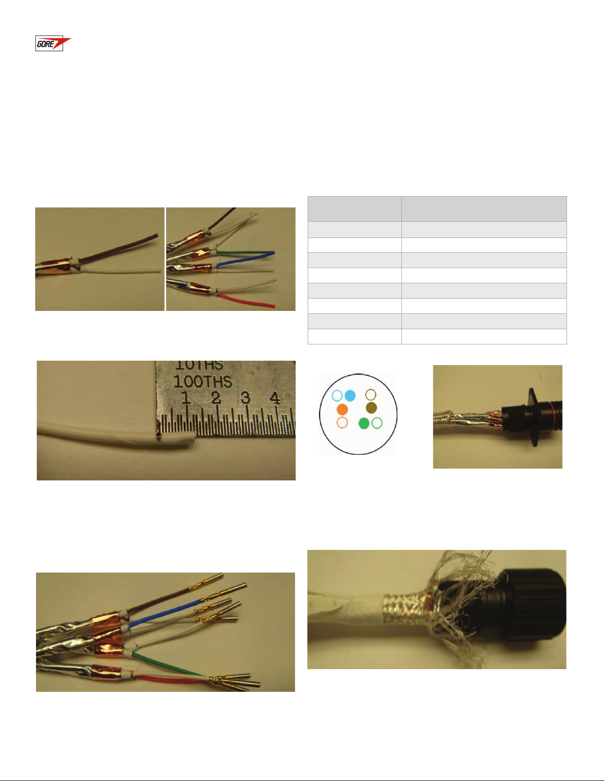
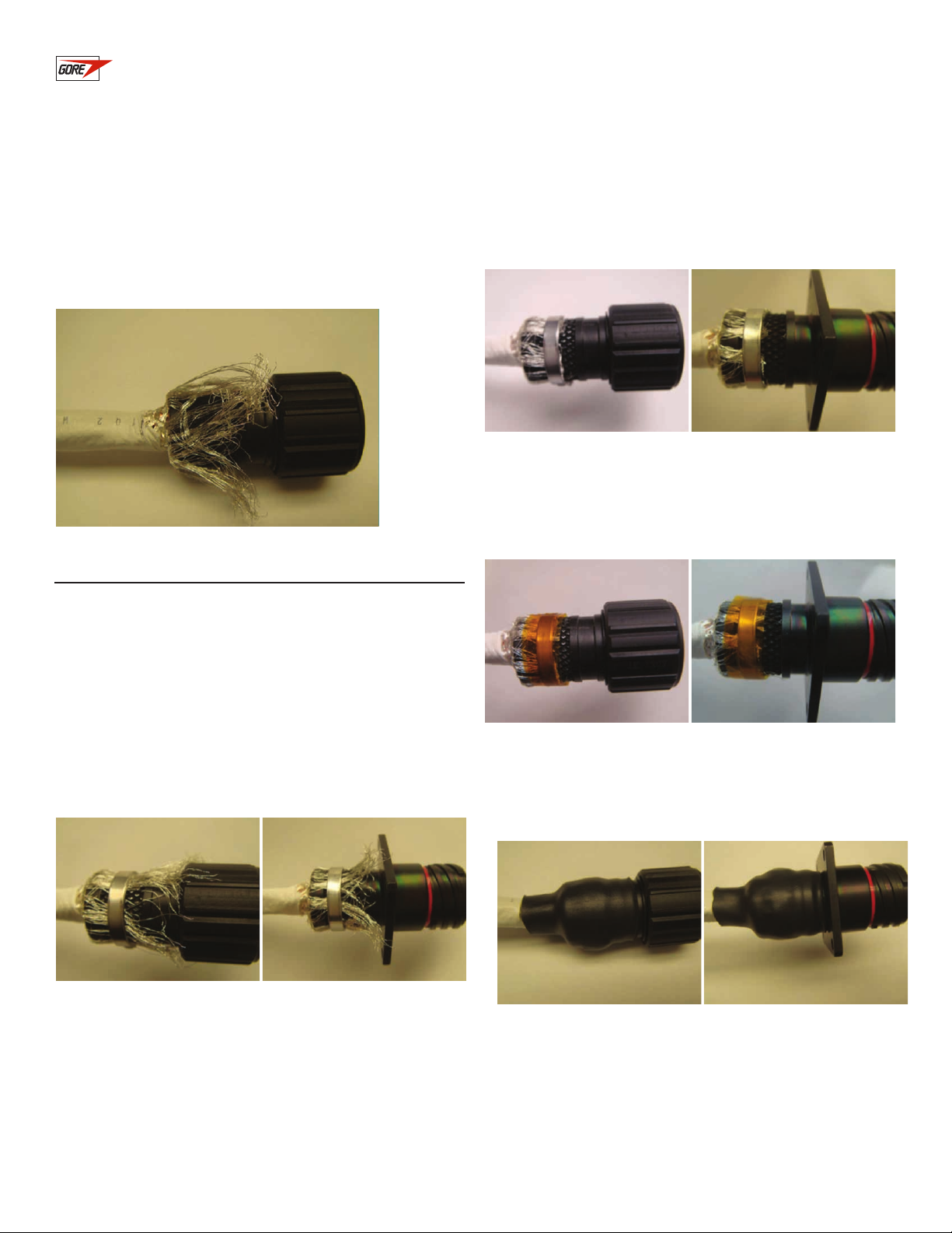
Figure 42: Returning the outer jacket
16. With your fingers or needle-nose pliers, push the outer
jacket as close as possible to the connector, and trim
excess jacket material (Figure 42).
Closing the Connectors
1. Perform all required in-process testing. At a minimum, verify
proper wiring and continuity, and check for shorts. Local
authorities and end-users may require additional testing.
2. Verify that the assembly length is accurate.
3. Brush out the braid again so that it lays flat against the
knurled section of the plug and the receptacle.
4. Using the Tie-Dex®II clamp tool, attach a Band-It®clamp to
the end of each connector (Figures 43–44).
Figure 43: Attaching Band-It to plug
Figure 49: Shrinking tubing on plug
Figure 45:Trimming excess braid on
plug
Figure 47: Taping the plug
Figure 44: Attaching Band-It to receptacle
Figure 50: Shrinking tubing on receptacle
Figure 46: Trimming excess braid on
receptacle
Figure 48: Taping the receptacle
5. Using cutters, trim off the excess braid (Figures 45–46).
6. Cut two pieces of 0.25-inch polyimide tape, and wrap it around
each Band-It at least twice (Figures 47–48). Be careful when
wrapping the tape, because the Band-It is very sharp.
7. Position the tubing so that it completely covers the band and
braid. Using a heat-gun, shrink the tubing on each connector
(Figures 49–50).
8. Perform all required testing. At a minimum, verify proper wiring
and continuity, and check for shorts. Local authorities and end-
users may require additional testing.
9. Using a heat-gun, shrink the center label, if appropriate.
GORE®Aerospace
Ethernet Cables
Termination Instructions —
TE Connectivity®CeeLok FAS-T®
Connector System

W. L. Gore & Associates
gore.com
GORE and designs are trademarks of W. L. Gore & Associates. © 2015 W. L. Gore & Associates, Inc. ACS-166-REF-US-NOV15
GORE®Aerospace
Ethernet Cables
TE Connectivity and CeeLok FAS-X are trademarks of the TE Connectivity LTD family of companies.
BAND-IT, Tie-Dex and Tie-Dex II are registered trademarks of BAND-IT IDEX, Inc.
Geo-Marine is a registered trademark of Glenair, Inc.
Termination Instructions —
TE Connectivity®CeeLok FAS-T®
Connector System
Other GORE Cables And Connectors manuals
Popular Cables And Connectors manuals by other brands

Xantech
Xantech XT-HDBT-SP14-4K-KIT Quick reference guide

Leuze
Leuze multiNet plus Master MA 30 Technical description

Wen
Wen 56421 instruction manual

Altera
Altera USB-Blaster user guide

Allen-Bradley
Allen-Bradley Kinetix 5500 installation instructions

CEAG
CEAG Cooper Crouse-Hinds GHG 57 Series operating instructions