OM-05171 60 SERIES
PAGE B - 2 INSTALLATION
c. Carefully read all tags, decals and markings
on the pump assembly, and follow the instruc
tions indicated.
d. Check all lubricant levels and lubricate as
necessary. Refer to LUBRICATION in the
MAINTENANCE AND REPAIR section of this
manual and perform duties as instructed.
e. If the pump and engine have been stored for
more than 12 months, some of the compo
nents or lubricants may have exceeded their
maximum shelf life. These must be inspected
or replaced to ensure maximum pump serv
ice.
f. Check to ensure the following standard
equipment items are included with the pump
assembly:
SPortable 6.5 gallon fuel tank complete with
quick‐connect fitting.
SSuction strainer.
SRubber foot mounting kit (must be
installed). To install feet, position flat wash
ers on capscrews, slide the capscrews
through the rubber feet and holes in the
base, and secure with the flanged hex nut.
If the maximum shelf life has been exceeded, or if
anything appears to be abnormal, contact your
Gorman‐Rupp distributor or the factory to deter
mine the repair or updating policy. Do not put the
pump into service until appropriate action has
been taken.
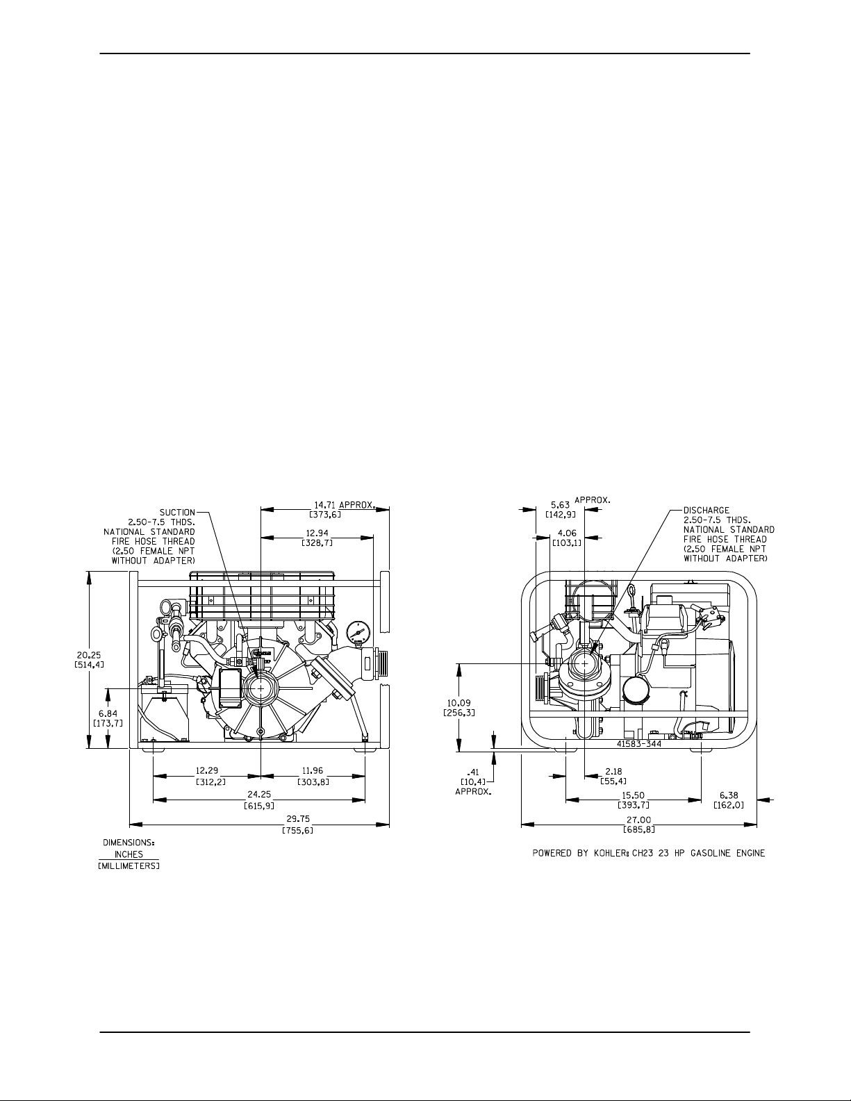
POSITIONING PUMP
This pump is designed to be very light‐weight and
portable. The total pump weight is approximately
240 pounds (109 kg), not including accessories
or engine fuel. Customer installed equipment such
as suction and discharge hoses must be removed
before attempting to lift.
Mounting
Locate the pump in an accessible place as close as
practical to the liquid being pumped. Level mount
ing is essential for proper operation.
The pump may have to be supported or shimmed
to provide for level operation or to eliminate vibra
tion.
To ensure sufficient lubrication and fuel supply to
the engine, do not position the pump and engine
more than 15_off horizontal for continuous opera
tion. The pump and engine may be positioned up
to 30_off horizontal for intermittent operation
only; however, the engine manufacturer should be
consulted for continuous operation at angles
greater than 15_.
SUCTION AND DISCHARGE PIPING
Pump performance is adversely effected by in
creased suction lift, discharge elevation, and fric
tion losses. See the performance curve and oper
ating range shown on Page E‐1 to be sure your
overall application allows pump to operate within
the safe operation range.
Materials
Either pipe or hose maybe used for suction and
discharge lines; however, the materials must be
compatible with the liquid being pumped. If hose is
used in suction lines, it must be the rigid‐wall, rein
forced type to prevent collapse under suction. Us
ing piping couplings in suction lines is not recom
mended.
Line Configuration
Keep suction and discharge lines as straight as
possible to minimize friction losses. Make mini
mum use of elbows and fittings, which substan
tially increase friction loss. If elbows are necessary,
use the long‐radius type to minimize friction loss.
Connections to Pump
Before tightening a connecting flange, align it ex
actly with the pump port. Never pull a pipe line into
place by tightening the flange bolts and/or cou
plings.
Lines near the pump must be independently sup
ported to avoid strain on the pump which could
cause excessive vibration, decreased bearing life,
and increased shaft and seal wear. If hose‐type
lines are used, they should have adequate support
to secure them when filled with liquid and under
pressure.
Gauges
Most pumps are drilled and tapped for installing
discharge pressure and vacuum suction gauges. If