Gotting HG G-19600ZA User manual

Preliminary Device Description HG G-19600ZA | English, Revision 02 | Date: 13.03.2018
2Overview
Summary
Characteristics of the magnet sensor HG G-19600ZA:
•Indoor / IP 54
•Digital magnetometer technology,
robust and maintenance free
•For axially polarized magnetic tape
(widths 50 mm), reading distance
60 mm
•Magnetic band easy to install
•Detection of the magnetic tape not
influenced by dirt on the track
•Display of the system status via 5 LEDs
•Three independent detection systems
for the recognition of turnoffs
•Turnoffs in the track can be selected via
digital inputs
•Analog outputs: Flux density Z (0 ... 10
VDC), flux density X (-10 ... +10 VDC)
•Digital output: Detection of a magnetic
tape in the reading area (+24 VDC, max.
20 mA)
•Avoid strong magnetic fields close to
the sensor, see section 3.2.1 on page 11
© 2018 Götting KG, errors and modifications reserved.
The Götting KG in D-31275 Lehrte has
a certified quality management system
according to ISO 9001.

Preliminary Device Description HG G-19600ZA | English, Revision 02 | Date: 13.03.2018
3Table of Contents
Contents
1 About this Document ............................................................................. 5
1.1 Function................................................................................................................................. 5
1.2 Symbols ................................................................................................................................. 5
2 Introduction............................................................................................. 7
2.1 Range of Use ........................................................................................................................ 7
2.2 Qualification of the Users................................................................................................. 7
2.3 Intended Use ........................................................................................................................ 7
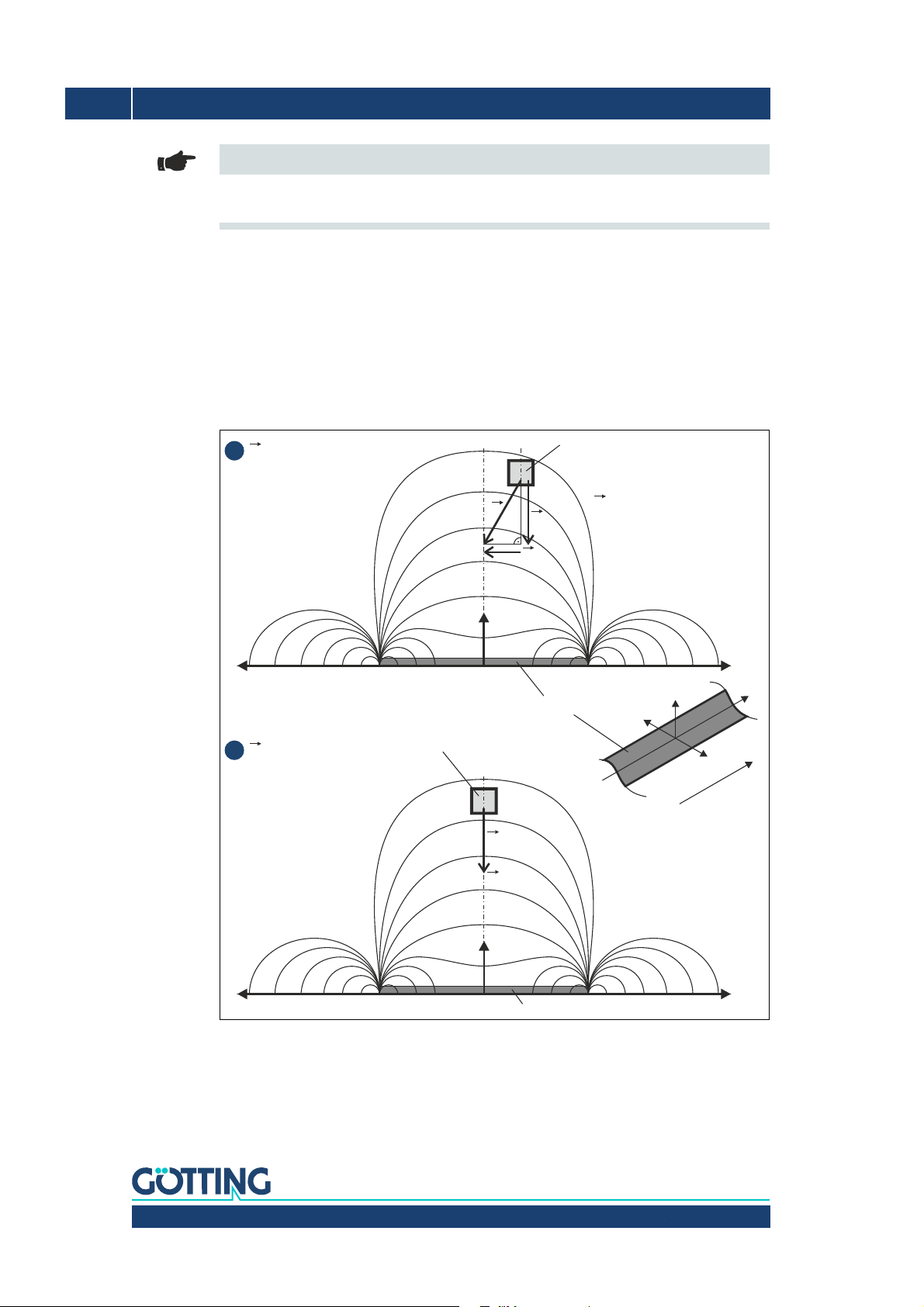
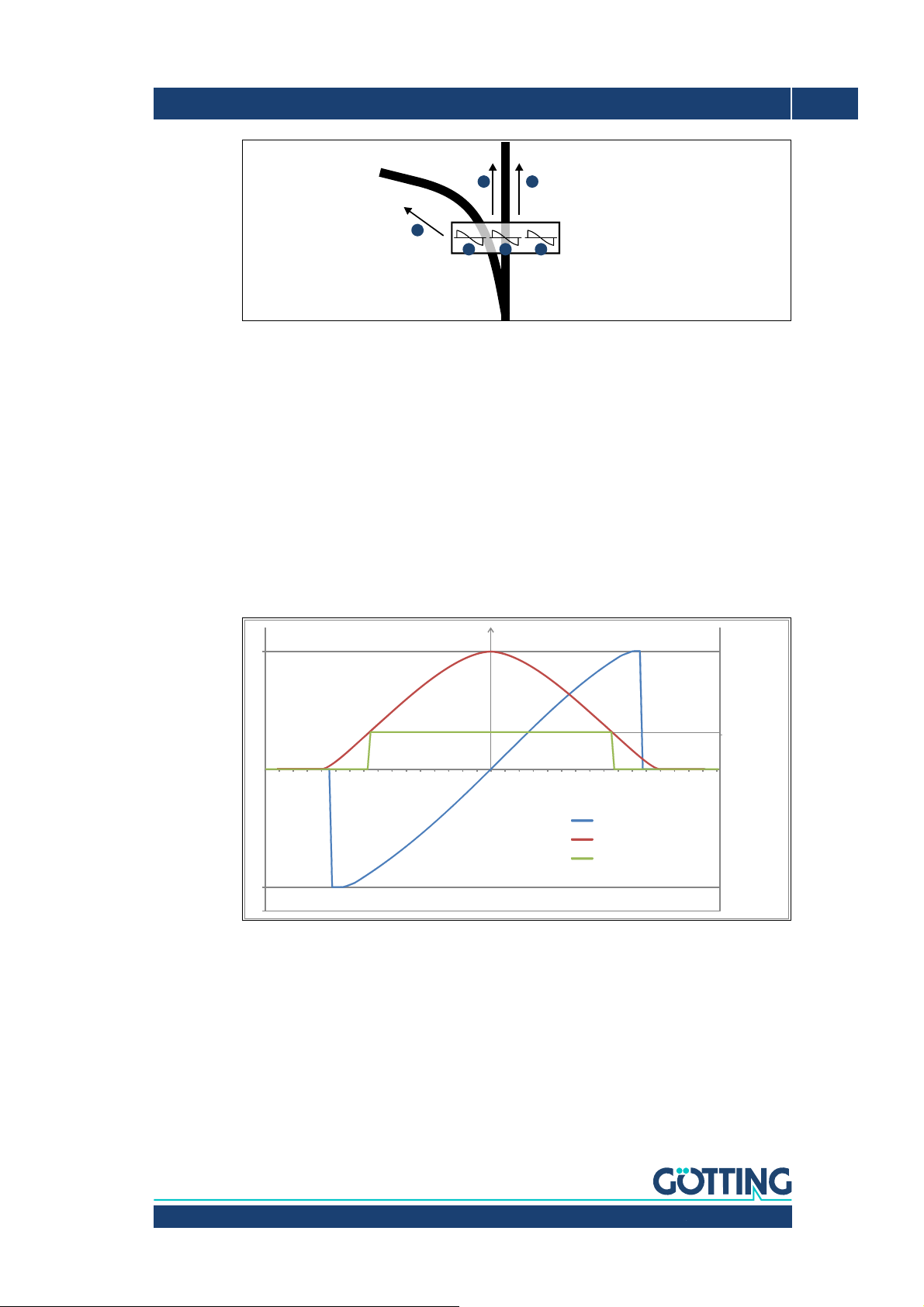
2.4 Functional Principle ........................................................................................................... 8
3 Mounting ............................................................................................... 10
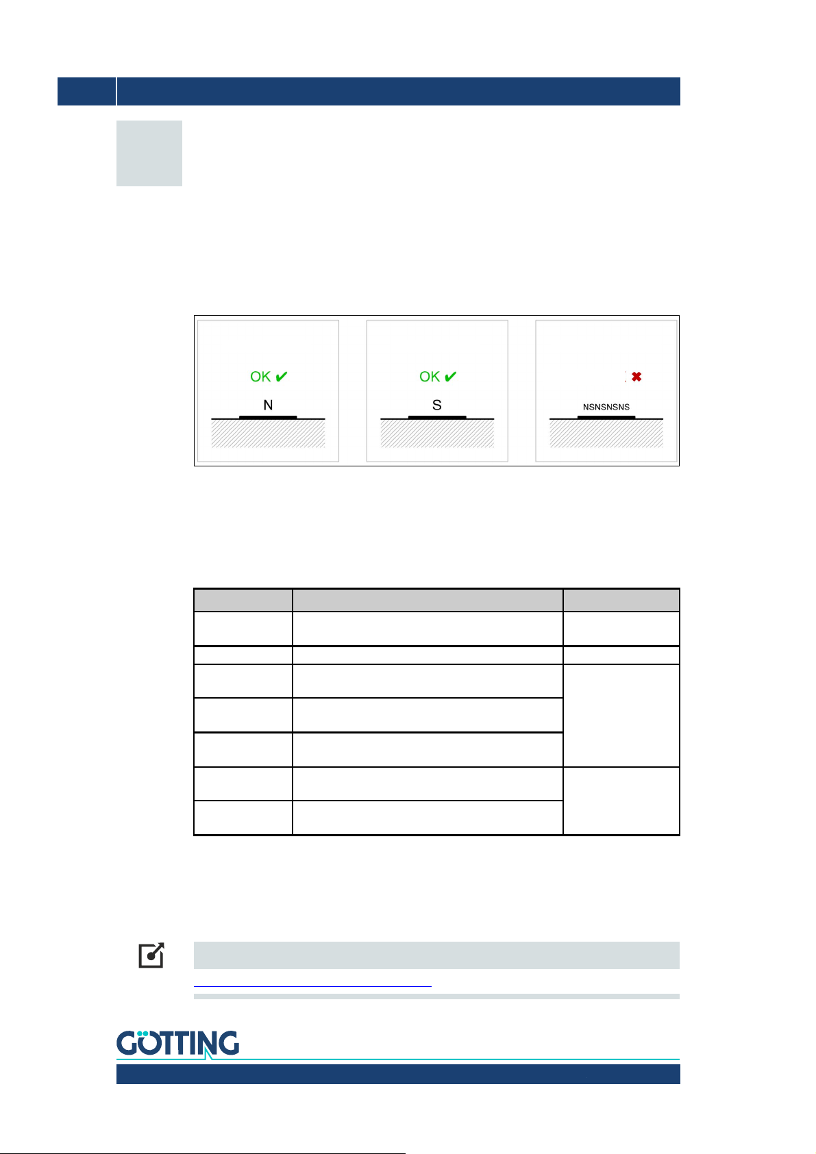
3.1 Magnetic Tape ...................................................................................................................10
3.1.1 Magnetic Tape Types ...................................................................................................................10
3.1.2 Magnetic Tape Installation .........................................................................................................10
3.2 Magnet Sensor ..................................................................................................................11
3.2.1 Requirements..................................................................................................................................11
3.2.2 Mounting on the Vehicle .............................................................................................................12
3.2.3 Connection Cable (assembled on one side) ..........................................................................13
4 Commissioning ..................................................................................... 14
4.1 Configuration of the Magnet Sensor ..........................................................................14
4.2 Compensation of Permanent Magnetic Interferences ..........................................16
4.2.1 Compensation of Static Magnetic Interferences .................................................................17
4.2.2 Deleting the Compensation........................................................................................................17
4.3 Automatic Calibration of the Track Detection .........................................................18
5 Hardware ............................................................................................... 19
5.1 LEDs ......................................................................................................................................19
5.2 Pin Assignment .................................................................................................................20
5.2.1 ST 1 Service / Configuration ......................................................................................................20
5.2.2 ST 2 Operation................................................................................................................................20
5.2.3 Digital Inputs Turnoff Selection ................................................................................................21
5.3 Turning off from the Main Track..................................................................................21
6 Software ................................................................................................22
6.1 Switch-On Behavior .........................................................................................................22
6.2 Connection to a PC via the Serial Interface .............................................................22
6.3 Terminal Program .............................................................................................................22
6.4 Service Program................................................................................................................23
6.4.1 (1) CSV Output................................................................................................................................24
6.4.2 (2) Settings ......................................................................................................................................26
6.4.3 (C) calibration settings .................................................................................................................27
6.4.4 (3) test monitor...............................................................................................................................28
6.4.5 (4) RAW data monitor...................................................................................................................29
6.4.6 Software Update (Firmware)......................................................................................................30
7 Maintenance.......................................................................................... 31

Preliminary Device Description HG G-19600ZA | English, Revision 02 | Date: 13.03.2018
4Table of Contents
8 Technical Data ...................................................................................... 32
9 List of Figures....................................................................................... 33
10 List of Tables ........................................................................................ 34
11 Index ...................................................................................................... 35
12 Copyright and Terms of Liability ........................................................ 37
12.1 Copyright ............................................................................................................................ 37
12.2 Trade Marks and Company Names............................................................................. 37

Preliminary Device Description HG G-19600ZA | English, Revision 02 | Date: 13.03.2018
5About this Document – Chapter 1
1About this Document
1.1 Function
This device description contains information regarding the correct mounting, electric instal-
lation, commissioning and maintenance of the magnet sensor HG G-19600ZA for the tech-
nical personnel of a manufacturer who wants to integrate the magnet sensor into an auto-
mated guided vehicle (AGV).
This device description does not contain information regarding the usage of the superordi-
nate system, e.g. the automated guided vehicle (AGV). For this information consult the doc-
umentation of the vehicle manufacturer resp. the operator of a facility.
This device description applies to devices with firmware version V0.40 and higher (see Fig-
ure 15 on page 23 on how to detect which firmware version your device has).
1.2 Symbols
The following symbols and formatting are used in Götting documentations:
Note
Indicates technical information that should be followed when using the device.
ATTENTION!
Indicates dangers that may lead to damages or the destruction of the device.
BEWARE!
Indicates dangers that may lead to injuries or severe damage of property.
WARNING!
Indicates dangers that may lead to injuries, potentially with loss of life, or severe damage of
property.
Tip
Indicates information that makes handling of the device easier.

Preliminary Device Description HG G-19600ZA | English, Revision 02 | Date: 13.03.2018
6Chapter 1 – About this Document
Link
Indicates additional information in the internet, e.g. on our homepage www.goetting-
agv.com. Those links are clickable in the PDF version of this documentation.
Program texts and variables are indicated through the use of a fixed width
font.
Whenever the pressing of letter keys is required for program entries, the required
etter eys are indicated as such (for any programs of Götting KG small and capital
letters are equally valid).

Preliminary Device Description HG G-19600ZA | English, Revision 02 | Date: 13.03.2018
7Introduction – Chapter 2
2Introduction
2.1 Range of Use
•The magnet sensor is intended for indoor usage.
•On the surface of the track roadway compatible magnetic tape is layed. Alternatively
a magnetic bar can be embedded into the roadway (see section 3.1 on page 10).
•The magnetic sensor is installed so that its underside faces the roadway and meets
the nominal reading distance towards the surface of the magnetic tape (see section
3.2 on page 11).
2.2 Qualification of the Users
The personnel intended to operate the magnetic sensor
•has been provided with this documentation.
•is familiar with the functionality of the magnetic sensor.
•is trained sufficiently in mounting and configuring the magnet sensor and qualified to
perform those tasks.
•knows the risks posed by driverless vehicles and is trained in the necessary safety
precautions to assess the safe operational state of the system.
All personnel in the area of influence of the magnetic sensor is instructed regarding the kind
of the vehicle and the risks resulting from the driverless operation.
2.3 Intended Use
The magnet sensor HG G-19600ZA is intended for the track guidance of automated guided
vehicles (AGV) along magnetic tape. The sensor detects the magnetic field above magnetic
tape in vertical and horizontal direction and thus continually determines the actual deviation
from the center of the track (center of the magnetic tape). The deviation is output as analog
voltages.
WARNING!
The magnet sensor does not contain functionality to detect obstacles or persons in front of
a vehicle! The vehicle manufacturer has to include suitable safety equipment.
BEWARE!
Interferences as specified in section 3.2 on page 11 may lead to inaccurate outputs whereby
the vehicle may leave the track. The vehicle manufacturer has to include functionality to de-
tect this and stop the vehicle if needed. As an aid the digital output DOUT1 track detect can
be used, see section 5.2.2 on page 20.

Preliminary Device Description HG G-19600ZA | English, Revision 02 | Date: 13.03.2018
8Chapter 2 – Introduction
Note
In case the magnetic sensor is used for other purposes than specified above or is modified
all warranties against the Götting KG are null and void.
The magnet sensor is only used according to section 2.1 on page 7. The magnet sensor is
only mounted, configured, commissioned, operated, maintained and dismounted by per-
sonnel according to section 2.2 on page 7.
2.4 Functional Principle
The sensor is based on digital magnetometer technology for the detection of the magnetic
field above the magnetic tape.
Figure 1 Detection of the magnetic field
The sensor has three independent detection systems. Via two digital inputs one of two
tracks can be chosen dynamically. Thus the sensor can detect junctions and follow turnoffs
(also see 5.3 on page 21).
N
N
Magnetic tape
roadway
roadway
Magnet sensor
element
Lines of identical flux
density above the
magnetic tape
Magnet sensor
element
Magnetic tape
Direction
of travel
B
Z
B
X
B
ZY
Z
Z
X
+X
+X
-X
-X
B=max
Z
S
S
S
S
B=0
X
B >0
X
Deviation to the
right side.
B =0
X
No deviation.
The magnet sensor is
positioned centrical
above the magnetic
tape.
1
1
B = Flux density

Preliminary Device Description HG G-19600ZA | English, Revision 02 | Date: 13.03.2018
9Introduction – Chapter 2
Figure 2 Three detection systems for the recognition of junctions
Five LEDs show the operational state (PWR), error state (ERR) and a detected track under-
neath the independent systems (TR1, TR2, TR3).
Via two analog outputs the deviation from the track and the actual level of the magnetic
field are output. Additionally a detect signal is generated when a magnetic tape is detected
underneath the sensor.
The detection range depends on the mounting height of the sensor and the type of the mag-
netic tape. As shown in Figure 1 above the sensor detects the deviation X from the center
of the track by measuring the horizontal magnetic flux density. The higher the deviation the
higher the output analog voltage.
Figure 3 shows the signals of the outputs (AOUT 1, AOUT 2, Detect) when moving the sen-
sor in X direction above the magnetic tape (crosswise to the direction of travel).
Figure 3 Voltage curves of the analog outputs (idealized diagram)
1
1
2
2
3
3
Magnet sensor with three
Magnetic tape
track with junction
detection systems for the recognition
of junctions
(there may only ever be max. two
tracks simultaneously underneath the
magnet sensor)
‐10
10
‐80 ‐75 ‐70 ‐65 ‐60 ‐55 ‐50 ‐45 ‐40 ‐35 ‐30 ‐25 ‐20 ‐15 ‐10 ‐5 0 5 10 15 20 25 30 35 40 45 50 55 60 65 70 75 80
AOUT1(X)
AOUT2(Z)
Detect
Detect switches
to +24 VDC
Voltage curves AOUT1 and AOUT2 [VDC]
Deviation of the
sensor from the
center of the
magnetic tape
[mm]

Preliminary Device Description HG G-19600ZA | English, Revision 02 | Date: 13.03.2018
10 Chapter 3 – Mounting
3Mounting
3.1 Magnetic Tape
For the operation of the magnet sensor HG G-19600ZA axially polarized magnetic band is
to be used. The direction of the polarization can be configured s. Figure 19 on page 26). The
polarization has to be identical for a whole facility.
Figure 4 Supported and unsupported magnetization of the magnetic tape
3.1.1 Magnetic Tape Types
Götting offers suitable magnetic tapes. Magnetic tape is sticked to the ground. Alternatively
embedded magnetic bar can be used that is layed in a groove cut into the ground. Götting
magnetic tapes always have the north pole on the top. The following elements are available:
3.1.2 Magnetic Tape Installation
The installation of both the magnetic tape and the embedded magnetic bar is specified in
a separately available document that you can download at the following address:
Link
http://goetting-agv.com/components/19600
Order no. Description Notes
HW MAT00003 Magnetic tape, self-adhesive, on a roll
W x H 50 x approx. 1,2 mm
Roll, length 15.2 m
HW MAT00004 Embedded magnetic bar, W X H 6 x 10 mm quote length
HW MAT00005 Magnetic tape, self-adhesive curve segment
30osegment of circle, radius 600 mm
Curve segments
HW MAT00006 Magnetic tape, self-adhesive curve segment
30osegment of circle, radius 800 mm
HW MAT00007 Magnetic tape, self-adhesive curve segment
30osegment of circle, radius 1,000 mm
HW MAT00008 Magnetic junction, branch to the right, self-adhe-
sive, radius 1,000 mm
Junction segments
HW MAT00009 Magnetic junction, branch to the left, self-adhe-
sive, radius 1,000 mm
Table 1 Order numbers magnetic tape
(default) (configurable)
multipolar magnetizationaxial magnetization axial magnetization
not OK

Preliminary Device Description HG G-19600ZA | English, Revision 02 | Date: 13.03.2018
11Mounting – Chapter 3
3.2 Magnet Sensor
3.2.1 Requirements
ATTENTION!
Additional magnetic fields close to the magnet sensor can affect the system characteristics!
External magnetic fields with a field strength below the Earth‘s magnetic field do not influ-
ence the magnet sensor. For stronger fields the strength and position of the field determine
whether the magnet sensor is affected or can even be configured to compensate the influ-
ence. Fields that asymmetrically influence from a certain direction (left or right) or only oc-
cur at certain points of the course are harder to compensate. Generally interferences should
be minimized so that the magnet sensor can detect the track reliably. Therefore:
Figure 5 Areas around sensor and tape that need to be free of ferromagnetic materials
– An area of 100 mm around the sensor should be free of ferromagnetic materials.
Those divert the magnetic field and distort the readings. Similarly an area with a
diameter of approximately the nominal reading height around the magnetic tape
should be free of ferromagnetic materials.
– Around the sensor and the magnetic tape there may be no additional magnetic fields
(permanent magnets, electromagnets, electrical wires, etc.). How much the readings
are disturbed by interferences depends on the field strength.
– Electric motors have to be sufficiently shielded.
Tip
Interferences from the vehicle occur permanently, interferences along the track temporarily.
Permanent interferences can sometimes be compensated with offsets (see 6.4.2 on page
26). Constant magnetic interferences (e. g. brakes that are released electromagnetically)
can, starting with firmware version 0.45, be compensated, see section 4.2 on page 16.
100
100
100
356
100
100
Front view
Vehicle body
Roadway Magnet
tape
Magnet
sensor
Side view
‚metal-free‘
areas around
sensor and magnet
tape without
ferromagnetic
materials
Roadway
Magnet
sensor
Nominal
reading dist.
Nominal
reading distance
optional
distance
Vehicle
body
piece
(example)

Preliminary Device Description HG G-19600ZA | English, Revision 02 | Date: 13.03.2018
12 Chapter 3 – Mounting
Note
Interferences along the track have to be avoided e.g. by moving the magnetic track or by
shielding the source.
3.2.2 Mounting on the Vehicle
Figure 6 Casing dimensions and mounting drill holes of the magnet sensor
The magnet sensor has two drill holes with a diameter of 5 mm each with which it can be
mounted by putting screws through the holes. We recommend the usage of non-mag-
netizable VA screws. The drill holes have a distance of 140 mm to each other (center of
hole <—> center of hole). The magnet sensor is to be mounted diagonally to the direction
of travel with the connectors facing upwards (first sketch in Figure 6 above). The recom-
mended reading height is 60 mm from the bottom edge of the casing to the magnetic tape.
Note
Around the sensor there has to be an area free of ferromagnetic materials. Thus the sensor
usually can‘t be mounted directly onto the body of the vehicle. We recommend using a
mounting bracket or mounting plate, e.g. made from Aluminium or acrylic glass (e.g. Plexi-
glas®), see Figure 7 below.
Direction of
travel
Bottom edge
of the casing
M12 x 1 circular connector
8 pin (male)
M12 x 1 circular connector
5 pin (male)
Mounting
drill holes

Preliminary Device Description HG G-19600ZA | English, Revision 02 | Date: 13.03.2018
13Mounting – Chapter 3
Figure 7 Possible mounting pos. for the magnet sensor when using an optional distance piece
Tip
If the magnet sensor has to be mounted side-inverted (aka backwards) the output voltages
for the left and right deviations may be interchanged compared to what the vehicle control
expects. In this case the output voltage AOUT1 can be inverted inside the sensor, see 6.4.2
on page 26.
3.2.3 Connection Cable (assembled on one side)
Connect the sensor to the vehicle control. For this the connectors ST 1 and ST 2 are used.
The assignment of the pins is shown in section 5.2 on page 20. The following optional cable
extensions can be used.
Order no. Description
HW CAB00001 Cable PUR, 5m with one M12 angle coupling, 5 pin, A coded,
one end open
HW CAB00007 Cable PUR, 5m with M12 angle coupling, 8 pin, A coded,
one end open
Table 2 Accessories / cable extensions
Magnet tape
Roadway
Optional
Magnet sensor
Vehicle body
Direction of travel
distance piece
(material non
ferro-magnetic)

Preliminary Device Description HG G-19600ZA | English, Revision 02 | Date: 13.03.2018
14 Chapter 4 – Commissioning
4Commissioning
The sensor is pre-configured to detect a single track without turnoffs. For this ap-
plication it may be sufficient to install the sensor and connect it to the vehicle control. We
recommend to always connect it to a PC and configure it as shown below to minimize in-
terferences. If more than one track is to be detected and if there are turnoffs in the driving
course then the configuration as shown below has to be performed.
For the commissioning configuration the serial interface in connector ST 1 is used. Connect
ST 1 to a PC as shown in section 6.2 on page 22. Then start a compatible terminal program
with ANSI emulation (see section 6.3 on page 22). Then you can use the service program
that runs inside the magnet sensor (section 6.4 on page 23).
Note
For the following explanations we assume that your sensor is running with its default con-
figuration. If needed the default settings can be restored in the settings menu, see section
6.4.2 on page 26.
4.1 Configuration of the Magnet Sensor
The goal of the configuration is the reliable recognition of magnetic tracks. For this
the thresholds for the detection of one (resp. two) tracks have to be adjusted. The detection
of two tracks is necessary if there are to be junctions in the track. A track is detected when
the magnetic flux density is above the set threshold. The track detection has an internal
switching delay of 2 % so that it does not react too sensitively in border areas. For the com-
missioning the following menus and subitems of the service program are used:

Preliminary Device Description HG G-19600ZA | English, Revision 02 | Date: 13.03.2018
15Commissioning – Chapter 4
Figure 8 Commissioning: Menus of the service program
Meaning of the highlighted parameters:
•track polarity in settings menu: Polarity of the magnetic tape
•sensitivity in settings menu: Sensitivity of the detection of a magnetic track, threshold
value in milliTesla (mT)
•sen. two tracks in settings menu: Sensitivity of the detection of two magnetic tracks.
For applications without junctions set to maximum value 4.
•sum of flux density in raw data menu: Flux density of a magnetic tape underneath the
sensor
Tip
When using one of the magnetic tapes listed in section 3.1.1 on page 10 (HW MAT00003,
HW MAT00008 and HW MAT00009) the threshold sen. two tracks for two magnetic tracks
can be set according to the following table:
Reading height [mm] 50 60 70 80 90 100
sen. two tracks [mT] 0.8 0.64 0.5 0.4 0.32 0.275
Table 3 Thresholds for two magnetic tracks with standard magnetic tapes
HG19600 Serialnumber: 999999 Firmwareversion: V0.45
system monitor
__ __
| | | |
---------------------------------
| HG 19600 O O X O X |
| |
---------------------------------
X
next turn: STRAIGHT
position track: 7.500
(L) left
(R) right
(S) straight
error: 0x00 (D) digital input
(1) CSV Output
(2) settings
(3) testmode
(4) raw data
Status: DIN:00 DOUT:0 AOUT1(X): 7.5V AOUT2(Z): 7.6V
HG 19600 Serialnumber: 999999 Firmwareversion: V0.45
settings
Range:
(1) track polarity : north
(3) sensitivity : 0.200 [mT] 0.01 .. 2
(4) sen. two tracks: 0.800 0.1 .. 4
AOUT1 (X)
(5) amplitude : 10.00 [V] 2.5 .. (10 - offset)
(6) offset : 0.00 [V] 0 .. (10 - amplitude)
(7) invert output : NO
(H) hold analog output when detect is lost: NO
AOUT2 (Z)
(8) amplitude : 10.00 [V] 0 .. 10
(9) multiplier : 1.00 0 .. 10
(C) calibration
(D) load default settings
(F) firmware update
(ESC) QUIT
HG 19600 Serialnumber: 999999 Firmwareversion: V0.45
RAW data monitor
__ __
| | | |
---------------------------------
| HG 19600 O O O O X |
| |
---------------------------------
system 3 system 2 system 1
X -0.015 [mT] 0.011 [mT] 0.028 [mT]
Y -0.068 [mT] -0.041 [mT] -0.060 [mT]
Z 0.067 [mT] 0.066 [mT] 0.040 [mT]
track No No No
detect
sum of flux density: 0.231
(ESC) QUIT
Status: DIN:00 DOUT:0 AOUT1(X): 0.0V AOUT2(Z): 7.2V
Key 2
Key 4
Back with ESCBack with ESC
Main menu

Preliminary Device Description HG G-19600ZA | English, Revision 02 | Date: 13.03.2018
16 Chapter 4 – Commissioning
If there are problems detecting the track or when the working conditions are different we
recommend the following configuration sequence:
1. Configure the polarity of the magnetic tape (track polarity in settings menu). Default
for Götting magnetic tape or embedded magnetic bar: North.
2. Place the sensor centered above a piece of the used magnetic tape (default reading
height 60 mm). The piece should be long enough so that at least 10 cm protrude
behind and in front of the sensor.
3. Switch to the menu raw data and write the shown sum of flux density down. Then
switch to the settings menu and configure the sensitivity to be approx. one fifth of the
sum of flux density.
4. Switch to the main menu and move the sensor diagonally to the magnetic tape.
Check that the track is reliably detected even when it reaches the lateral edges of the
magnet sensor. Optionally the sensitivity in the settings menu has to be reduced if the
track is not detected in the border areas.
5. If the turnoff function is to be used the threshold sen. two tracks has to be config-
ured. Table 3 above shows typical values when Götting magnetic tape is used. Typi-
cally the threshold for the detection of two tracks is about three times the value for
one track. If the turnoff function is not needed (because there are no junctions in the
track) sen. two tracks should be set to its maximum value of 4. A good starting point
for the threshold for detection of two tracks is three times the limit for one track.
6. In order to test the threshold for two tracks place two pieces of magnetic tape under-
neath the sensor so that the left edge of the left tape should be directly underneath
the left edge of the sensor, the right edge of the right tape should match the right
edge of the sensor. Now when the digital inputs are switched (left, right, straight; via
the vehicle control, see 5.2.3 on page 21, or via the manual controls in the main menu
of the service program, see Figure 15 on page 23) two magnetic tapes should be
detected.
4.2 Compensation of Permanent Magnetic Interferences
ATTENTION!
Only static interferences can be compensated! The source of the interferences has to move
together with the magnet sensor and its strength may not change.
ATTENTION!
There is currently no possibility to enable or disable the compensation during operation! If
there is e.g. an electromagnetic brake that emits interferences when activated but emits no
interferences when it is inactive this can not be dynamically compensated. If a permanent
compensation would be set for the possible interferences the output of the magnet sensor
would be off by the scope of the compensation whenever the brake is inactive.

Preliminary Device Description HG G-19600ZA | English, Revision 02 | Date: 13.03.2018
17Commissioning – Chapter 4
ATTENTION!
The compensation of interferences limits the range of the magnetic field that can be used
for the track detection! The magnetic field and the compensated interferences together
have to fit inside the maximum detection range of the magnet sensor.
4.2.1 Compensation of Static Magnetic Interferences
Figure 9 Commissioning: Compensation of static magnetic interferences
Take the following steps:
1. Mount the magnet sensor at the desired mounting position on the AGV.
2. In menu Settings choose the option Calibration.
3. Use menu entry calibrate for static magnetic field.
4. Deactivate the interferences.
5. Confirm with continue. the sensor measures the magnetic field in its surround-
ings.
6. Turn the interferences on. Don‘t move the sensor/vehicle while doing so.
7. Confirm with continue. The sensor measures the magnetic field in its surround-
ings and calculates the amount of the interferences.
8. The calculated interferences are shown in the menu and will be subtracted from the
sensor‘s raw data.
4.2.2 Deleting the Compensation
1. In menu Settings choose the option Calibration.
2. Use menu entry delete static magnetic field compensation. The parameters for the
static compensation are deleted and no longer used.
HG 19600 Serialnumber: 999999 Firmwareversion: V
calibration settings
compensated magnetic field:
system 3 system 2 system 1
0,001 [mT] -0.021 [mT] -0.059 [mT]
-0,046 [mT] -0.054 [mT] -0.044 [mT]
0,013 [mT] 0.019 [mT] 0.022 [mT]
(1) calibrate for track detection
(2) calibrate for static magnetic field
(3) delete static magnetic field compensation
(ESC) QUIT
HG 19600 Serialnumber: 999999 Firmwareversion: V0.45
calibration settings
compensated magnetic field:
system 3 system 2 system 1
0.000 [mT] 0.000 [mT] 0.000 [mT]
(1) calibrate for track detection
(2) calibrate for static magnetic field
(3) delete static magnetic field compensation
(ESC) QUIT
HG 19600 Serialnumber: 999999 Firmwareversion: V0.45
calibration settings
compensated magnetic field:
system 3 system 2 system 1
0.000 [mT] 0.000 [mT] 0.000 [mT]
reading earth magnetic field...
please TURN OFF static field
(1) continue
(ESC) abourt
HG 19600 Serialnumber: 999999 Firmwareversion:
calibration settings
compensated magnetic field:
system 3 system 2 system 1
-0.000 [mT] -0.000 [mT] 0.000 [mT]
-0.000 [mT] 0.000 [mT] 0.000 [mT]
-0.000 [mT] -0.000 [mT] 0.000 [mT]
reading static magnetic field...
please TURN ON static filed
(1) continue
(ESC) abourt
Key 2 Key 1
Key 1
Beispielwerte

Preliminary Device Description HG G-19600ZA | English, Revision 02 | Date: 13.03.2018
18 Chapter 4 – Commissioning
4.3 Automatic Calibration of the Track Detection
In order to make it easier to set the thresholds starting with firmware version 0.45 it is pos-
sible to use the automatic configuration. In order to do so place the magnet sensor centered
above the magnetic track, then start the calibration (see below). It is still possible to manu-
ally set the parameters or to change the parameters found during the automatic calibration.
Note
If static interferences are compensated (see above) the interferences have to be present
during the automatic calibration since they are subtracted from the measured field.
Figure 10 Commissioning: Automatic calibration
Take the following steps:
1. Place the magnet sensor in the desired height centered above a single magnetic
track.
2. In menu Settings choose the option Calibration.
3. Use menu entry calibrate for track detection.
4. If the compensation from section 4.2 on page 16 is in use make sure that the interfer-
ences are present.
5. Confirm with continue that the sensor is placed centered above a single track.
6. The following parameters are automatically configured: sensitivity, sen. two tracks,
AOUT2 multiplicator.
HG 19600 Serialnumber: 999999 Firmwareversion: V0.45
calibration settings
compensated magnetic field:
system 3 system 2 system 1
0.000 [mT] 0.000 [mT] 0.000 [mT]
(1) calibrate for track detection
(2) calibrate for static magnetic field
(3) delete static magnetic field compensation
(ESC) QUIT
HG 19600 Serialnumber: 999999 Firmwareversion: V0.45
calibration settings
compensated magnetic field:
system 3 system 2 system 1
0.000 [mT] 0.000 [mT] 0.000 [mT]
reading magnetic track...
please TURN ON static field if static field is compansated
please PLACE one track under the center of the sensor
(1) continue
(ESC) abourt
Key 1
Key 1, to
perform
calibration

Preliminary Device Description HG G-19600ZA | English, Revision 02 | Date: 13.03.2018
19Hardware – Chapter 5
5Hardware
5.1 LEDs
There are 5 LEDs to control the sensor‘s function.
Figure 11 Positions of the LEDs
LED Meaning
PWR blinks during normal operation
ERR blinks if errors occur; error codes see Table 5 below
TR 1 Threshold left system exceeded
TR 2 Threshold center system exceeded
TR 3 Threshold right system exceeded
Table 4 Meaning of the LEDs
TR3 TR2 TR1 Error
code *) Error description Possible correction
off off on 0x01 – sensor overloaded
– magnetic field too
strong
– remove magnetic interference
source
– sensor mounted too low
off on off 0x02 System error Please contact the Götting service
department
on off off 0x04
*) Errors can occur simultaneously, then the error codes in the output of the service pro-
gram are summed up.
Table 5 Output of error codes via the LEDs / possible correction

Preliminary Device Description HG G-19600ZA | English, Revision 02 | Date: 13.03.2018
20 Chapter 5 – Hardware
5.2 Pin Assignment
The magnet sensor has two electrical connectors. The 8 pin connector ST 2 carries all sig-
nals that are necessary for operating the sensor. The 5 pin connector ST 1 is used for con-
figuration, diagnosis and software updates. This connector should be accessible or extende
to an accessible place (for possible connection cables see section 3.2.3 on page 13). Both
connectors can alternatively be used to supply power to the sensor. The pins for supply volt-
age and supply GND are plated-through, thus if both connectors are to be connected to sup-
ply voltage at once the supply voltage has to come from the same source.
Figure 12 Positions of the connectors
5.2.1 ST 1 Service / Configuration
5 pin M 12 panel connector (A coded)
5.2.2 ST 2 Operation
8 pin M 12 panel connector (A coded)
ST 1 Pin Signal Annotation
1+Ub (24V) supply voltage
(plated-through to ST 2 Pin 1)
2 — n.c.
3TxD RS232 data output
4RxD RS232 data input
5GND supply GND
(plated-through to ST 2 Pin 5)
Table 6 Pin assignment ST 1 5 pin
ST 2 Pin Signal Annotation
1+Ub (24V) supply voltage
2GND supply GND
3DIN 1 digital inputs: Turnoff selection,
s. 5.3 on page 21
4DIN 2
5AOUT 1 (X) *) analog outputs:
Outputs track guidance
6AOUT 2 (Z) *)
7DOUT1 (max. 20mA) digital Detect output: Output track
detected +Ub (24V)
8n.c.
*) Voltage range configurable (see section 6.4.2 on page 26)
Table 7 Pin assignment ST 2 8 pin
M12 x 1 circular connector
8 pin (male)
M12 x 1 circular connector
5 pin (male)
Table of contents
Other Gotting Accessories manuals
Popular Accessories manuals by other brands

Northern Industrial Tools
Northern Industrial Tools 276154 owner's manual

Linea 2000
Linea 2000 DOMO DO637ED Instruction booklet

Craftsman
Craftsman 320.64180 instruction sheet

Manitowoc
Manitowoc RF1200W user manual

SYMEO
SYMEO LPR-2DB Product documentation

Modine Manufacturing
Modine Manufacturing CGS 11EH3 Technical manual