Gotting HG G-19370-B User manual

Inductive Guidance Sensor, Multifrequency, USB
HG G-19370-B/HG G-19380-B
Inductive track guidance along a guide wire / energy track, Variants
HG G-19370: 20/25 kHz Energy Track, ZB: CAN-Bus, YB: Profinet
HG G-19380: 140 kHz Energy Track, ZB: CAN-Bus, YB: Profinet
English, Revision 03 Date: 05.05.2020 Dev. by: LF Author(s): RAD
Guide Wire
Innovation through Guidance www.goetting-agv.com
Device Description HG G-19370-B/HG G-19380-B

Device Description HG G-19370-B/HG G-19380-B | English, Revision 03 | Date: 05.05.2020
2Overview
Summary
Characteristics of the inductive guidance sensor HG G-19370-B/HG G-19380-B:
•5 programmable simultaneously usable
frequencies (2 – 20 kHz)
•If there is an existing ground installation
for the contact-less inductive energy
transmission (energy track) this can also
be used for the track guidance:
HG G-19370: 20/25 kHz, 140 mm wire
spacing, 85 A
HG G-19380: 140 kHz, 110 mm wire
spacing, 45 A
Within the zone of influence of an
active energy track guide wire signals
can not be used.
•IP 54, Indoor
•Reading height: 40 – 200 mm, nominal
reading height 60 mm, customizable via
programmable gain
•Version ZB: CAN bus interface
•Version YB: Profinet interface
•USB interface
•Serial interface service/configuration
(via USB Virtual Port Driver)
•Possibility to connect and evaluate an
incremental encoder
© 2020 Götting KG, errors and modifications reserved.
The Götting KG in D-31275 Lehrte has
a certified quality management system
according to ISO 9001.

Device Description HG G-19370-B/HG G-19380-B | English, Revision 03 | Date: 05.05.2020
3
Table of Contents
Contents
1 About this Document........................................................................ 5
1.1 Function ................................................................................................................................... 5
1.2 Presentation of Information .............................................................................................. 5
1.2.1 Warning Notices ............................................................................................................... 5
1.2.2 Symbols ............................................................................................................................... 6
2 Introduction....................................................................................... 7
2.1 Variants/Versions .................................................................................................................. 7
2.2 Range of Use .......................................................................................................................... 7
2.3 Qualification of the Users ................................................................................................... 8
2.4 Intended Use .......................................................................................................................... 8
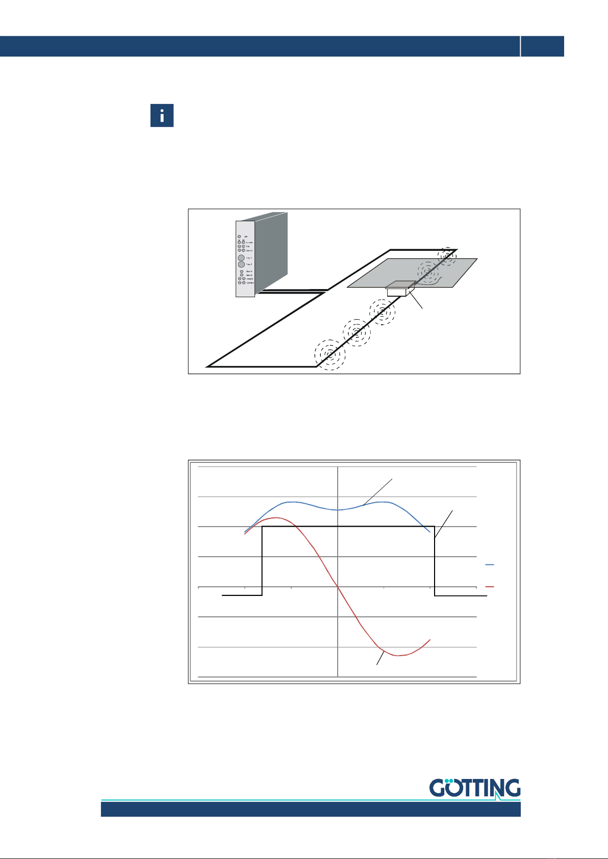
2.5 Functional Principle ............................................................................................................. 9
3 Mounting ......................................................................................... 11
3.1 Guide Wire ............................................................................................................................11
3.2 Energy Track.........................................................................................................................11
3.3 Inductive Guidance Sensor .............................................................................................. 11
3.3.1 Requirements ..................................................................................................................11
3.3.2 Mounting on the Vehicle ..............................................................................................11
3.3.3 Connection Cables (assembled on one side) / Terminating Resistors...........12
4 Commissioning ............................................................................... 14
5 Hardware ......................................................................................... 15
5.1 HG G-19370ZB/HG G-19380ZB (CAN Bus).................................................................15
5.1.1 LEDs....................................................................................................................................15
5.1.2 Pin Assignment ...............................................................................................................15
5.1.2.1 ST 1 ................................................................................................................................16
5.1.2.2 ST 2 / ST 3 (CAN 1 / CAN 2) ................................................................................... 16
5.2 HG G-19370YB/HG G-19380YB (Profinet) .................................................................. 17
5.2.1 LEDs....................................................................................................................................17
5.2.2 Pin Assignment ...............................................................................................................17
5.2.2.1 ST 1 ................................................................................................................................18
5.2.2.2 ST 2 / ST 3 (BUS 1 / BUS 2).................................................................................... 18
6 Configuration .................................................................................. 19
6.1 Turn-On Characteristic......................................................................................................19
6.2 Connection to a PC via the USB Interface ..................................................................19
6.3 Terminal Program ...............................................................................................................19
6.4 Service Program..................................................................................................................20
6.4.1 Main Menu........................................................................................................................20
6.4.1.1 HG G-19370/80ZB (CAN)......................................................................................... 20
6.4.1.2 HG G-19370/80YB (Profinet) ..................................................................................20
6.4.2 (1) Frequency Config .....................................................................................................21
6.4.3 (2) Calibration Config ....................................................................................................21
6.4.4 (3) Encoder Config .........................................................................................................22
6.4.5 (4) CSV ...............................................................................................................................23
6.4.6 HG G-19370ZB/HG G-19380ZB: (5) CAN Config .................................................. 24
6.4.7 Firmware Update ............................................................................................................24
7 CAN Bus Communication (HG G-19370ZB/HG G-19380ZB) ........ 26
7.1 Telegrams..............................................................................................................................26
7.2 Control and Status Telegrams ........................................................................................27
7.2.1 Incoming Telegram (IN) ................................................................................................ 27
7.2.2 Outgoing Telegram OUT1 ............................................................................................28

Device Description HG G-19370-B/HG G-19380-B | English, Revision 03 | Date: 05.05.2020
4Table of Contents
8 Profinet Communication (HG G-19370YB/HG G-19380YB)..........29
8.1 Input Bytes ............................................................................................................................29
8.2 Status/Detect (Byte 24) .....................................................................................................30
9 Maintenance ....................................................................................31
10 Technical Data.................................................................................32
11 List of Figures..................................................................................33
12 List of Tables ...................................................................................34
13 Index ................................................................................................35
14 Copyright and Terms of Liability....................................................37
14.1 Copyright ...............................................................................................................................37
14.2 Exclusion of Liability ..........................................................................................................37
14.3 Trade Marks and Company Names ...............................................................................37

Device Description HG G-19370-B/HG G-19380-B | English, Revision 03 | Date: 05.05.2020
5
About this Document – Chapter 1
1About this Document
1.1 Function
This device description contains information regarding the correct mounting, elec-
tric installation, commissioning and maintenance of the inductive guidance sensor
HG G-19370-B/HG G-19380-B for the technical personnel of a manufacturer who
wants to integrate the sensor into an automated guided vehicle (AGV).
This device description does not contain information regarding the usage of the su-
perordinate system, e.g. the automated guided vehicle (AGV). For this information
consult the documentation of the vehicle manufacturer resp. the operator of a facil-
ity.
This device description applies to devices with firmware version 1.01 and higher
(see Figure 10 on page 20).
1.2 Presentation of Information
For you to be able to use your product simply and safely this device description uses
consistent warning notices, symbols, terms and abbreviations. Those are described
in the following sections.
1.2.1 Warning Notices
In this device description warning notices appear before sequences of actions that
may lead to damage to persons or property. The listed actions for the danger preven-
tion have to be observed.
Warning notices have the following structure:
The warning symbol (warning triangle) indicates danger to life or risk of injury.
The signal word indicates the severity of the danger.
The paragraph kind or source of the danger names the kind or source of the
danger.
The paragraph consequences describes the consequences of not observing
the warning notice.
The paragraphs for danger prevention explain, how to avoid the danger.
SIGNAL WORD
Kind or source of the danger
Consequences
Danger prevention

Device Description HG G-19370-B/HG G-19380-B | English, Revision 03 | Date: 05.05.2020
6Chapter 1 – About this Document
The signal words have the following meanings:
1.2.2 Symbols
In this device description the following symbols and formatting are used:
If this information is ignored,
the product may not be operated in an optimal way.
Indicates one or more links to the Internet.
–www.goetting.de/xxx
–www.goetting.de/yyy
Indicates tips for easier
operation of the product.
The check mark lists a requirement.
The arrow shows an action step.
The indentation shows the result of an action or an action sequence.
Program texts and variables are indicated through the use of a fixed width
font.
Menu items and parameters are shown in cursive characters.
Whenever the pressing of letter keys is required for program entries, the
required etter eys are indicated as such (for any programs of Götting KG
small and capital letters are equally working).
Table 1 Hazard classification according to ANSI Z535.6-2006
Warning Symbol, Signal Word Meaning
DANGER
DANGER indicates a hazardous situation
which, if not avoided, will result in death or
serious injury.
WARNING
WARNING indicates a hazardous situation
which, if not avoided, could result in death or
serious injury.
CAUTION
CAUTION indicates a hazardous situation
which, if not avoided, could result in minor or
moderate injury.
NOTICE
NOTICE indicates property damage: The
product or the environment could be dam-
aged.

Device Description HG G-19370-B/HG G-19380-B | English, Revision 03 | Date: 05.05.2020
7
Introduction – Chapter 2
2Introduction
The inductive guidance sensor HG G-19370-B/HG G-19380-B is used for the induc-
tive track guidance of Automated Guided Vehicles (AGV). Up to 5 different guide wire
frequencies may be detected and evaluated simultaneously. If there is an existing
ground installation for the contact-less inductive energy transmission with two wires
(from here on also energy track) this can also be used for the track guidance. Within
the zone of influence of an active energy track guide wire signals can not be used.
The guide wire frequencies to be detected are configured via the USB interface. The
energy track depends on the variant of the inductive guidance sensor and is support-
ed in the implementations listed in Table 2 below. Additionally an incremental en-
coder for the measurement of distance or speed may be connected directly to the
sensor. All incremental encoders can be used that have a switching threshold > 10
V between high level and low level (typically 24V incremental encoders). The encod-
er values are also output via the bus.
2.1 Variants/Versions
The inductive guidance sensor is available in two different variants with different
bus / interface types. The variant is printed on the device‘s identification label.
2.2 Range of Use
The inductive guidance sensor is intended for indoor usage.
Inside the track a guide wire is layed that is operated in the frequency range 2 to
20 kHz. If there is an existing ground installation for the contact-less inductive
energy transmission this can also be used for the track guidance. These energy
tracks are supported in the implementations listed in Table 2 above. A matching
variant of the inductive guidance sensor has to be used. Within the zone of
influence of an active energy track guide wire signals can not be used.
The inductive guidance sensor can follow turn-offs in guide wire installations by
using different frequencies for the different wires.
The inductive guidance sensor can not follow turn-offs in energy track installa-
tions. Thus the energy track may not have switch points. For energy track instal-
lations with switch points Götting has different antennas with more than one
detection system.
The inductive guidance sensor is installed so that its underside faces the road-
way and meets the nominal reading distance towards the guide wire.
Table 2 Variant Overview
Variant Interface Energy Track
HG G-19370 ZB CAN Bus 25 kHz, 140 mm wire spacing, 85 A
YB Profinet
HG G-19380 ZB CAN Bus 140 kHz, 110 mm wire spacing, 45 A
YB Profinet

Device Description HG G-19370-B/HG G-19380-B | English, Revision 03 | Date: 05.05.2020
8Chapter 2 – Introduction
2.3 Qualification of the Users
The personnel intended to operate the inductive guidance sensor
has been provided with this documentation.
is familiar with the functionality of the inductive guidance sensor.
is trained sufficiently in mounting and configuring the inductive guidance sen-
sor and qualified to perform those tasks.
knows the risks posed by driverless vehicles and is trained in the necessary
safety precautions to assess the safe operational state of the system.
All personnel in the area of influence of the inductive guidance sensor is instructed
regarding the kind of the vehicle and the risks resulting from the driverless operation.
2.4 Intended Use
The inductive guidance sensor HG G-19370-B/HG G-19380-B is intended for the
track guidance of automated guided vehicles (AGV) along guide wires or ground in-
stallations for the contact-less inductive energy transmission (energy track). The
sensor detects the magnetic field above a guide wire or energy track with active cur-
rent flowing through it and continually calculates the actual deviation from the cen-
ter of the track. This deviation information is output via the bus.
In case the inductive guidance sensor is used for other purposes than specified
above or is modified all warranties against the Götting KG are null and void.
The sensor is only used according to section 2.2 on page 7. The sensor is only
mounted, configured, commissioned, operated, maintained and dismounted by per-
sonnel according to section 2.3 on page 8.
DANGER
Missing protection equipment
The inductive guidance sensor does not contain functionality to detect obstacles
or persons in front of a vehicle.
The vehicle manufacturer resp. operator has to include suitable safety
equipment.
DANGER
The vehicle leaving the track
Interferences as specified in section 3.3.1 on page 11 may lead to inaccurate
outputs whereby the vehicle may leave the track.
The vehicle manufacturer resp. operator has to include functionality to detect
this and stop the vehicle if needed
As an aid the Detect signal may be used (see below)

Device Description HG G-19370-B/HG G-19380-B | English, Revision 03 | Date: 05.05.2020
9
Introduction – Chapter 2
2.5 Functional Principle
The functional principle below is explained using a guide wire installation. An energy
track installation has slightly different voltage curves but the basic principle is the
same.
A frequency generator feeds a current into a guide wire installed in the ground.
Along this wire an alternating magnetic field is generated. The sensor measures the
magnitude of the induced voltage in two horizontal coils.
Figure 1 Principle of the guide wire track guidance
By evaluating the voltages induced in the two horizontal coils for each frequency a
sum and difference signal are calculated – Usum and Udiff – and output via the bus.
The difference signal shows maxima at both sides of the wire (one positive and one
negative) and crosses zero directly above the wire. Thus it may be used to control
the vehicle.
Figure 2 Voltage curves guide wire track guidance: Sum / difference signal and Detect
Frequency
Generator Vehicle
Inductive Guidance Sensor
Guide Wire
Magnetic Field
Frame
‐300
‐200
‐100
0
100
200
300
400
‐150 ‐10 0 ‐50 0 50 100 150
U
sum
U
diff
Detect 0/1
(output via bus)
Usum, signal strength decides
when to set Detect to 1
Udiff, vehicle control

Device Description HG G-19370-B/HG G-19380-B | English, Revision 03 | Date: 05.05.2020
10 Chapter 2 – Introduction
Due to the two coils the sum voltage may show two maxima. This depends on the
distance to the guide wire. The sum voltage is solely used to detect a guide wire (De-
tect signal). For this a detector circuit is implemented. The detector sets the Detect
signal to 1 for valid frequencies if the sum voltage exceeds a defined threshold.
Vehicle manufacturers may use the Detect signal as an aid to detect whether the ve-
hicle leaves the track.

Device Description HG G-19370-B/HG G-19380-B | English, Revision 03 | Date: 05.05.2020
11
Mounting – Chapter 3
3Mounting
3.1 Guide Wire
The guidelines for the ground installation of guide wires are explained in a separate
document. You can download the PDF file from the following address (section Ap-
plication Examples and Downloads):
http://www.goetting-agv.com/components/inductive/introduction
3.2 Energy Track
An existing ground installation for the contact-less inductive energy transmission is
used. The inductive guidance sensor is available in different variants for common
energy track installations, s. Table 2 on page 7.
3.3 Inductive Guidance Sensor
3.3.1 Requirements
Additional magnetic fields close to the sensor can affect the system characteristics.
Therefore:
The limit value for the magnetic field of e.g. transverters/engines/wire connec-
tions at the position of the inductive guidance sensor is circa 0,01 A/m.
3.3.2 Mounting on the Vehicle
Figure 3 Casing dimensions and mounting drill holes (all variants)
156,5
140
69,7
S2TST1 ST3
M12 circular connector BUS 1
Direction of travel
M12 circular connector BUS 2
Mounting Drill Holes ø 5,3 mm
depending on the bus type
M12x1 circular connector
8in-p (male)
A-coded
13
20
16
31
26,5
Lower edge of the device

Device Description HG G-19370-B/HG G-19380-B | English, Revision 03 | Date: 05.05.2020
12 Chapter 3 – Mounting
The inductive guidance sensor has two mounting drill holes with a diameter of 5.3
mm each with which it can be mounted by putting screws through the holes. The
drill holes have a distance of 140 mm to each other (center of hole <—> center of
hole). The inductive guidance sensor is to be mounted diagonally to the direction of
travel with the connectors facing upwards (first sketch in Figure 3 above). The rec-
ommended reading height is 40 to 200 mm from the bottom edge of the casing to
the guide wire. Nominal reading height is 60 mm.
Figure 4 Possible mounting position for the inductive guidance sensor
3.3.3 Connection Cables (assembled on one side) / Terminating Resistors
Continue by connecting the sensor to the vehicle control. For this you can use the
connectors ST 1, ST 2 and ST 3. The pin assignment is shown in section 5.1.2 on
page 15 so that you can make matching cables yourself that fit onto the standard M
12 connectors.
Alternatively the following connection cables can be ordered from Götting that are
pre-assembled on one side, the sensor side. The other side is a cable tail. ST 1 is the
same for all versions of the sensor. If you use the CAN bus version HG G-19370ZB/
HG G-19380ZB you can also order cables/terminators for ST 2 and ST 3. For the
Profinet version HG G-19370ZB/HG G-19380ZB there are no pre-configured cables
for ST 2 and ST 3 available.
NOTICE
Interferences of the CAN bus communication
Unshielded cables do not offer sufficient interference resistance.
For CAN shielded cables have to be used.
Direction of travel
Guide wire
Vehicle
Top
Road surface
Mounting the
sensor backside
to the vehicle
Reading height
above guide wire

Device Description HG G-19370-B/HG G-19380-B | English, Revision 03 | Date: 05.05.2020
13
Mounting – Chapter 3
Table 3 Accessories / connection cables / terminators
Possible Connection Cables
Connector Version Order No. Description
ST 1
19370/80ZB
HW CAB00008
Connection cable, PUR, 5 m, one-
sided M12 8 pin socket, A coded,
straight
19370/80YB
ST 2 19370/80ZB HW CON00055
or self-tailored
–CAN bus jack M12 with terminat-
ing resistor, 5 pin, A coded, if the
sensor is the last device on the
CAN bus
–Alternatively the CAN bus may be
connected through to further
devices with a self-made cable
19370/80YB self-tailored Profinet
ST 3 19370/80ZB HW CAB00064
Connection cable CAN bus, 10 m, 5-
pol., with shielding, one-sided M12
socket straight, A coded
19370/80YB self-tailored Profinet

Device Description HG G-19370-B/HG G-19380-B | English, Revision 03 | Date: 05.05.2020
14 Chapter 4 – Commissioning
4Commissioning
The inductive guidance sensor is pre-configured for a reading height of 60 mm and
the frequencies ordered by the customer. Thus it can theoretically be used without
an explicit commissioning.
The configuration has to be changed if the CAN bus version HG G-19370ZB/HG G-
19380ZB is used or an incremental encoder is to be connected. The Profinet inter-
face of version HG G-19370YB/HG G-19380YB does not have to be configured.
The CAN parameters have to be changed if — as is done in many applications — two
guidance sensors are mounted to one vehicle. Then the sensors need different Node
IDs. Thus at least one of the sensors has to have a different Node ID assigned.
For the commissioning configuration the USB interface is used. Connect it to your
PC as described in section 6.2 on page 19. Start a compatible terminal program on
the PC and open the guidance sensor‘s service program in it (section 6.4 on page
20). With the service program you can e.g. alter the following settings.
Depending on the application and the version the following settings may need to be
changed:
1. The six frequencies (they are pre-set according to what the customer ordered)
2. The gain and the thresholds (the sensor is pre-configured to a reading height of
60 mm, for the adaption to higher reading distances these can be changed)
3. CAN-BUS Node ID (if two inductive guidance sensors are used on the same
vehicle they need to have different Node IDs, so at least one of them need to be
re-configured)
4. CAN-BUS Baudrate (for adapting the CAN bus speed used in the vehicle)
5. Incremental encoder mode (if an incremental encoder is to be connected)

Device Description HG G-19370-B/HG G-19380-B | English, Revision 03 | Date: 05.05.2020
15
Hardware – Chapter 5
5Hardware
5.1 HG G-19370ZB/HG G-19380ZB (CAN Bus)
5.1.1 LEDs
Five LEDs allow a function check.
Figure 5 HG G-19370/80ZB (CAN): Position of the LEDs
5.1.2 Pin Assignment
The inductive guidance sensor has three connectors. The 8 pin plug ST 1 combines
the USB interface and allows to connect an incremental encoder. The USB connec-
tion to a PC can be used to configure the sensor (see section 6.4 on page 20). The 5
pin connectors CAN 1 and CAN 2 are used for the CAN bus communication. The
power supply is alternatively possible via ST 1 (USB 5V configuration only to Ub 24V)
or the CAN bus plugs (Ub 24V). Matching connection cables are listed in section
3.3.3 on page 12.
Table 4 HG G-19370/80ZB (CAN): Function of the LEDs
LED Function
PWR lit when operating voltage is connected
TD Track Detect, lit when a track is detected (sum voltage higher than
configured threshold)
ERR lit for CAN bus errors
CAN –blinking periodically when the sensor is ready for CAN bus com-
munication
–lit permanently during active CAN bus communiction
USB lit when a PC is connected (see section 6.2 on page 19)
NOTICE
Interferences of the CAN bus communication
Unshielded cables do not offer sufficient interference resistance.
For CAN shielded cables have to be used.

Device Description HG G-19370-B/HG G-19380-B | English, Revision 03 | Date: 05.05.2020
16 Chapter 5 – Hardware
Figure 6 HG G-19370/80ZB (CAN): Position of the connectors
5.1.2.1 ST 1
8 pin M 12 panel plug (A coded)
5.1.2.2 ST 2 / ST 3 (CAN 1 / CAN 2)
5 pin M 12 panel plugs (female / male)
For information about the CAN bus communication see chapter 7 on page 26.
Typically the inductive guidance sensor is the last device in the device chain on the
CAN bus. In this case a CAN terminating resistor (terminator) has to be plugged into
one of the CAN connectors (see section 3.3.3 on page 12).
Table 5 HG G-19370/80ZB (CAN): Pin assignment ST 1 8 pin
ST 1, male, A-codiert Pin Signal
1 VBUS (5V- via USB from the PC) up to Ub (24V)
2 GND
Incremental encoder
signals
3 Track A
4 Track B
5 Index Z
6 D+ (USB)
7 D- (USB)
8 GND
Table 6 HG G-19370/80ZB (CAN): Pin assignment ST 2 (CAN 1) and ST 3 (CAN 2), 5 pin
ST 2, CAN 1, female,
A coded
ST 3, CAN 2, male,
A coded Pin Signal
1 —
2 +Ub (24V)
3 GND
4 CAN_H
5 CAN_L
ST1 ST 2 / CAN 1 ST 3 / CAN 2
M12 x 1 circular connector
8 pin (male, A coded)
M12 x 1 circular connector
5 pin (female, A coded)
M12 x 1 circular connector
5 pin (male, A coded)

Device Description HG G-19370-B/HG G-19380-B | English, Revision 03 | Date: 05.05.2020
17
Hardware – Chapter 5
5.2 HG G-19370YB/HG G-19380YB (Profinet)
5.2.1 LEDs
Five LEDs allow a function check.
Figure 7 HG G-19370/80YB (Profinet): Position of the LEDs
5.2.2 Pin Assignment
The inductive guidance sensor has three connectors. The 8 pin plug ST 1 combines
the USB interface and allows to connect an incremental encoder. The USB connec-
tion to a PC can be used to configure the sensor (see section 6.4 on page 20). The 4
pin connectors ST 2 and ST 3 are used for the Profinet communication. The power
supply is realized via ST 1 (USB 5V configuration only up to Ub 24V).
Table 7 HG G-19370/80YB (Profinet): Function of the LEDs
LED Function
PWR lit when operating voltage is connected
ERR lit for errors (overmodulation of the amplifiers)
TD Track Detect, lit when a guide wire is detected (sum voltage higher
than configured threshold)
PTD lit when an energy track is detected
USB lit when a PC is connected (see section 6.2 on page 19)
– –
– –
PN SF lit for Profibus errors
PN RDY –lit when Profinet is ready
–blinking periodically when waiting for Profinet synchronization
PN BF –blinking periodically if a Profinet connection exists but there is
no communication with the Profinet controller
–lit when there is no Profinet connection available

Device Description HG G-19370-B/HG G-19380-B | English, Revision 03 | Date: 05.05.2020
18 Chapter 5 – Hardware
Figure 8 HG G-19370/80YB (Profinet): Position of the connectors
5.2.2.1 ST 1
8 pin M 12 panel plug (A coded)
5.2.2.2 ST 2 / ST 3 (BUS 1 / BUS 2)
5 pin M 12 panel plugs (female / male)
For information about the Profinet communication see chapter 8 on page 29.
Table 8 HG G-19370/80YB (Profinet): Pin assignment ST 1 8 pin
ST 1, male, A coded Pin Signal
1 VBUS (USB, 5V- via USB from the PC) up to Ub
(24V)
2 GND
Incremental encoder
signals
3 Track A
4 Track B
5 Index Z
6 D+ (USB)
7 D- (USB)
8 GND
Table 9 HG G-19370/80YB (Profinet): Pin assignment ST 2 & ST 3 (Profinet, female) 4 pin
ST 2 & ST 3, female, D coded Pin Signal
1 TX+
2 RX+
3 TX-
4 RX-
ST 1 ST 2 / BUS 1 ST 3 / BUS 2
M12 x 1 circular connector
8 pin (male, A coded)
M12 x 1 circular connector
4 pin (female, D coded)
M12 x 1 circular connector
4 pin (female, D coded)
1
2
3
4

Device Description HG G-19370-B/HG G-19380-B | English, Revision 03 | Date: 05.05.2020
19
Configuration – Chapter 6
6Configuration
6.1 Turn-On Characteristic
The device is functional directly after switching it on (by connecting the operating
voltage). It is ready to receive and send bus messages or to be configured via the
USB interface.
6.2 Connection to a PC via the USB Interface
The inductive guidance sensor is equipped with a USB interface for the diagnosis,
configuration and the update of its internal firmware. The USB interface is available
via the 8 pin connector St 1. A connection cable is listed in section 3.3.3 on page 12.
You have to attach a USB adapter/plug yourself to the following pins.
Figure 9 Connection example: Connection to the USB interface of a PC
The PC with Microsoft® Windows® needs to have the STM32 Virtual COM Port Driv-
er (STSW-STM32102) installed. This driver offers a virtual COM port. This COM port
(serial interface) can be used to establish a connection with a terminal program (see
below). If the STM32 Virtual COM Port Driver is not available via Plug & Play you can
download a setup program for the driver from the following address:
http://www.st.com/en/development-tools/stsw-stm32102.html
6.3 Terminal Program
Every terminal program compatible with the ANSI emulation can be used, examples
are HyperTerminal® or Tera Term®. HyperTerminal has been included in earlier ver-
sions of Microsoft® Windows®. Additionally it can be downloaded from the follow-
ing address:
https://www.hilgraeve.com/hyperterminal/
Start the terminal program on the PC. The COM port has to be set to the port con-
figured by the virtual port driver.
USB adaptor/plug
(to be tailored
by the customer)
All other pins:
Do not connect
ST 1
Guidance Sensor
Computer (e.g. PC
or Laptop) with
USB interface
1
1
1
VBUS (5V-)VBUS (5V-)
Type A Type B D+
D+
D-
D-
GND
GND
2
2
2
3
33
4
44
1
2
3
4
5
6
7
8

Device Description HG G-19370-B/HG G-19380-B | English, Revision 03 | Date: 05.05.2020
20 Chapter 6 – Configuration
6.4 Service Program
When the connection inside the Terminal Program (see above) is successfully estab-
lished press any key to make the following main menu appear.
6.4.1 Main Menu
The main menu differs for the sensor versions. For version HG G-19370ZB/HG G-
19380ZB an additional CAN menu is available. The main menu always shows the
five guide wire frequencies and the frequency of the energy track as well as the cor-
responding actual sum and difference values.
6.4.1.1 HG G-19370/80ZB (CAN)
Figure 10 HG G-19370/80ZB (CAN): Main menu
6.4.1.2 HG G-19370/80YB (Profinet)
Figure 11 HG G-19370/80YB (Profinet): Main menu
Frequency config, s. section 6.4.2 on page 21
Calibration config, s. section 6.4.3 on page 21
Encoder config, s. section 6.4.4 on page 22
CSV, s. section 6.4.5 on page 23
CAN config, s. section 6.4.6 on page 24 (only visible for version HG G-
19370ZB/HG G-19380ZB)
Firmware Update, s. section 6.4.5 on page 23
HG 19370 ZB V1.01 Main menu Goetting KG
Frequencies: 5000 6000 7000 8000 10000 25000
Sum: 0 0 0 0 358 0
Dif: 0 0 0 0 0 0
Encoder: 0
1: Frequency config
2: Calibration config
3: Encoder config
4: Serial Data-Stream
5: CAN config
U: Firmware Update
HG 19370 YB V1.01 Main menu Goetting KG
Frequencies: 5000 6000 7000 8000 10000 25000
Sum: 0 0 0 0 358 0
Dif: 0 0 0 0 0 0
Encoder: 0
1: Frequency config
2: Calibration config
3: Encoder config
4: Serial Data-Stream
U: Firmware Update
This manual suits for next models
3
Table of contents
Other Gotting Accessories manuals
Popular Accessories manuals by other brands

Integrated Visual Data Technology Inc.
Integrated Visual Data Technology Inc. ED3 SkidWeigh Plus Series Installation & Calibration Manual

Zap
Zap ACC200 quick start guide

Intermec
Intermec CK61 instructions

KSB
KSB KSB Leakage Sensor Installation & operating manual

Mutsy
Mutsy Spider instruction manual

LI-COR
LI-COR LI-1500 installation guide