Gotting HG G-19370ZA User manual

Device Description HG G-19370ZA | English, Revision 01 | Date: 17.05.2017 | www.goetting-agv.com
2Overview HG G-19370ZA
Summary
Characteristics of the inductive guidance sensor HG G-19370ZA:
•6 programmierbare, gleichzeitig nutz-
bare Frequenzen
•Programmierbare Verstärkung
•Indoor
•Anschluss für Inkrementalgeber
•CAN-Bus Schnittstelle
•USB Schnittstelle
•Serielle Schnittstelle (über USB Virtual
Port Driver)
® 2017 Götting KG, errors and modifications reserved.
The Götting KG in D-31275 Lehrte has
a certified quality management system
according to ISO 9001.

Device Description HG G-19370ZA | English, Revision 01 | Date: 17.05.2017 | www.goetting-agv.com
3Table of Contents HG G-19370ZA
Contents
1 About this Document ............................................................................. 5
1.1 Function................................................................................................................................. 5
1.2 Symbols ................................................................................................................................. 5
2 Introduction............................................................................................. 7
2.1 Range of Use ........................................................................................................................ 7
2.2 Qualification of the Users................................................................................................. 7
2.3 Intended Use ........................................................................................................................ 8
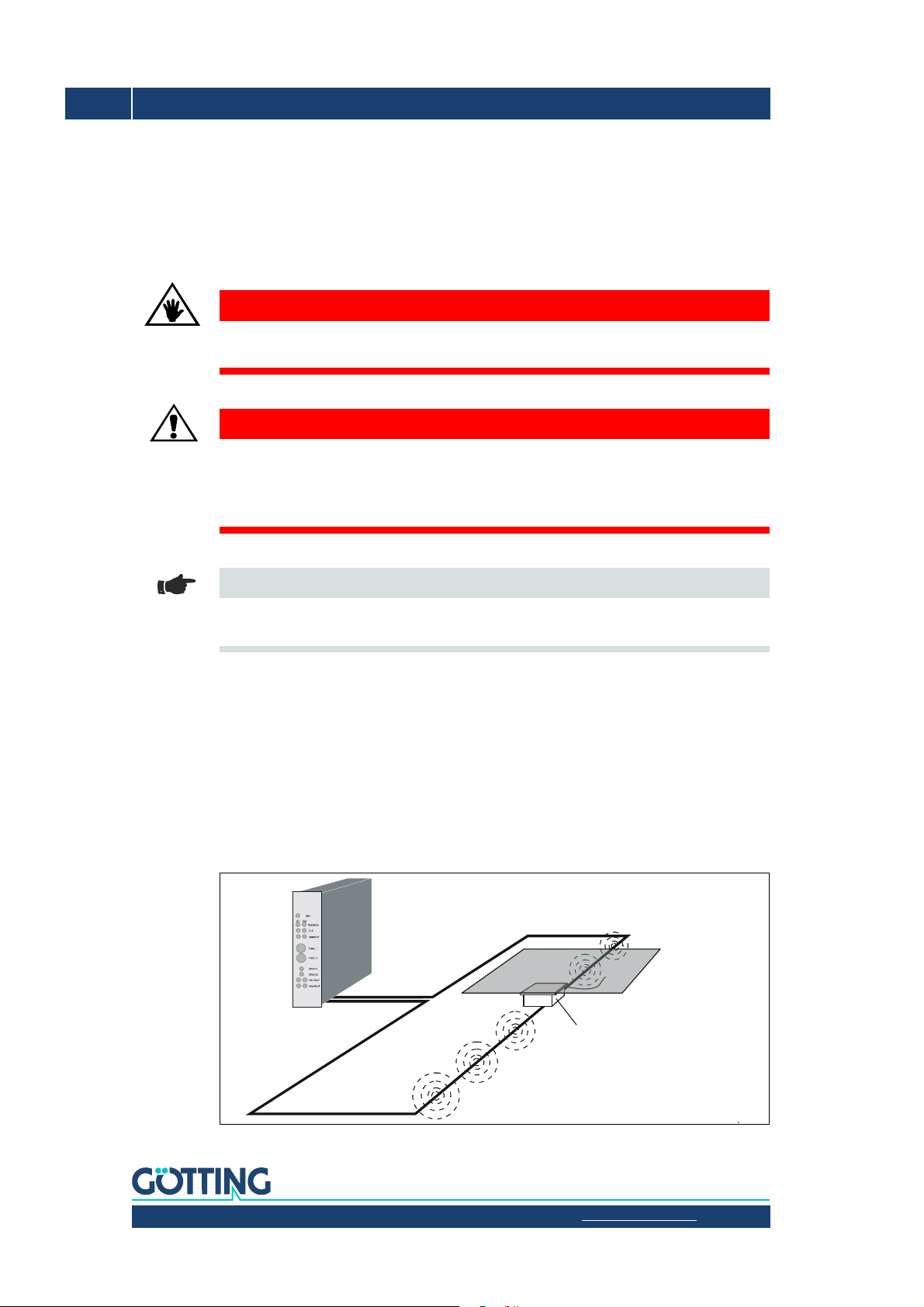
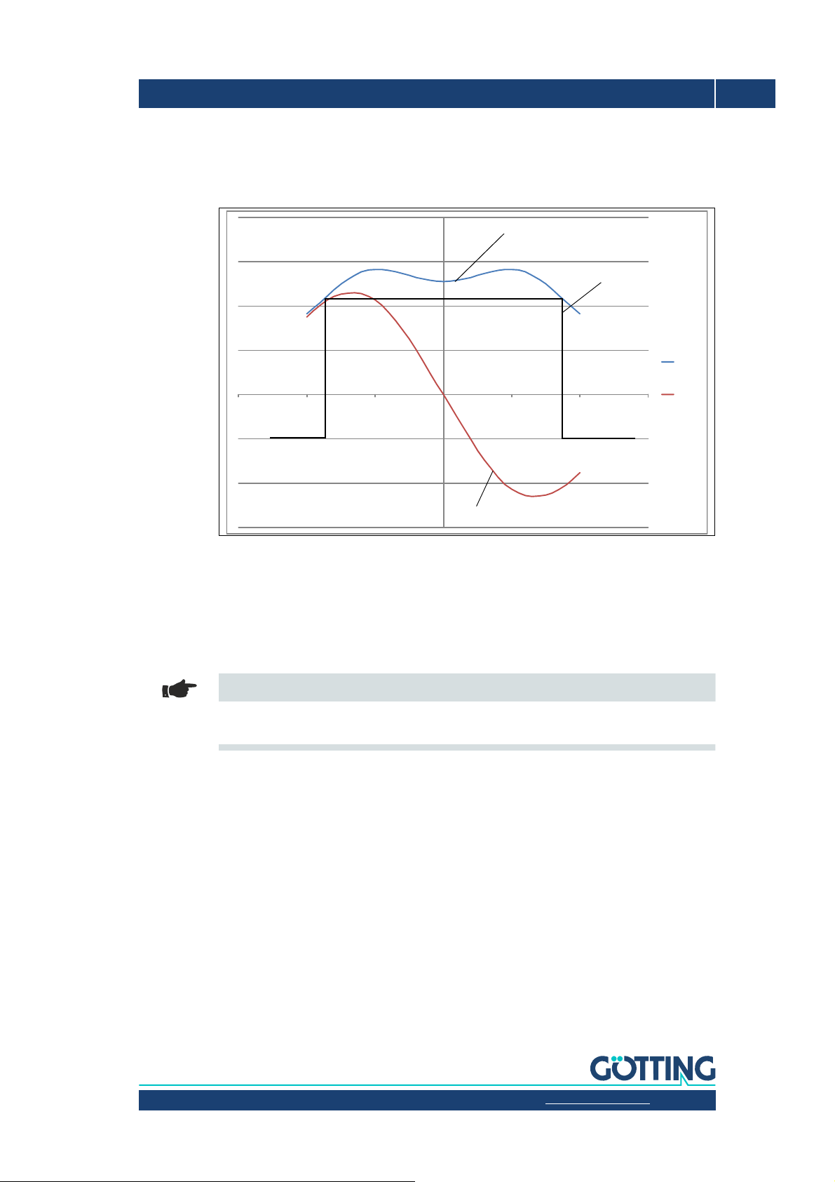
2.4 Functional Principle ........................................................................................................... 8
3 Mounting ............................................................................................... 10
3.1 Guide Wire ..........................................................................................................................10
3.2 Inductive Guidance Sensor ............................................................................................10
3.2.1 Requirements..................................................................................................................................10
3.2.2 Mounting on the Vehicle .............................................................................................................11
3.2.3 Connection Cables (assembled on one side) / CAN Terminating Resistor ..................12
4 Commissioning ..................................................................................... 13
5 CAN Bus Communication .................................................................... 14
5.1 Telegrams............................................................................................................................14
5.2 Control and Status Telegrams ......................................................................................15
5.2.1 Incoming Telegram (IN) ...............................................................................................................15
5.2.2 Outgoing Telegram OUT1 ...........................................................................................................15
6 Hardware ............................................................................................... 16
6.1 LEDs ......................................................................................................................................16
6.2 Pin Assignment .................................................................................................................16
6.2.1 ST 1 ....................................................................................................................................................17
6.2.2 CAN 1 / CAN 2 ................................................................................................................................17
7 Configuration ........................................................................................ 18
7.1 Turn-On Characteristic....................................................................................................18
7.2 Connection to a PC via the USB Interface ................................................................18
7.3 Terminal Program .............................................................................................................18
7.4 Service Program................................................................................................................19
7.4.1 (1) Frequency Config ....................................................................................................................20
7.4.2 (2) CAN Config................................................................................................................................20
7.4.3 (3) Calibration Config ...................................................................................................................21
7.4.4 (4) Encoder Config ........................................................................................................................22
7.4.5 (6) Serial Data-Stream..................................................................................................................22
7.4.6 Firmware Update ...........................................................................................................................23
8 Maintenance.......................................................................................... 24

Device Description HG G-19370ZA | English, Revision 01 | Date: 17.05.2017 | www.goetting-agv.com
4Table of Contents HG G-19370ZA
9 Technical Data ...................................................................................... 25
10 List of Figures....................................................................................... 26
11 List of Tables ........................................................................................ 27
12 Copyright and Terms of Liability ........................................................ 28
12.1 Copyright ............................................................................................................................ 28
12.2 Exclusion of Liability ....................................................................................................... 28
12.3 Trade Marks and Company Names............................................................................. 28

Device Description HG G-19370ZA | English, Revision 01 | Date: 17.05.2017 | www.goetting-agv.com
5Chapter 1: About this Document HG G-19370ZA
1About this Document
1.1 Function
This device description contains information regarding the correct mounting, electric instal-
lation, commissioning and maintenance of the inductive guidance sensor HG G-19370ZA
for the technical personnel of a manufacturer who wants to integrate the sensor into an au-
tomated guided vehicle (AGV).
This device description does not contain information regarding the usage of the superordi-
nate system, e.g. the automated guided vehicle (AGV). For this information consult the doc-
umentation of the vehicle manufacturer resp. the operator of a facility.
This device description applies to devices with firmware version 1.10 and higher (see Figure
8 on page 19).
1.2 Symbols
The following symbols and formatting are used in Götting documentations:
Note
Indicates technical information that should be followed when using the device.
ATTENTION!
Indicates dangers that may lead to damages or the destruction of the device.
BEWARE!
Indicates dangers that may lead to injuries or severe damage of property.
WARNING!
Indicates dangers that may lead to injuries, potentially with loss of life, or severe damage of
property.
Tip
Indicates information that makes handling of the device easier.

Device Description HG G-19370ZA | English, Revision 01 | Date: 17.05.2017 | www.goetting-agv.com
6Chapter 1: About this Document HG G-19370ZA
Link
Indicates additional information in the internet, e.g. on our homepage www.goetting-
agv.com. Those links are clickable in the PDF version of this documentation.
Program texts and variables are indicated through the use of a fixed width
font.
Whenever the pressing of letter keys is required for program entries, the required
etter eys are indicated as such (for any programs of Götting KG small and capital
letters are equally valid).

Device Description HG G-19370ZA | English, Revision 01 | Date: 17.05.2017 | www.goetting-agv.com
7Chapter 2: Introduction HG G-19370ZA
2Introduction
The inductive guidance sensor HG G-19370ZA is used for the inductive track guidance of
Automated Guided Vehicles (AGV). Up to 6 different guide wire frequencies may be detect-
ed and evaluated simultaneously. The frequencies may be chosen from the range 2 to
20 kHz and are configured via the USB interface. Additionally am incremental encoder for
the measurement of distance or speed may be connected directly to the sensor. All incre-
mental encoders can be used that have a switching threshold > 10 V between high level
and low level (typically 24V incremental encoders). The encoder values are also output via
the CAN bus.
2.1 Range of Use
•The inductive guidance sensor is intended for indoor usage.
•Inside the track a guide wire is layed that is operated in the frequency range 2 to
20 kHz.
•The magnetic sensor is installed so that its underside faces the roadway and meets
the nominal reading distance towards the guide wire.
2.2 Qualification of the Users
The personnel intended to operate the magnetic sensor
•has been provided with this documentation.
•is familiar with the functionality of the inductive guidance sensor.
•is trained sufficiently in mounting and configuring the magnet sensor and qualified to
perform those tasks.
•knows the risks posed by driverless vehicles and is trained in the necessary safety
precautions to assess the safe operational state of the system.
All personnel in the area of influence of the magnetic sensor is instructed regarding the kind
of the vehicle and the risks resulting from the driverless operation.

Device Description HG G-19370ZA | English, Revision 01 | Date: 17.05.2017 | www.goetting-agv.com
8Chapter 2: Introduction HG G-19370ZA
2.3 Intended Use
The inductive guidance sensor HG G-19370ZA is intended for the track guidance of auto-
mated guided vehicles (AGV) along guide wires. The sensor uses two horizontal coils to de-
tect the magnetic field above a guide wire with active current flowing through it and thus
continually calculates the actual deviation from the center of the track. This deviation infor-
mation is output via the CAN bus.
WARNING!
The inductive guidance sensor does not contain functionality to detect obstacles or persons
in front of a vehicle! The vehicle manufacturer has to include suitable safety equipment.
BEWARE!
Interferences as specified in section 3.2.1 on page 10 may lead to inaccurate outputs
whereby the vehicle may leave the track. The vehicle manufacturer has to include function-
ality to detect this and stop the vehicle if needed. As an aid the Detect signal may be used
(see below).
Note
In case the inductive guidance sensor is used for other purposes than specified above or is
modified all warranties against the Götting KG are null and void.
The sensor is only used according to section 2.1 on page 7. The sensor is only mounted,
configured, commissioned, operated, maintained and dismounted by personnel according
to section 2.2 on page 7.
2.4 Functional Principle
A frequency generator feeds a current into a guide wire installed in the ground. Along this
wire an alternating magnetic field is generated. The sensor measures the magnitude of the
induced voltage in two horizontal coils.
Figure 1 Principle of the guide wire track guidance
Frequency
Generator Vehicle
Inductive Guidance Sensor
Guide Wire
Magnetic Field
Frame

Device Description HG G-19370ZA | English, Revision 01 | Date: 17.05.2017 | www.goetting-agv.com
9Chapter 2: Introduction HG G-19370ZA
By evaluating the voltages induced in the two horizontal coils for each frequency a sum and
difference signal are calculated – Usum and Udiff – and output via the CAN bus. The differ-
ence signal shows maxima at both sides of the wire (one positive and one negative) and
crosses zero directly above the wire. Thus it may be used to direct the vehicle.
Figure 2 Voltage curves sum and difference signal and Detect
Due to the two coils the sum voltage may show to maxima. This depends on the distance
to the guide wire. The sum voltage is solely used to detect a guide wire (Detect signal). For
this a detector circuit is implemented. The detector sets the Detect signal to 1 for valid fre-
quencies if the sum voltage exceeds a defined threshold. The Detect signal for all frequen-
cies is output via the CAN bus.
Note
Vehicle manufacturers may use the Detect signal as an aid to detect whether the verhicle
leaves the track.
‐300
‐200
‐100
0
100
200
300
400
‐150 ‐100 ‐50 0 50 100 150
U
sum
U
diff
Detect 0/1
(output via CAN)
Usum, signal strength decides
when to set Detect to 1
Udiff, vehicle control

Device Description HG G-19370ZA | English, Revision 01 | Date: 17.05.2017 | www.goetting-agv.com
10 Chapter 3: Mounting HG G-19370ZA
3Mounting
3.1 Guide Wire
The guidelines for the ground installation of guide wires are explained in a separate docu-
ment. You can download the PDF file from the following address (section Application Ex-
amples and Downloads):
Link
http://www.goetting-agv.com/components/inductive/introduction
3.2 Inductive Guidance Sensor
3.2.1 Requirements
Note
Additional magnetic fields close to the sensor can affect the system characteristics. There-
fore:
– The limit value for the magnetic field of e.g. transverters/engines/wire connections at
the position of the inductive guidance sensor is circa 0,01 A/m.

Device Description HG G-19370ZA | English, Revision 01 | Date: 17.05.2017 | www.goetting-agv.com
11Chapter 3: Mounting HG G-19370ZA
3.2.2 Mounting on the Vehicle
Figure 3 Casing dimensions and mounting drill holes
The inductive guidance sensor has two drill holes with a diameter of 5.3 mm each with
which it can be mounted by putting screws through the holes. The drill holes have a dis-
tance of 140 mm to each other (center of hole <—> center of hole). The magnet sensor is
to be mounted diagonally to the direction of travel with the connectors facing upwards (first
sketch in Figure 3 above). The recommended reading height is 60 to 200 mm from the bot-
tom edge of the casing to the guide wire.
Figure 4 Possible mounting position for the inductive guidance sensor
Direction
of travel
Lower edge
of the device
ST1 CAN 1 CAN 2
M12 x 1 circular connector
8 pin (male, A coded)
M12 x 1 circular connector
5 pin (female, A coded)
M12 x 1 circular connector
5 pin (female, A coded)
Mounting drill holes
Direction of travel
Guide wire
Vehicle
Top
Road surface
Mounting the
sensor backside
to the vehicle
Reading height
above guide wire

Device Description HG G-19370ZA | English, Revision 01 | Date: 17.05.2017 | www.goetting-agv.com
12 Chapter 3: Mounting HG G-19370ZA
3.2.3 Connection Cables (assembled on one side) / CAN Terminating Resistor
Continue by connecting the sensor to the vehicle control. For this you can use the connec-
tors ST 1, CAN 1 and CAN 2. The pin assignment is shown in section 6.2 on page 16 so you
can make matching cables yourself that fit onto the standard M 12 connectors.
ATTENTION!
For CAN shielded cables have to be used!
Alternatively the following connection cables can be ordered from Götting that are pre-as-
sembled on one side, the sensor side. The other side is a cable tail. Typically the sensor is
the last device on the CAN bus, then CAN 1 receives a terminating resistor (CAN terminator).
This case is shown in the table below. Alternatively the CAN bus may be connected through
to further devices. In that case you have to make the connection cable for CAN 1 yourself.
Possible Connection Cable
Connector Order No. Description
ST 1 HW CAB00008 Connection cable, PUR, 5 m, one-sided M12 8 pin socket,
A coded, straight
CAN 1 HW CON00055 – CAN bus jack M12 with terminating resistor, 5 pin, A
coded, if the sensor is the last device on the CAN bus
– Alternatively the CAN bus may be connected through
to further devices
CAN 2 HW CAB00064 Connection cable CAN bus, 10 m, 5-pol., with shielding,
one-sided M12 socket straight, A coded
Table 1 Accessories / connection cables / CAN terminator

Device Description HG G-19370ZA | English, Revision 01 | Date: 17.05.2017 | www.goetting-agv.com
13Chapter 4: Commissioning HG G-19370ZA
4Commissioning
The inductive guidance sensor is pre-configured for a reading height of 60 mm and the fre-
quencies ordered by the customer. Thus it can theoretically be used without an explicit
commissioning. However in almost all applications at least the CAN bus Node ID and baud
rate are configured to match vehicle control.
Note
The CAN parameters have to be changed if — as is done in many applications — two guid-
ance sensors are mounted to one vehicle. Then the sensors need different Node IDs. Thus
at least one of the sensors has to have a different Node ID assigned.
For the commissioning configuration the USB interface is used. Connect it to your PC as de-
scribed in section 7.2 on page 18. Start a compatible terminal program on the PC and open
the guidance sensor‘s service program in it (section 7.4 on page 19). With the service pro-
gram you can e.g. alter the following settings.
Depending on the application the following settings may need to be changed:
1. The six frequencies (they are pre-set according to what the customer ordered)
2. The gain and the thresholds (the sensor is pre-configured to a reading height of
60 mm, for the adaption to higher reading distances these can be changed)
3. CAN-BUS Node ID (if two inductive guidance sensors are used on the same vehicle
they need to have different Node IDs, so at least one of them need to be re-config-
ured)
4. CAN-BUS Baudrate (for adapting the CAN bus speed used in the vehicle)
5. Incremental encoder mode (if an incremental encoder is to be connected)

Device Description HG G-19370ZA | English, Revision 01 | Date: 17.05.2017 | www.goetting-agv.com
14 Chapter 5: CAN Bus Communication HG G-19370ZA
5CAN Bus Communication
The CAN bus communication is coordinated by the vehicle control. The vehicle control
sends commands with specific CAN IDs and receives the reply telegrams of the addressed
devices on the bus. The inductive guidance sensor sends its status, the sum and difference
values for the 6 frequencies and the incremental encoder values.
5.1 Telegrams
The devices expect a telegram on CAN ID 0x200+ NodeID and reply accordingly on CAN-ID
0x180+ NodeID. With the control word (see below) the output of the sum and difference
signals can be de-/activated for each frequency (aka track).
Note
Bytes listed with a 0 as the last position of the description stand for LowByte. The byte with
the highest number for the same value is the HighByte.
– Control, Status, Enc and Speed are explained in the tables for IN and OUT1 below.
Enc is the counter reading for the incremental encoder as a 16 bit integer value
(going from 0 to 65,535, then it re-starts with 0). For speed every 10 ms the differ-
ence between the previous and the actual encoder counter reading is calculated.
– The telegrams OUT2 to OUT 4 have a uniform structure. They transmit the sum and
difference values in mV for two frequencies each. The sum voltage is an unsigned 16
bit integer value. The difference voltage is a signed 16 bit integer value. The values
are from the range as shown in Figure 2 on page 9.
IO CAN-ID Byte 0 Byte 1 Byte 2 Byte 3 Byte 4 Byte 5 Byte 6 Byte 7
IN 0x200 +
Node-ID
Control_0 Control_1
OUT1 0x180 +
Node-ID
Status_0 Status_1 Status_2 Status_3 Enc_0 Enc_1 Speed_0 Speed_1
OUT2 0x280 +
Node-ID
S1_Sum0 S1_Sum1 S1_Dif0 S1_Dif1 S2_Sum0 S2_Sum1 S2_Dif0 S2_Dif1
OUT3 0x380 +
Node-ID
S3_Sum0 S3_Sum1 S3_Dif0 S3_Dif1 S4_Sum0 S4_Sum1 S4_Dif0 S4_Dif1
OUT4 0x480 +
Node-ID
S5_Sum0 S5_Sum1 S5_Dif0 S5_Dif1 S6_Sum0 S6_Sum1 S6_Dif0 S6_Dif1
Table 2 CAN telegrams

Device Description HG G-19370ZA | English, Revision 01 | Date: 17.05.2017 | www.goetting-agv.com
15Chapter 5: CAN Bus Communication HG G-19370ZA
5.2 Control and Status Telegrams
5.2.1 Incoming Telegram (IN)
Meaning shown for bit = 1 each.
5.2.2 Outgoing Telegram OUT1
Control Bit Meaning
0Track 1 active
1Track 2 active
2Track 3 active
3Track 4 active
4Track 5 active
5Track 6 active
6Reverse driving ON
7 —
8Incremental encoder ON
9Invert direction of incremental encoder
10 - 15 —
Table 3 CAN IN telegram structure (control bits)
Bit Type Meaning
0
Status
Track 1 active
1Track 2 active
2Track 3 active
3Track 4 active
4Track 5 active
5Track 6 active
6Reverse driving ON
7 —
8Incremental encoder ON
9Invert direction of incremental encoder
10 - 15 —
16 Track 1 detected
17 Track 2 detected
18 Track 3 detected
19 Track 4 detected
20 Track 5 detected
21 Track 6 detected
24 - 31 Counter as sign of life, is incremented for each telegram
32 - 47 Enc Incremental encoder counter reading
48 - 63 Speed Difference between current incremental encoder counter reading and
the counter reading from 10 ms ago
Table 4 CAN OUT1 telegram structure (status, incremental encoder)

Device Description HG G-19370ZA | English, Revision 01 | Date: 17.05.2017 | www.goetting-agv.com
16 Chapter 6: Hardware HG G-19370ZA
6Hardware
6.1 LEDs
Five LEDs allow a function check.
Figure 5 Position of the LEDs
6.2 Pin Assignment
The inductive guidance sensor has three connectors. The 8 pin plug ST 1 combines the USB
interface and allows to connect an incremental encoder. The USB connection to a PC can
be used to configure the sensor (see section 7.4 on page 19). The 5 pin connectors CAN 1
and CAN 2 are used for the CAN bus communication. Matching connection cables are listed
in section 3.2.3 on page 12.
ATTENTION!
For CAN shielded cables have to be used!
LED Function
PWR lit when operating voltage is connected
TD Track Detect, lit when a track is detected (sum voltage higher than con-
figured threshold)
ERR lit for CAN bus errors
CAN – blinking periodically when the sensor is ready for CAN bus commu-
nication
– lit permanently during active CAN bus communiction
USB lit when a PC is connected (see section 7.2 on page 18)
Table 5 Function of the LEDs

Device Description HG G-19370ZA | English, Revision 01 | Date: 17.05.2017 | www.goetting-agv.com
17Chapter 6: Hardware HG G-19370ZA
Figure 6 Position of the connectors
6.2.1 ST 1
8 pin M 12 panel plug (A coded)
6.2.2 CAN 1 / CAN 2
5 pin M 12 panel plugs (female / male)
For information about the CAN bus communication see chapter 5 on page 14.
Note
Typically the inductive guidance sensor is the last device in the device chain on the CAN
bus. In this case a CAN terminating resistor (terminator) has to be plugged into one of the
CAN connectors (see section 3.2.3 on page 12).
ST 1 Pin Signal
1VBUS (USB, 5V- via USB from the PC)
2GND
Incremental encoder
signals
3Track A
4Track B
5Index Z
6D+ (USB)
7D- (USB)
8GND (USB)
Table 6 Pin assignment ST 1 8 pin
CAN 1 CAN 2 Pin Signal
1 —
2+Ub (24V)
3GND
4CAN_H
5CAN_L
Table 7 Pin assignment CAN 1 (female) and CAN 2 (male) 5 pin
ST1 CAN 1 CAN 2
M12 x 1 circular connector
8 pin (male, A coded)
M12 x 1 circular connector
5 pin (female, A coded)
M12 x 1 circular connector
5 pin (female, A coded)

Device Description HG G-19370ZA | English, Revision 01 | Date: 17.05.2017 | www.goetting-agv.com
18 Chapter 7: Configuration HG G-19370ZA
7Configuration
7.1 Turn-On Characteristic
The device is functional directly after switching it on (by connecting the operating voltage).
It is ready to receive and send CAN bus messages or to be configured via the USB interface.
7.2 Connection to a PC via the USB Interface
The inductive guidance sensor is equipped with a USB interface for the diagnosis, configu-
ration and the update of its internal firmware. The USB interface is available via the 8 pin
connector St 1. A connection cable is listed in section 3.2.3 on page 12. You have to attach
a USB adapter/plug yourself to the following pins.
Figure 7 Connection example: Connection to the USB interface of a PC
The PC with Microsoft® Windows® needs to have the STM32 Virtual COM Port Driver
(STSW-STM32102) installed. This driver offers a virtual COM port. This COM port (serial in-
terface) can be used to establish a connection with a terminal program (see below). If the
STM32 Virtual COM Port Driver is not available via Plug & Play you can download a setup
program for the driver from the following address:
Link
http://www.st.com/en/development-tools/stsw-stm32102.html
7.3 Terminal Program
Every terminal program compatible with the ANSI emulation can be used, examples are Hy-
perTerminal® or Tera Term®. HyperTerminal has been included in earlier versions of Micro-
soft® Windows®. Additionally it can be downloaded from the following address:
Link
https://www.hilgraeve.com/hyperterminal/
USB adaptor/plug
(to be tailored
by the customer)
All other pins:
Do not connect
ST 1
Guidance Sensor
Computer (e.g. PC
or Laptop) with
USB interface
1
1
1
VBUS (5V-)VBUS (5V-)
Type A Type B D+
D+
D-
D-
GND
GND
2
2
2
3
33
4
44
1
2
3
4
5
6
7
8

Device Description HG G-19370ZA | English, Revision 01 | Date: 17.05.2017 | www.goetting-agv.com
19Chapter 7: Configuration HG G-19370ZA
Start the terminal program on the PC. The COM port has to be set to the port configured by
the virtual port driver. When the connection is established successfully press any key to
make the main menu shown in 7.4 below appear in the terminal program.
7.4 Service Program
Figure 8 Main menu
•Frequency config, s. section 7.4.1 on page 20
•CAN config, s. section 7.4.2 on page 20
•Calibration config, s. section 7.4.3 on page 21
•Encoder config, s. section 7.4.4 on page 22
•Serial Data-Stream, s. section 7.4.5 on page 22
•Firmware Info, output of the firmware version currently running in the sensor
•Firmware Update, s. section 7.4.5 on page 22
•Reboot, triggers a re-start of the inductive guidance sensor
HG19370 Main menu Goetting KG
1: Frequency config
2: CAN config
3: Calibration config
4: Encoder config
5: Serial Data-Stream
I: Firmware Info
U: Firmware Update
R: Reboot
Press any other key to quit

Device Description HG G-19370ZA | English, Revision 01 | Date: 17.05.2017 | www.goetting-agv.com
20 Chapter 7: Configuration HG G-19370ZA
7.4.1 (1) Frequency Config
Definition of the six frequencies for which the sum and difference signals are calculated.
Figure 9 Menu Frequency Select
7.4.2 (2) CAN Config
Configuration of NodeID and Baudrate. The sub menu CAN-Status lists the reception and
transmission counters as well as possible errors. Additionally CAN statistics are shown (RX
packet counter, TX packet counter, error counter).
Figure 10 Menu CAN config
HG19370 Frequency Select Goetting KG
Active Frequencies: 1000;5710;6666;8000;8888;11430
1: Edit single Frequency
2: Edit all Frequencies
Press any other key to quit
HG19370 CAN config Goetting KG
NodeID: 1
Baudrate: 250 kBit/s
1: Edit Node ID
2: Edit Baudrate
3: CAN Status
Press any other key to quit
Table of contents
Other Gotting Accessories manuals
Popular Accessories manuals by other brands

Bresser
Bresser 91-32000 operating instructions

Peerless/Morel
Peerless/Morel 302-900 Assembly instructions

Sunjoy
Sunjoy 80QT Assembly and care instructions

Eaton
Eaton Crouse-Hinds IF 1744 Installation & maintenance information

Krüger & Matz
Krüger & Matz KM0910 owner's manual

PCB Piezotronics
PCB Piezotronics 208M216 Installation and operating manual