Gotting HG G-84300ZD User manual

Device Description HG G-84300ZD | English, Revision 10 | Date: 01.06.2022
2Overview
Summary
Characteristics of the Gyro HG G-84300ZD:
•Output: Angle, 0° – 360°,
resolution 0.01°
•Data rate of measurement output:
1 to 100 Hz
•Maximum spin rate: 300 °/s
•Compact, light weight IP65 casing
•Robust (no moving parts)
•Wide operating temperature range from
-40 to +85° C
•Long lifetime (MTBF > 100,000 h),
maintenance free
•Interfaces: CAN/CANopen® (data) &
USB (service / configuration)
© 2022 Götting KG, errors and modifications reserved.
The Götting KG in D-31275 Lehrte has
a certified quality management system
according to ISO 9001.

Device Description HG G-84300ZD | English, Revision 10 | Date: 01.06.2022
3
Table of Contents
1 About this Document....................................................................................5
1.1 Warning Notices..........................................................................................................................................5
1.2 Symbols...........................................................................................................................................................6
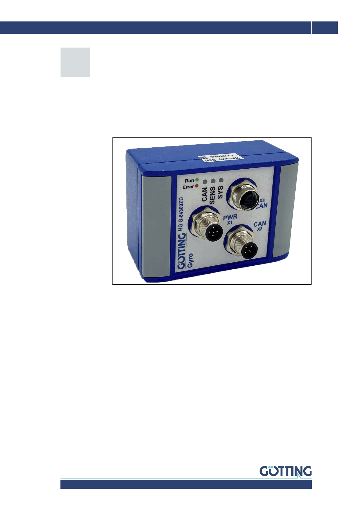
2 Introduction....................................................................................................7
3 Hardware ........................................................................................................8
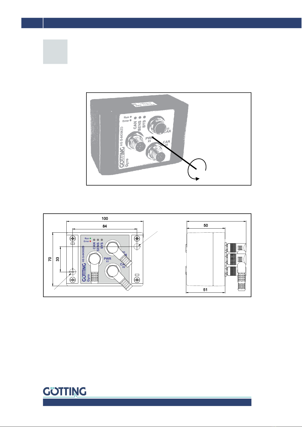
3.1 Alignment of the Measuring Axis........................................................................................................8
3.2 Dimensions....................................................................................................................................................8
3.3 Mounting ........................................................................................................................................................8
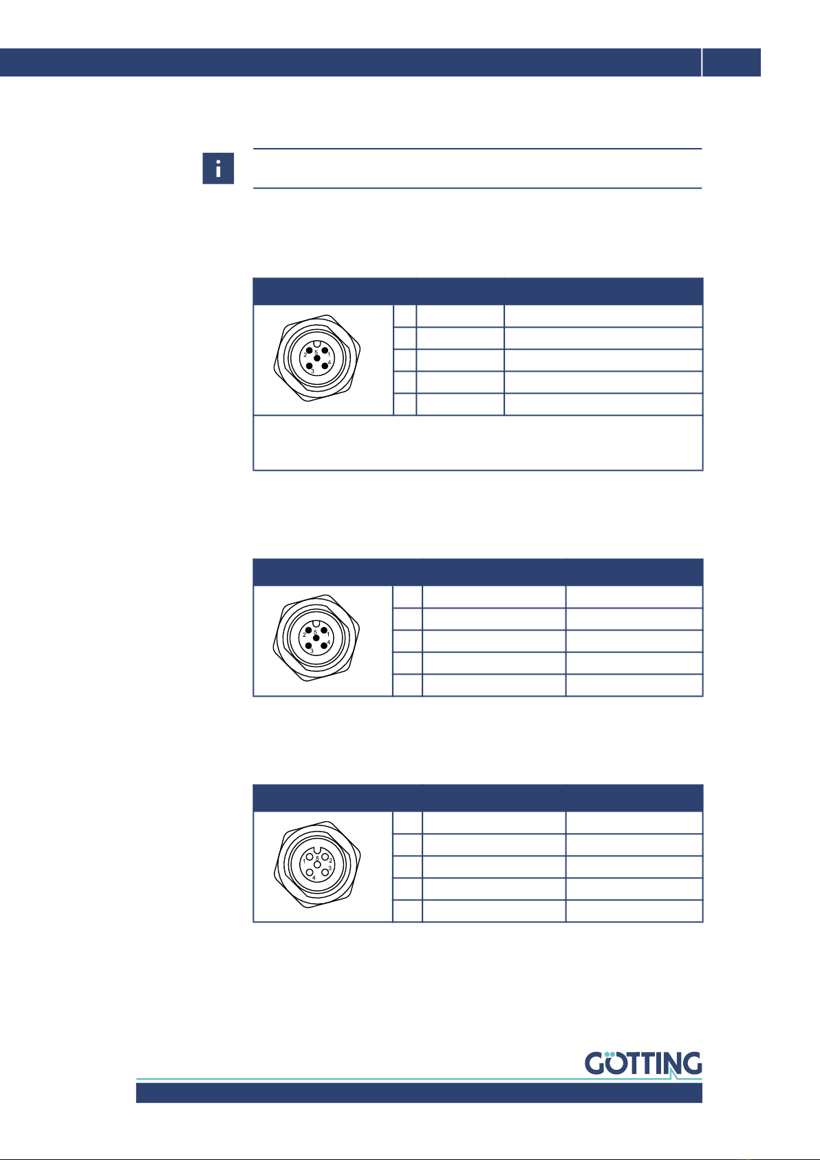
3.4 Pin Assignment............................................................................................................................................9
3.4.1 X1 (PWR/USB).........................................................................................................................................9
3.4.2 X2 (CAN) ....................................................................................................................................................9
3.4.3 X3 (CAN) ....................................................................................................................................................9
3.5 Switch-On Behavior ...............................................................................................................................10
3.6 LEDs...............................................................................................................................................................10
3.7 Error Messages.........................................................................................................................................11
4 Drift Compensation / Angle Reset............................................................12
4.1 Drift Compensation.................................................................................................................................12
4.2 Angle reset..................................................................................................................................................13
5 Configuration via USB ................................................................................14
5.1 USB Interface ............................................................................................................................................14
5.2 Terminal Program....................................................................................................................................15
5.3 Terminal Output In Monitor Mode ...................................................................................................15
5.3.1 Terminal Output for CAN Standard............................................................................................16
5.3.2 Terminal Output for CANopen® ..................................................................................................17
5.4 Logging (CSV)............................................................................................................................................18
5.5 Firmware Update.....................................................................................................................................18
6 CAN Bus Interface.......................................................................................20
6.1 Receiving Box............................................................................................................................................20
6.2 Transmitter Box........................................................................................................................................21
7 CANopen® Interface...................................................................................22
7.1 Description of the Process Data Objects (PDOs) ......................................................................22
7.1.1 Transmission Objects........................................................................................................................22
7.1.2 Reception Object ................................................................................................................................23
7.2 Heartbeat.....................................................................................................................................................23
7.3 Description of the Service Data Objects (SDOs) .......................................................................24
7.4 Object Directory .......................................................................................................................................24
7.4.1 Communication Specific Entries .................................................................................................24
7.4.2 Standardized Device Profile Range............................................................................................26
7.4.3 CANopen® Object Dictionary .......................................................................................................26
7.4.3.1 Device Type......................................................................................................................................26
7.4.3.2 Error Register...................................................................................................................................26
7.4.3.3 COB-ID SYNC message..............................................................................................................27
7.4.3.4 Device Name ...................................................................................................................................27
7.4.3.5 Hardware Version..........................................................................................................................27
7.4.3.6 Software Version ...........................................................................................................................27
7.4.3.7 Producer Heartbeat Time...........................................................................................................27
7.4.3.8 Identity Object.................................................................................................................................27
7.4.3.9 Receive PDO Parameter.............................................................................................................28
7.4.3.10 Mapping RPDO_1..........................................................................................................................28
7.4.3.11 Transmit PDO_1 Parameter .....................................................................................................28
Contents

Device Description HG G-84300ZD | English, Revision 10 | Date: 01.06.2022
4Table of Contents
7.4.3.12 Mapping TxPDO_1 ........................................................................................................................29
7.4.3.13 8 Bit Digital Input (transmitted in TxPDO 1) ......................................................................29
7.4.3.14 16 Bit Analog Inputs (transmitted in TxPDO 1)................................................................29
7.4.3.15 32 Bit Analog Inputs (transmitted in TxPDO 1)................................................................29
7.4.3.16 8 Bit Life Counter (transmitted in TxPDO 1)......................................................................30
8 Technical Data .............................................................................................31
9 List of Figures ..............................................................................................32
10 List of Tables................................................................................................33
11 Index..............................................................................................................34
12 Copyright and Terms of Liability...............................................................36
12.1 Copyright......................................................................................................................................................36
12.2 Exclusion of Liability ...............................................................................................................................36
12.3 Trade Marks and Company Names .................................................................................................36

Device Description HG G-84300ZD | English, Revision 10 | Date: 01.06.2022
5
About this Document – Chapter 1
For you to be able to use your product simply and safely this device description uses
consistent warning notices, symbols, terms and abbreviations. Those are described
in the following sections.
1.1 Warning Notices
In this device description warning notices appear before sequences of actions that
may lead to damage to persons or property. The listed actions for the danger preven-
tion have to be observed.
Warning notices have the following structure:
The warning symbol (warning triangle) indicates danger to life or risk of injury.
The signal word indicates the severity of the danger.
The paragraph kind or source of the danger names the kind or source of the
danger.
The paragraph consequences describes the consequences of not observing
the warning notice.
The paragraphs for danger prevention explain, how to avoid the danger.
The signal words have the following meanings:
About this Document
SIGNAL WORD
Kind or source of the danger
Consequences
Danger prevention
Table 1 Hazard classification according to ANSI Z535.6-2006
Warning Symbol, Signal Word Meaning
DANGER
DANGER indicates a hazardous situation
which, if not avoided, will result in death or
serious injury.
WARNING
WARNING indicates a hazardous situation
which, if not avoided, could result in death or
serious injury.
CAUTION
CAUTION indicates a hazardous situation
which, if not avoided, could result in minor or
moderate injury.
NOTICE
NOTICE indicates property damage: The
product or the environment could be dam-
aged.
1

Device Description HG G-84300ZD | English, Revision 10 | Date: 01.06.2022
6Chapter 1 – About this Document
1.2 Symbols
In this device description the following symbols and formatting are used:
The check mark lists a requirement.
The arrow shows an action step.
The indentation shows the result of an action or an action sequence.
Program texts and variables are indicated through the use of a fixed width
font.
Menu items and parameters are shown in cursive characters.
Whenever the pressing of letter keys is required for program entries, the
required etter eys are indicated as such (for any programs of Götting KG
small and capital letters are equally working).
If this information is ignored the product may not be operated in an optimal way.
Indicates one or more links to the Internet.
–www.goetting.de/xxx
–www.goetting.de/yyy
Indicates tips for easier operation of the product.

Device Description HG G-84300ZD | English, Revision 10 | Date: 01.06.2022
7
Introduction – Chapter 2
The Gyro HG G-84300ZD measures the angle of one rotation axis and permanently
outputs this angle via its interface, CAN/CANopen®. This information can be used
by a superordinate vehicle controller (not part of the scope of supply) to calculate the
current position of all types of vehicles, thus using the Gyro as part of an inertial nav-
igation system.
Figure 1 Photo HG G-84300ZD
The device is based on the latest generation of the MEMS technology. Compared to
other gyroscopes, it offers advantages like cost-performance ratio, low current con-
sumption, excellent robustness and long durability. In addition to the high quality
technology the Gyro offers an integrated Drift Compensation algorithm, that can be
used to further increase the accuracy of the angle measurement (see section 4.1 on
page 12).
Introduction
2

Device Description HG G-84300ZD | English, Revision 10 | Date: 01.06.2022
8Chapter 3 – Hardware
3.1 Alignment of the Measuring Axis
Figure 2 Sketch: Measuring axis
3.2 Dimensions
Figure 3 Sketch: Dimensions of the casing (in mm) / Mounting Drill holes
3.3 Mounting
On the front plate of the Gyro two cover plates can be removed. Then two mounting
drill holes can be reached (see picture above). When the gyro is mounted, the cover
plates should be re-attached.
Hardware
3
X
+
-
The angle measurement
for X increases when the
Gyro is rotated counter-
clockwise
Drill hole
Drill hole for M4 mounting screw
for M4
approx. 80
mounting
screw

Device Description HG G-84300ZD | English, Revision 10 | Date: 01.06.2022
9
Hardware – Chapter 3
3.4 Pin Assignment
3.4.1 X1 (PWR/USB)
5-pin M12 panel plug (A coded)
3.4.2 X2 (CAN)
5-pin M12 panel plug (A coded)
3.4.3 X3 (CAN)
5-pin M12 panel plug socket (A coded)
There is no terminating resistor (terminator) for the CAN bus in the device!
Table 2 Pin assignment X1 (PWR/USB)
Pin Signal Description
1 +Ub (24V) supply voltage
2 IN1 *) activate drift compensation *)
3 D+ USB
4 D- USB
5 GND supply ground
*) If a high level (24 V) is applied to this input, the Gyro calculates the drift compen-
sation (see section 4.1 on page 12). May only be started when the vehicle is
not moving!
Table 3 Pin assignment X2 (CAN)
Pin Signal Description
1 shield (chassis) ground casing
2 +Ub (24V) supply voltage
3 GND supply ground
4 CAN_H CAN high
5 CAN_L CAN low
Table 4 Pin assignment X3 (CAN)
Pin Signal Description
1 shield (chassis) ground casing
2 +Ub (24V) supply voltage
3 GND supply ground
4 CAN_H CAN high
5 CAN_L CAN low

Device Description HG G-84300ZD | English, Revision 10 | Date: 01.06.2022
10 Chapter 3 – Hardware
3.5 Switch-On Behavior
The gyro calibrates itself for 10 s after switching on (applying the supply voltage). It
must not be moved during this time. This also means that a vehicle in which the gyro
is installed must not be moved during this time.
3.6 LEDs
The CAN LED has a different meaning depending on whether the CAN mode is set
to CAN Standard or CANopen® (see section 5.3 on page 15).
WARNING
Uncontrolled drift
If the gyro is moved during the first 10 s after being switched on, the initialization
of the drift compensation that then takes place leads to incorrect values. If a
vehicle is subsequently track guided on the basis of the faulty values,
uncontrolled driving behavior or even leaving the track may occur.
Do not move the gyro during the first 10 s after switch-on.
If an increased drift can be detected or if there is a suspicion that the gyro was
moved within the first 10 s after switch-on:
Perform drift compensation (see chapter 4 on page 12) or
switch the gyro off and on again and do not move it for 10 s.
Table 5 Functions of the LEDs
LED Mode Color / Frequency Meaning
SYS Green / Steady light Normal operation
Red / Blinking Parameter error (s. Table 6)
SENS Green / Blinking Measuring active
Yellow / Flickering Drift compensation active
Green / Flickering Drift compensation completed
CAN CAN
Standard
Green / Steady light Communication OK
Red / Blinking Communication error (s. Table 6)
CANopen® Green / Flashing State: STOP
Green / Blinking State: Preoperational
Green / Steady light State: Operational
Red / Blinking Communication error (s. Table 6)

Device Description HG G-84300ZD | English, Revision 10 | Date: 01.06.2022
11
Hardware – Chapter 3
3.7 Error Messages
If an error occurs this is indicated by the LEDs (see above). The errors listed in the
table below can be shown. If the solution says that you should send the device to
Götting please contact us beforehand. Also please try to document, how and when
the error occurred.
Table 6 How to react in case of an error
Error Description Reaction
Parameter error Error in the parameter
memory when starting
the firmware program
–Start the monitor program (s. sec-
tion 5.3 on page 15) and save the
parameters
–Re-start the gyro (switch off supply
voltage and then turn it on again)
–If the error continues to happen
after the re-start send the Gyro to
the Götting service department
CAN communi-
cation error
The connection via the
CAN bus is interrupted
–Check the CAN settings in the
monitor program (s. section 5.3 on
page 15)
–Make sure the correct CAN mode is
selected (depending on the appli-
cation CAN Standard or
CANopen®)
–Check the Hardware (correct fitting
of cables, connectors and – if used
– the optional CAN terminator)
–Check the communication partners
on the CAN bus
–If the error can not be eliminated
send the Gyro to the Götting ser-
vice department

Device Description HG G-84300ZD | English, Revision 10 | Date: 01.06.2022
12 Chapter 4 – Drift Compensation / Angle Reset
4.1 Drift Compensation
Inherent to the technology of the Gyro is a drift. This drift depends on different vari-
ables and changes over time. In order to reduce the effect of the drift on the angle
calculation, the Gyro can perform a Drift Compensation whenever the vehicle is not
moving. It then calculates the amount of the current drift and – when the vehicle is
moving again – compensates the influence of this drift.
Figure 4 Drift compensation process
Using the inputs the vehicle controller (e.g. PLC) can tell the Gyro to activate the drift
compensation calculation whenever the vehicle is not moving. The PLC can then
check that drift compensation is active via the corresponding outputs. The user sees
it from a LED. The PLC then waits until the Gyro signals via the CAN Status Byte that
the drift compensation calculation is completed.
Drift Compensation / Angle Reset
As the accuracy of the angle measurement improves drastically when the Gyro can
use drift compensation it is advisable to let it perform the compensation calcula-
tion as often as possible.
WARNING
Uncontrolled drift
If the gyro is moved during drift compensation, it determines erroneous values. If
a vehicle is subsequently tracked on the basis of the faulty values, uncontrolled
driving behavior or even leaving the track may occur.
Do not move the gyro during drift compensation.
If an increased drift can be detected or if there is a suspicion that the gyro was
moved during drift compensation:
Perform drift compensation again or
switch the gyro off and on again and do not move it for 10 s.
4
Vehicle controller (e.g. )
sets the bit ( ) „Activate Dri
Compensation“ to
PLC
CAN
Vehicle has to stand still
Gyro sets the bit ( )
„Dri Compensation “ to
CAN
OK
Gyro sets output ( )
„Dri Compensation active“ to
CAN
Duration of Dri compensation: - Right aer switch-on of the device (self heating
of the sensor) or aer changes of the surrounding temperature:
Up to several minutes
- During normal operation: < 10 s
Time
0
0
0
1
1
2
1
1
3

Device Description HG G-84300ZD | English, Revision 10 | Date: 01.06.2022
13
Drift Compensation / Angle Reset – Chapter 4
The PLC can either turn off drift compensation when the OK signal comes or after a
defined interval. However make sure that it is turned off before the vehicle starts
moving again no matter whether the compensation calculation is finished or not. If
possible, let the vehicle stand still until the compensation calculation is completed.
4.2 Angle reset
The drift changes the absolute angle measurement over time. That means that if the
vehicle crosses the same place again after some time, the absolute angle output will
be different from the last time. This doesn‘t influence the validity of the actual angle
calculation. However it may be desirable to reset the angle to 0o when the vehicle
reaches defined points on the course. In order to do so the vehicle controller (e.g.
PLC) can trigger the Set angle to 0 command (CAN).
Figure 5 Angle reset process
Via CAN set the corresponding bit to 1, which also immediately sets the response in
the status bit to 1. At the same time the Gyro resets the angle. Then set the CAN bit
back to 0 until you want to reset the angle again. The status bit remains set as longs
as the trigger bit is set.
Vehicle controller (e.g. )
sets the Bit ( )
„Set angle to 0°“ to
PLC
CAN
Gyro sets the Bit ( )
„Angle set to 0°“ to
CAN
Time
0
0
1
1

Device Description HG G-84300ZD | English, Revision 10 | Date: 01.06.2022
14 Chapter 5 – Configuration via USB
5.1 USB Interface
The 5 pin connector X1 can be used to establish a connection with a PC. The PC
needs to have a USB interface.
Figure 6 Connection example: USB connection with a PC
The USB chip in the Gyro is addressed as a virtual serial interface (virtual COM Port).
Thus devices with USB interfaces can be configured using the same terminal pro-
grams (see below) that are used for RS 232 connections. Usually the virtual COM
Port driver is installed automatically in current versions of Microsoft® Windows®.
If the Gyro is not automatically detected as a virtual COM port after establishing the
connection the STM32 Virtual COM Port Driver (STSW-STM32102) has to be in-
stalled manually. The driver may be downloaded from the following address:
Configuration via USB
NOTICE
Damage to the gyro or other devices connected via USB
The USB interface does not have a leading ground contact. Plugging or
unplugging USB connectors while the voltage supply is connected can cause
voltage spikes that will damage devices connected via USB.
Always disconnect the gyro from the voltage supply before plugging or
unplugging USB connectors. This applies, for example, to the USB connector
on the computer and connector X1 on the gyro.
Götting offers the optional connection box M12-5-8-USB HG G-20960 that can be
used to interconnect the Gyro and the PC. The box allows to connect the gyro
using standard M12 cable.
You can find more information on the connection box at
http://goetting-agv.com/components/20960
http://www.st.com/en/development-tools/stsw-stm32102.html
5
USB adapter
(to be tailored
by the customer)
All other pins:
Do not connect
X1 Gyro
Computer (e.g.
or Laptop) with
interface
PC
USB
1
1
1
Ub (+24V)
Type A Type B
D+
D+
D-
D-
GND
GND
2
2
2
3
33
4
44
1
2
3
4
512
3
4
5
+–
External voltage supply

Device Description HG G-84300ZD | English, Revision 10 | Date: 01.06.2022
15
Configuration via USB – Chapter 5
5.2 Terminal Program
Every compatible terminal program that supports the ANSI emulation can be
used. Examples are HyperTerminal® and Tara Term®. HyperTerminal used to be part
of the scope of supply of earlier versions of Microsoft® Windows®. Additionally it
can be downloaded from the following address:
Start the terminal program on the PC and connect the Gyro with the PC (see above).
As soon as the connection is established successfully the Gyro‘s main menu accord-
ing to section 5.3 on page 15 appears in the terminal program.
Usually the port COM1 is used for the connection. This depends on the configuration
of the PC‘s interfaces. If another port is to be used then adjust it as follows (Hyper-
Terminal®):
1. Select Properties from the menu File (or lick the icon ). The following dialog
appears:
2. Use Connect using to select the respective port. Confirm with . Save the
altered values if you are asked for it while exiting HyperTerminal.
5.3 Terminal Output In Monitor Mode
The terminal output is different depending on whether the CAN interface is set to
CAN Standard or CANopen®. This can be changed via the monitor program.
In both CAN operating modes, a Status is output (see Figure 7 on page 16). The
status normally shows 0000 OK (0). A status 0 means an error in the MEMS
sensor.
https://www.hilgraeve.com/hyperterminal/
If the status outputs an error code, please make a note of the error code and con-
tact the Götting KG service department. To do this, use the contact data given on
the back of this device description or visit the following website.
www.goetting-agv.com/service

Device Description HG G-84300ZD | English, Revision 10 | Date: 01.06.2022
16 Chapter 5 – Configuration via USB
5.3.1 Terminal Output for CAN Standard
Figure 7 Screenshot: Terminal output in monitor mode / CAN Standard
Up to the dividing line the terminal shows the firmware version and status outputs.
Below the following functions can be called:
Reset angle to 0° (see 4.2 on page 13)
Activate or deactivate drift compensation (see 4.1 on page 12)
The following screenshot shows the drift compensation process inside the monitor
program. A percentage value counts up to 100 % then the drift is below the set
threshold defined by the parameter Drift margin (see below) and the drift compen-
sation can be deactivated again.
Figure 8 Screenshot: Drift compensation via monitor program
Data rate of output (value range: 1 to 100 [x 10ms])
Choose CAN mode (CAN STD / CANopen®)
CAN baudrate (125 kbit/s, 250 kbit/s, 500 kbit/s, 1 Mbit/s)
CAN identifier for receiver box
The two functions above are not used during normal operation of the monitor pro-
gram. They serve for the initial commissioning at Götting.

Device Description HG G-84300ZD | English, Revision 10 | Date: 01.06.2022
17
Configuration via USB – Chapter 5
CAN identifier for transmission box
Threshold under which the drift has to fall so that the Bit Drift compensation OK
is set to 1
Time with activated drift compensation after turn-on in order to determine a start
value
Save parameters permanently, necessary after each change
Update software, see section 5.5 on page 18
Log data (CSV), see section 5.4 on page 18
5.3.2 Terminal Output for CANopen®
Figure 9 Screenshot: Terminal output in monitor mode / CANopen®
Up to the dividing line the terminal shows the firmware version and status outputs.
Below the following functions can be called:
Reset angle to 0° (see 4.2 on page 13)
Activate or deactivate drift compensation (see 4.1 on page 12), the sequence as
analog to what happens with CAN Standard, see section 5.3.1 on page 16
Data rate of output (value range: 1 to 100 [x 10ms])
Choose CAN mode (CAN STD / CANopen®)
CAN baudrate (125 kbit/s, 250 kbit/s, 500 kbit/s, 1 Mbit/s)
, , , CANopen® specific settings
Threshold under which the drift has to fall so that the Bit Drift compensation OK
is set to 1
Time with activated drift compensation after turn-on in order to determine a start
value
Save parameters permanently, necessary after each change
Update software, see section 5.5 on page 18
Log data (CSV), see section 5.4 below

Device Description HG G-84300ZD | English, Revision 10 | Date: 01.06.2022
18 Chapter 5 – Configuration via USB
5.4 Logging (CSV)
With the command Log data in the monitor program (see above) the Gyro out-
puts structured data every 100 ms. Each line consists of several sections (columns)
that are divided by commas. Using the terminal program those values can be written
into a file (recorded). The structure of the file conforms to the CSV format (Comma
Separated Values), which can be imported into and analyzed in spreadsheet applica-
tions like Microsoft® Excel®.
The data is output as ASCII characters. The lines are closed with <CR LF>. Each line
consecutively includes the following values:
Rotation rate without drift,
Raw Data Sensor,
Bias,
Bias Counter,
Bias Timer,
Bias OK Counter,
Bias OK flag,
Temperature,
Scaling,
Sensor Status 1,
Sensor Status 2,
Sensor Status 3,
Sensor Status 4,
CAN Input Command,
CAN Output Angle,
CAN Output Temperature,
CAN Output Status
5.5 Firmware Update
Start the monitor program (see section 5.3 on page 15).
Put the device into the DFU Modus (Device Firmware Upgrade) with .
Close the connection via the COM port in the terminal program (disconnect).
For the following steps you need the firmware as a .dfu file as well as the software
DfuSe by ST Microelectronics. You can get the firmware file upon request from Göt-
ting. The software DfuSE is available from the following address:
Download DfuSE, install the program and start it. It starts into the Demo GUI
Mode which is sufficient to carry out the firmware update.
Use Choose to select the .dfu firmware file provided by Götting KG.
http://www.st.com/en/development-tools/stsw-stm32080.html

Device Description HG G-84300ZD | English, Revision 10 | Date: 01.06.2022
19
Configuration via USB – Chapter 5
Figure 10 Firmware Update – Choose file
If the status bar says File correctly loaded start the firmware update with
Upgrade.
Figure 11 Firmware Update – Start update
If the update is successful the status bar says Verify successful. Then leave DFU
mode and quit the program.
Figure 12 Firmware Update – Leave DFU Mode
Afterwards the connection in the terminal program can be re-established. Then start
the monitor program again.
Use Choose to select the .dfu file
As shown the DFU mode has
to be active
Start the update with Upgrade
.dfu correctly loades
Leave DFU mode
and Quit the program
Verify successful shows
that the update was successful

Device Description HG G-84300ZD | English, Revision 10 | Date: 01.06.2022
20 Chapter 6 – CAN Bus Interface
Annotations:
Angle: radian
Temperature: = Temperature in oC
6.1 Receiving Box
Length: 8 byte. This is the telegram that is sent from the vehicle controller (e.g. PLC)
to the Gyro.
Annotations for Command:
CAN Bus Interface
Table 7 CAN: Structure of the CAN receiving box
Byte Data
1 Command, see Table 8 below
2 –
3
4
5
6
7
8
Table 8 CAN: Structure of the command byte
Bit Description
1 De-/Activate drift compensation (see 4.1 on page 12)
2 Set angle to 0 (see 4.2 on page 13)
3 –
4
5
6
7
8
6
Value shown
8
--------------------------------
Table of contents
Other Gotting Industrial Equipment manuals
Popular Industrial Equipment manuals by other brands

Siemens
Siemens SIRIUS MCU 3RK4 32 Series operating instructions

ABB
ABB HT563811 Operation manual

Mototok
Mototok SPACER 8600 MA Operation manual

Thunderstone
Thunderstone THUNDER POWER TARP 7000 Operation instructions

Mid-West Instrument
Mid-West Instrument 522 Installation and operating instruction

Atlantic Boilers
Atlantic Boilers RS TURBOFLOW DN 32 S020+ operating & maintenance manual