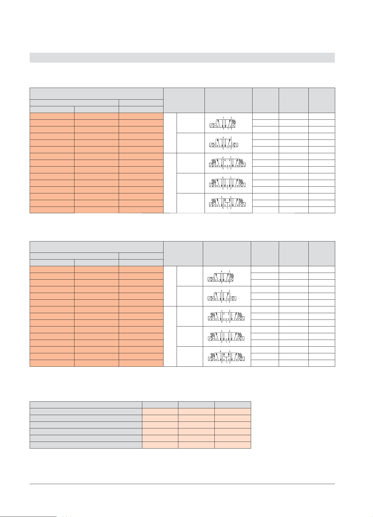
manuals.online logo
Brands
  1. Home
  2. •
  3. Brands
  4. •
  5. SMC Networks
  6. •
  7. Industrial Equipment
  8. •
  9. SMC Networks SYJ3000 User manual

SMC Networks SYJ3000 User manual


¿½À±¾¹Ð4.$¿Âñ³¼Ð¶Ã¸±¿²¿ºÀÁ±³¿¾±³¾¶Â¶¾¹¶öƾ¹È¶Â»¹Æ¹Á±¸½¶Á¾ÌÆ¹¸½¶¾¶¾¹º
5/2, 5/3 пневмораспределитель
с электропневматическим управлением
SYJ3000/5000/7000
y¿½À±»Ã¾±Ð»¿¾ÂÃÁĻǹÐ
y¹¸»±ÐÀ¿ÃÁ¶²¼Ð¶½±Ð½¿Ê¾¿ÂÃÍkÃξ¶Á´¿Â²¶Á¶´±Ïʶ¶¹ÂÀ¿¼¾¶¾¹¶
Технические характеристики
¢¶Á¹Ð 4:+ 4:+ 4:+
¢Á¶µ± ȹʶ¾¾Ìº·±Ã̺³¿¸µÄÆÂ¿µ¶Á·±¾¹¶½½±Â¼±¹¼¹²¶¸¾¶´¿
£¹ÀÄÀÁ±³¼¶¾¹Ð ®¼¶»ÃÁ¿À¾¶³½±Ã¹È¶Â»¿¶
¡±²¿È¹º
µ¹±À±¸¿¾
µ±³¼¶¾¹º
±
Â¿µ¾¿ÂÿÁ
ÄÀÁ±³¼¶¾¹¶½
_
Âµ³ÄÂÿÁ
ÄÀÁ±³¼¶¾¹¶½
_
 _ _ _
¡±²¿È¹ºµ¹±À±¸¿¾ö½À¶Á±ÃÄÁt¢ _
Á¶½Ð
ÂÁ±²±Ã̳±¾¹Ð
½Â
Â¿µ¾¿µ³ÄÂÿÁ
ÄÀÁ±³¼¶¾¹¶½
  
   
±»ÂȱÂÿñ
ÂÁ±²±Ã̳±¾¹Ð
Ç
Â¿µ¾¿µ³ÄÂÿÁ
ÄÀÁ±³¼¶¾¹¶½
 
  
ÂÀ¿½¿´±Ã¶¼Í¾¿¶ÁÄȾ¿¶ÄÀÁ±³¼¶¾¹¶ ¶²¼¿»¹ÁĶÃÂÐ
¿¾Ã±·¾¿¶À¿¼¿·¶¾¹¶ Á¿¹¸³¿¼Í¾¿¶
®¼¶»ÃÁ¹È¶Â»¹ºÁ±¸Ë¶½ Æ»¼¶½½¾Ìº
-Á±¸Ë¶½
Æ»¼¶½½¾Ìº-Á±¸Ë¶½
Æ»¼¶½½¾Ìº%*/Á±¸Ë¶½
±ÀÁз¶¾¹¶ 7%$
7"$
¿ÀÄ»À¿¾±ÀÁз¶¾¹Ï ¿Ã¾¿½¹¾±¼Í¾¿´¿¸¾±È¶¾¹Ð
¿ÃÁ¶²¼Ð¶½±Ð
½¿Ê¾¿ÂÃÍÃ
%$ _ _
"$ 
¢Ã¶À¶¾Í¸±Ê¹ÃÌ *1
¼±ÂÂ¹¸¿¼Ðǹ¹ #
»Á¿´±É¶¾¹¶ ¢Ã±¾µ±Áþ¿¶¹ÂÀ¿¼¾¶¾¹¶µ¼Ð%*/Á±¸Ë¶½±kÀ¿¸±ÀÁ¿ÂÄ
¾µ¹»±Ã¿ÁÁ±²¿È¶´¿¿Âÿо¹Ð ¢Ã±¾µ±Áþ¿¶¹ÂÀ¿¼¾¶¾¹¶µ¼Ð%*/Á±¸Ë¶½±kÀ¿¸±ÀÁ¿ÂÄ
Á¹ö½À¶Á±ÃÄÁ¶t$±ÀÁ¹¾¿½¹¾±¼Í¾¿½¾±ÀÁз¶¾¹¹
SYJ3000
SYJ5000
SYJ7000
Номер для заказа
Номер для заказа SYJ3000
¢±½¿ÂÿÐö¼Í¾Ìº½¿¾Ã±·¹¼¹½¿¾Ã±·¾±À¼¹Ã¶À¾¶³½¿Á±ÂÀÁ¶µ¶¼¹Ã¶¼¶º
Á¹¾Ç¹Àµ¶ºÂó¹Ð ¿½¶Áµ¼Ð¸±»±¸± ¤Â¼¿³¾¿¶¿²¿¸¾±È¶¾¹¶ Á¹Â¿¶µ
Á±¸½¶Á
¡±ÂÆ¿µ
¾¿Á½¼½¹¾
¶Â
´

µ¾¿ÂÿÁ¿¾¾¶¶
ÄÀÁ±³¼¶¾¹¶ 4:+-6.2
.


³ÄÂÿÁ¿¾¾¶¶
ÄÀÁ±³¼¶¾¹¶ 4:+-6.2 

±»ÁÌÃ̺
Ƕ¾ÃÁ 4:+-6.2 

ûÁÌÃ̺
Ƕ¾ÃÁ 4:+-6.2 
§¶¾ÃÁÀ¿µ
µ±³¼¶¾¹¶½ 4:+-6.2 

Номер для заказа
SYJ3000/5000/7000
5/2, 5/3 пневмораспределитель с электропневматическим управлением
Номер для заказа SYJ5000
¢±½¿ÂÿÐö¼Í¾Ìº½¿¾Ã±·¹¼¹½¿¾Ã±·¾±À¼¹Ã¶À¾¶³½¿Á±ÂÀÁ¶µ¶¼¹Ã¶¼¶º
¿½¶Áµ¼Ð¸±»±¸±
Á¹¾Ç¹Àµ¶ºÂó¹Ð ¤Â¼¿³¾¿¶¿²¿¸¾±È¶¾¹¶
Á¹Â¿¶µ
Á±¸½¶Á

¡±ÂÆ¿µ
¾¿Á½¼½¹¾
¶Â´
¡±¸Ë¶½
Â»±²¶¼¶½
%*/Á±¸Ë¶½
7%$ 7"$
©Ã¶»¶ÁÂ»±²¶¼¶½ %*/Á±¸Ë¶½ %*/Á±¸Ë¶½
4:+-6.2 4:+:0.2 4:+:0.2

µ¾¿
ÂÿÁ¿¾¾¶¶
ÄÀÁ±³¼¶¾¹¶
.  
4:+-6$2 4:+:0$2 4:+:0$2 $  
4:+-6.2 4:+:0$2 4:+:0$2 $  
4:+-6.2 4:+:0.2 4:+:0.2 ³Ä
ÂÿÁ¿¾¾¶¶
ÄÀÁ±³¼¶¾¹¶
.  
4:+-6.2 4:+:0$2 4:+:0$2 $  
4:+-6.2 4:+:0$2 4:+:0$2 $  
4:+-6.2 4:+:0.2 4:+:0.2

±»ÁÌÃ̺
Ƕ¾ÃÁ
.  
4:+-6.2 4:+:0$2 4:+:0$2 $  
4:+-6.2 4:+:0$2 4:+:0$2 $  
4:+-6.2 4:+:0.2 4:+:0.2 ûÁÌÃ̺
Ƕ¾ÃÁ
.  
4:+-6.2 4:+:0$2 4:+:0$2 $  
4:+-6.2 4:+:0$2 4:+:0$2 $  
4:+-6.2 4:+:0.2 4:+:0.2 §¶¾ÃÁÀ¿µ
µ±³¼¶¾¹¶½
.  
4:+-6.2 4:+:0$2 4:+:0$2 $  
4:+-6.2 4:+:0$2 4:+:0$2 $  
ÌÂÃÁ¿Á±¸Ë¶½¾¿¶¿¶µ¹¾¶¾¹¶¾±ÀÁ¹½¶Á¢kø
Номер для заказа SYJ7000
¢±½¿ÂÿÐö¼Í¾Ìº½¿¾Ã±·¹¼¹½¿¾Ã±·¾±À¼¹Ã¶À¾¶³½¿Á±ÂÀÁ¶µ¶¼¹Ã¶¼¶º
¿½¶Áµ¼Ð¸±»±¸±
Á¹¾Ç¹Àµ¶ºÂó¹Ð ¤Â¼¿³¾¿¶¿²¿¸¾±È¶¾¹¶
Á¹Â¿¶µ
Á±¸½¶Á

¡±ÂÆ¿µ
¾¿Á½¼½¹¾
¶Â´
¡±¸Ë¶½
Â»±²¶¼¶½
%*/Á±¸Ë¶½
7%$ 7"$
©Ã¶»¶ÁÂ»±²¶¼¶½ %*/Á±¸Ë¶½ %*/Á±¸Ë¶½
4:+-62 4:+:02 4:+:02

µ¾¿
ÂÿÁ¿¾¾¶¶
ÄÀÁ±³¼¶¾¹¶
  
4:+-6$2 4:+:0$2 4:+:0$2 $  
4:+-6$2 4:+:0$2 4:+:0$2 $  
4:+-62 4:+:02 4:+:02 ³Ä
ÂÿÁ¿¾¾¶¶
ÄÀÁ±³¼¶¾¹¶
  
4:+-6$2 4:+:0$2 4:+:0$2 $  
4:+-6$2 4:+:0$2 4:+:0$2 $  
4:+-62 4:+:02 4:+:02

±»ÁÌÃ̺
Ƕ¾ÃÁ
  
4:+-6$2 4:+:0$2 4:+:0$2 $  
4:+-6$2 4:+:0$2 4:+:0$2 $  
4:+-62 4:+:02 4:+:02 ûÁÌÃ̺
Ƕ¾ÃÁ
  
4:+-6$2 4:+:0$2 4:+:0$2 $  
4:+-6$2 4:+:0$2 4:+:0$2 $  
4:+-62 4:+:02 4:+:02 §¶¾ÃÁÀ¿µ
µ±³¼¶¾¹¶½
  
4:+-6$2 4:+:0$2 4:+:0$2 $  
4:+-6$2 4:+:0$2 4:+:0$2 $  
ÌÂÃÁ¿Á±¸Ë¶½¾¿¶¿¶µ¹¾¶¾¹¶¾±ÀÁ¹½¶Á¢kø
ó¶Ã¾Ì¶ȱÂùÁ±¸Ë¶½¿³¸±»±¸Ì³±ÏÃÂÐ¿Ãµ¶¼Í¾¿
Номера для заказа принадлежностей для монтажа
£¹À¿Á±¸½¶Á   
Á¿»¼±µ»± 4:+ %95 %95
¹¾Ãµ¼Ð»Á¶À¼¶¾¹ÐÀ¾¶³½¿Á±ÂÀÁ¶µ¶¼¹Ã¶¼Ð 4: .Y .Y
¹¾Ãµ¼Ð»Á¶À¼¶¾¹Ð¸±´¼ÄÉ»¹ 4: .Y .Y
Á¹½¶È±¾¹Ð¼ÐÄÂñ¾¿³»¹¿µ¾¿´¿À¾¶³½¿Á±ÂÀÁ¶µ¶¼¹Ã¶¼Ð¹¼¹¿µ¾¿º¸±´¼ÄÉ»¹¾¶¿²Æ¿µ¹½¿¸±»±¸Ì³±ÃÍµ³±³¹¾Ã±
A
4:+2A
¾µ¹³¹µÄ±¼Í¾Ìº³ÌÀÄ»³¿¸µÄƱÂÄÀ¼¿Ã¾¶¾¹Ð½¹¹³¹¾Ã±½¹ k4:+'"
4:+ 3A
±´¼ÄÉ»± 4:+ 4:+
-5A

¿½À±¾¹Ð4.$¿Âñ³¼Ð¶Ã¸±¿²¿ºÀÁ±³¿¾±³¾¶Â¶¾¹¶öƾ¹È¶Â»¹Æ¹Á±¸½¶Á¾ÌÆ¹¸½¶¾¶¾¹º
SYJ3000/5000/7000
5/2, 5/3 пневмораспределитель с электропневматическим управлением
Ответные части разъемов (заказываются отдельно)
Ответные части разъемов
²¿¸¾±È¶¾¹¶ ¼¹¾±
»±²¶¼Ð
¿½¶Áµ¼Ð¸±»±¸±
7%$ 7"$
±²¶¼Í²¶¸¿²¿¼¿È»¹
¹ÀÁ¶µ¿ÆÁ±¾¹Ã¶¼Í¾¿´¿
»¿¼À±È»±
 4:" 4:"
 4:" 4:"
 4:" 4:"
±²¶¼ÍÂ¿²¿¼¿È»¿º
¹ÀÁ¶µ¿ÆÁ±¾¹Ã¶¼Í¾Ì½
»¿¼À±È»¿½
 4:" k
 4:" k
 4:" k
DIN-разъем
À¹Â±¾¹¶ ¿½¶Áµ¼Ð¸±»±¸±
7%$ 7"$
¶¸¹¾µ¹»±Ã¿Á±Á±²¿È¶´¿¿Âÿо¹Ð
²¶¸¹Â»Á¿´±É¶¾¹Ð
,
¢¹¾µ¹»±Ã¿Á¿½Á±²¿È¶´¿¿Âÿо¹Ð
Â¹Â»Á¿´±É¶¾¹¶½
, ,
¢Æ¶½ÄÀ¿µ»¼Ïȶ¾¹Ð½¾±ÂÃÁ
Запасной элемент включения
£¹À ±ÀÁз¶¾¹¶ ¿½¶Áµ¼Ð¸±»±¸±
¡±¸Ë¶½Â»±²¶¼¶½ %*/Á±¸Ë¶½
4:+ 7%$ 7-062 k
4:+ 7:02
4:+
4:+ 7"$ k 7:02
4:+
Конструкция
Спецификация
¿¸ ²¿¸¾±È¶¾¹¶ ±Ã¶Á¹±¼
 ¿ÁÀÄÂÀ¾¶³½¿Ç¹¼¹¾µÁ± ¼Ï½¹¾¹º
 Á¿½¶·ÄÿȾ±Ðµ¶Ã±¼Í ¿¼¹±Ç¶Ã±¼Í
 ¿¾Ç¶³±ÐÀ¼±Âù¾± ¼Ï½¹¾¹º
 ¿Áɶ¾ÍÄÀÁ±³¼¶¾¹Ð ¿¼¹±Ç¶Ã±¼Í
 ¿¼¿Ã¾¹» ¶Á·Âñ¼Í
 ÁÄ·¹¾± k
 ±ÃÄÉ»± k
£¿¼Í»¿µ¼Ð¶Á¹º4:+4:+
5/2 с односторонним управлением
5/2 с двусторонним управлением 5/3 в среднем положении открыт/закрыт
»Á±Â¾Ìº ȶÁ¾Ìº ¶Á̺

SYJ3000/5000/7000
5/2, 5/3 пневмораспределитель с электропневматическим управлением
Размеры SYJ3000
SYJ3120 Штекер с кабелем
SYJ3220 Штекер с кабелем

¿½À±¾¹Ð4.$¿Âñ³¼Ð¶Ã¸±¿²¿ºÀÁ±³¿¾±³¾¶Â¶¾¹¶öƾ¹È¶Â»¹Æ¹Á±¸½¶Á¾ÌÆ¹¸½¶¾¶¾¹º
SYJ3000/5000/7000
5/2, 5/3 пневмораспределитель с электропневматическим управлением
Размеры SYJ3000
Номер для заказа многосекционной плиты пневмораспределителей SYJ3000
Штекер с кабелемSYJ3320/3420/3520
¿¼³¿¶»Ç¹º ¿½¶Áµ¼Ð¸±»±¸±
44:+'
44:+'
44:+'
44:+'
44:+'
44:+'
44:+'
44:+'
 44:+'
 44:+'
 44:+'
 44:+'
 44:+'
 44:+'
 44:+'
 44:+'
 44:+'
 44:+'
 44:+'

SYJ3000/5000/7000
5/2, 5/3 пневмораспределитель с электропневматическим управлением
Размеры многосекционной плиты пневмораспределителей SYJ3000
¿¼³¿
¶»Ç¹º 
-                   
-                   
Штекер с кабелем

¿½À±¾¹Ð4.$¿Âñ³¼Ð¶Ã¸±¿²¿ºÀÁ±³¿¾±³¾¶Â¶¾¹¶öƾ¹È¶Â»¹Æ¹Á±¸½¶Á¾ÌÆ¹¸½¶¾¶¾¹º
SYJ3000/5000/7000
5/2, 5/3 пневмораспределитель с электропневматическим управлением
Размеры SYJ5000
SYJ5120
DIN-разъемШтекер с кабелем
SYJ5220

SYJ3000/5000/7000
5/2, 5/3 пневмораспределитель с электропневматическим управлением
Размеры SYJ5000
Номер для заказа многосекционной плиты пневмораспределителей SYJ5000
SYJ5320/5420/5520
DIN-разъемШтекер с кабелем
¿¼³¿¶»Ç¹º ¿½¶Áµ¼Ð¸±»±¸±
44:+'
44:+'
44:+'
44:+'
44:+'
44:+'
44:+'
44:+'
 44:+'
 44:+'
 44:+'
 44:+'
 44:+'
 44:+'
 44:+'
 44:+'
 44:+'
 44:+'
 44:+'

¿½À±¾¹Ð4.$¿Âñ³¼Ð¶Ã¸±¿²¿ºÀÁ±³¿¾±³¾¶Â¶¾¹¶öƾ¹È¶Â»¹Æ¹Á±¸½¶Á¾ÌÆ¹¸½¶¾¶¾¹º
SYJ3000/5000/7000
5/2, 5/3 пневмораспределитель с электропневматическим управлением
Размеры многосекционной плиты пневмораспределителей SYJ5000
¿¼³¿
¶»Ç¹º 
-                   
-                   
Встроенное
быстроразъемное
соединение
DIN-разъемШтекер с кабелем

SYJ3000/5000/7000
5/2, 5/3 пневмораспределитель с электропневматическим управлением
DIN-разъемШтекер с кабелем
Размеры SYJ7000
SYJ7120
SYJ7220
DIN-разъемШтекер с кабелем

¿½À±¾¹Ð4.$¿Âñ³¼Ð¶Ã¸±¿²¿ºÀÁ±³¿¾±³¾¶Â¶¾¹¶öƾ¹È¶Â»¹Æ¹Á±¸½¶Á¾ÌÆ¹¸½¶¾¶¾¹º
Размеры SYJ7000
SYJ3000/5000/7000
5/2, 5/3 пневмораспределитель с электропневматическим управлением
Номер для заказа многосекционной плиты пневмораспределителей SYJ7000
DIN-разъемШтекер с кабелем
SYJ7320/7420/7520
Размер присоединительных
отверстий P и R =1/8
Размер присоединительных
отверстий P и R =1/4
¿¼³¿¶»Ç¹º ¿½¶Áµ¼Ð¸±»±¸±
44:+'
44:+'
44:+'
44:+'
44:+'
44:+'
44:+'
44:+'
 44:+'
 44:+'
 44:+'
 44:+'
 44:+'
 44:+'
¿¼³¿¶»Ç¹º ¿½¶Áµ¼Ð¸±»±¸±
44:+'
44:+'
44:+'
44:+'
44:+'
44:+'
44:+'
44:+'
 44:+'
 44:+'
 44:+'
 44:+'
 44:+'
 44:+'

SYJ3000/5000/7000
5/2, 5/3 пневмораспределитель с электропневматическим управлением
Размеры многосекционной плиты пневмораспределителей SYJ7000
DIN-разъемШтекер с кабелем
¿¼³¿¶»Ç¹º 
-              
-              
Встроенное
быстроразъемное
соединение
4/5 Port Solenoid Valve
Improved pilot valve
Pilot valve cover is stronger using stainless steel.
Mounting thread is also reinforced from size M1.7 to M2.
Flow Characteristics
SYJ3000
SYJ5000
SYJ7000
0.46
0.83
2.9
0.36
0.32
0.35
0.12
0.21
0.74
Series Flow characteristics
C [(dm3/s·bar)] bCv
Cover (stainless steel)
CAT.ES11-84
B
For AC

100 VAC / Hz
110 VAC / Hz
200 VAC / Hz
220 VAC / Hz
Sonic conductance:
C [dm3/(s.bar)]
Front matter 1
SYJ3000
SYJ5000
SYJ7000
SYJ3000
SYJ5000
SYJ7000
50
60
50
50
50
60
60
60
Rubber Seal
4/5 Port Solenoid Valve
Series SYJ3000/5000/7000
Variations
Series
Grommet
For DC
Note) All AC voltage models have built-in surge voltage suppressor.
Type of
actuation
2 Position
Single
Double
3 Position
Voltage Electrical entry
Option
With light/surge
voltage suppressor
Manual
override
{}
{ }
0.47
4/2  5/3
(A/B  EA/EB)
{}
2.4
4/2  5/3
(A/B  EA/EB)
{}
0.46
4/2  5/3
(A/B  EA/EB)
{}
0.83
4/2  5/3
(A/B  EA/EB)
{}
2.9
4/2  5/3
(A/B  EA/EB)
For DC
 24 VDC
12 VDC
6 VDC
5 VDC
3 VDC
L plug connector
M plug connector
Note)
For AC
Body portedBase mounted
DIN terminal
M8 connector
Effective area
0.9 mm2
4/2  5/3
(A/B  EA/EB)
(SYJ5000, 7000
only)
–+
+–
–+
Closed
center
Exhaust
center
Pressure
center
 With light/surge
voltage suppressor
 Non-locking
push type
 Push-turn
locking
slotted type
 Push-turn
locking
lever type
 With surge voltage
suppressor
 With light/ surge
voltage suppressor
P. 1
P. 1
P. 2 3
P. 2 3
P. 4 7
P. 4 7
R
P
-+-+
A
B
R
P
-+ -+
RR
P
-+ -+
Series SYJ3000/5000/7000
SYJ3000
SYJ5000
SYJ7000
SYJ3000
SYJ5000
SYJ7000
M3

—
—

—
—
—
—
—
Manifold Variations
Valve series
A, B port size
With one-touch fitting
Applicable tubing O.D
—
—

—
—
—
—


ø4
—

—

—

—
—
—
M5
—

—

—


—
—
ø6
—


—
—

—

—
ø8
—
—

—
—
—
—

—
N3
—

—

—

—
—
—
N7
—


—
—

—

—
N9
—
—

—
—
—
—

—
—

—
—


—


—


—
—
—
—






—

—
—
—
Manifold option
Individual
SUP
spacer
assembly
Individual
EXH
spacer
assembly
Interface
regulator
Flat ribbon cable manifold
Mixed mounting of 3 port
valves and 4, 5 port valves
Type 21P
Individual SUP
spacer assembly
P
3 port valve
4, 5 port valve
Interface
regulator
Type 32P
Base mounted
Body ported
A, B port
R port
P port
A, B port
R port
P port
A, B port
R port
P port
A, B port
P port
R port
A, B port
P port
R port
Individual EXH
spacer assembly
R1
R2
(P port
regulation)
(P port
regulation)
A, B port
location
Top
Side
Bottom
Side
Bottom
Side
Bottom
Body portedBase mounted
1/8
For detailed specifications about
SYJ3000, refer to page 14. For
SYJ5000, refer to page 38, and for
SYJ7000, refer to page 61.
R
P
-+ -+
A
B
R
P
-+ -+
A
B
B
Front matter 2
Rubber Seal
4/5 Port Solenoid Valve
Series SYJ3000
Specifications
Fluid
Operating pressure range
MPa
Ambient and fluid temperature (C)
Response time (ms)
(at 0.5 MPa)
Max. operating
frequency (Hz)
Manual override (Manual operation)
Pilot exhaust method
Lubrication
Mounting orientation
Shock/Vibration resistance (m/s2)
Enclosure
2 position single
2 position double
3 position
2 position single, double
3 position
2 position single, double
3 position
Air
0.15 to 0.7
0.1 to 0.7
0.2 to 0.7
–10 to 50 (No freezing. Refer to back page 3.)
15 or less
30 or less
10
3
Non-locking push type, Push-turn locking slotted type, Push-turn locking lever type
Individual exhaust for the pilot valve, Common exhaust for the pilot and main valve
Not required
Unrestricted
150/30
Dust proof (∗M8 connector conforms to IP65.)
2 position single
2 position double
(B)
2
1
(P) 1
(P)
3
(R) 3
(R)
5
(R)
(A)
4(B)
2(A)
4
1
(P) 3
(R)
(B)
2(A)
4
1
(P) 3
(R)
(B)
2(A)
4
1
(P) 3
(R)
(B)
2(A)
4
1
(P) 3
(R)
(B)
2(A)
4
(B)
2
1
(P)
3
(R) 5
(R)
(A)
4
(B)
2
1
(P)
3
(R) 5
(R)
(A)
4
(B)
2
1
(P)
3
(R) 5
(R)
(A)
4
(B)
2
1
(P)
3
(R) 5
(R)
(A)
4
2 position single
2 position double
3 position closed center
3 position exhaust center
3 position pressure center 3 position pressure center
3 position exhaust center
3 position closed center
JIS Symbol
5 port 4 port (manifold)
Note 1)
Note 2)
Solenoid Specifications
Bracket Mounting
Electrical entry
Coil rated voltage (V)
Allowable voltage fluctuation
Power consumption (W)
Apparent power VA ∗
Surge voltage suppressor
Indicator light
DC
AC 50/60 Hz
AC
DC Standard
With power saving circuit
100 V
110 V
[115 V]
200 V
220 V
[230 V]
Gromet (G), (H), L plug connector (L),
M plug connector (M), M8 connector (W)
24, 12, 6, 5, 3
100, 110, 200, 220
10% of rated voltage ∗
0.35 (With light: 0.4)
0.1 (With light only)
0.78 (With light: 0.81)
0.86 (With light: 0.89)
[0.94 (With light: 0.97)]
1.18 (With light: 1.22)
1.30 (With light: 1.34)
[1.42 (With light: 1.46)]
Diode (Non-polarity type: Valistor)
LED
∗In common between 110 VAC and 115 VAC, and between 220 VAC and 230 VAC.
∗For 115 VDC and 230 VDC, the allowable voltage is –15% to +5% of rated voltage.
∗S, Z and T type (with power saving circuit) should be used within the following allowable voltage fluctuation range due to
a voltage drop caused by the internal circuit. S and Z type: 24 VDC: –7% to +10%, 12 VDC: –4% to +10%
T type: 24 VDC: –8% to +10%, 12 VDC: –6% to +10%
∗Based on IEC60529
Note 1)Based on dynamic performance test, JIS B 8375-1981. (Coil temperature: 20C, at rated voltage, without surge
voltage suppressor)
Note 2) Impact resistance: No malfunction occurred when it is tested in the axial direction and at the right angles to the
main valve and armature in both energized and de-energized states every once for each
condition. (Value in the initial state)
Vibration resistance: No malfunction occurred in one sweep test between 45 and 2000 Hz. Test was performed to
axis and right angle directions of the main valve when pilot signal is ON and OFF. (Value in
the initial state)
q Insert the lower hook of the mounting bracket into
the groove on the bottom of the valve as shown.
w Press the valve and mounting bracket together
until the upper hook of the bracket snaps into
place in the groove on top of the valve.
Body ported
Base mounted
Made to Order
(For details, refer to page 79.)
For details about certified products conforming to
international standards, visit us at www.smcworld.com.
1
Series SYJ3000
Flow Characteristics/Weight
Cylinder Speed Chart
2
C [dm3/(s·bar)]
bCv
Weight (g) Note 3, 4)
Grommet
63 (37)
81 (55)
84 (58)
37
55
58
37
55
58
L/M plug
connector
Port size
Type of actuationValve model
C [dm3/(s·bar)]
bCv
Flow characteristics Note 2)
Effective
area
(mm
2
)
14/2 (PA/B)
4, 2
(A, B)
1, 5, 3
(P, EA, EB)
4/25/3 (A/BEA/EB)
62 (36)
79 (53)
82 (56)
36
53
56
36
53
56
M8
connector
67 (41)
89 (63)
92 (66)
41
63
66
41
63
66
Note 1) Dedicated for manifold base. For details, refer to page 11.
Note 2) [ ] denotes the normal position. Exhaust center: 4/2 5/3, Pressure center: 1 4/2
Note 3) ( ): Without sub-plate.
Note 4) For DC voltages. For AC voltages add 3 g to the weight of the single solenoid and 6 g to the
weight of the double solenoid and 3 position types.
SYJ314
SYJ324
SYJ334
SYJ344
SYJ354
SYJ312
SYJ322
SYJ332
SYJ342
SYJ352
SYJ313
SYJ323
SYJ333
SYJ343
SYJ353
Single
Double
Closed center
Exhaust center
Pressure center
Single
Double
Closed center
Exhaust center
Pressure center
Single
Double
Closed center
Exhaust center
Pressure center
0.46
0.47
0.36
0.58 [0.32]
0.36
0.33
0.39
0.42 [0.33]
0.12
0.12
0.10
0.16 [0.080]
0.46
0.47
0.59 [0.40]
0.46
0.35
0.31
0.43 [0.33]
0.32
0.12
0.12
0.16 [0.11]
0.11
—
—
—
—
0.9
—
—
—
—
2 position
3 position
2 position
3 position
2 position
3 position
M3 x 0.5
M5 x 0.8
M5 x 0.8
M3 x 0.5
M5 x 0.8
1/8
Body Ported
Series
SYJ3120-M3
Average
speed
(mm/s)
Bore size
Series CJ2
Pressure 0.5 MPa
Load rate: 50%
Stroke 60 mm
Series CM2
Pressure 0.5 MPa
Load rate: 50%
Stroke 300 mm
ø6 ø10 ø16 ø20 ø25 ø32 ø40
Perpendicular, upward actuation
Horizontal actuation
800
700
600
500
400
300
200
100
0
Series
SYJ3140-M5
Average
speed
(mm/s)
Bore size
Series CJ2
Pressure 0.5 MPa
Load rate: 50%
Stroke 60 mm
Series CM2
Pressure 0.5 MPa
Load rate: 50%
Stroke 300 mm
ø6 ø10 ø16 ø20 ø25 ø32 ø40
Perpendicular, upward actuation
Horizontal actuation
800
700
600
500
400
300
200
100
0
Base Mounted
SYJ3120-M3
Body ported
Tubing bore x Length
Speed controller
Silencer
Series CJ2 Series CM2
ø4 x 1 m
AS1301F-04
AN120-M5
Conditions
SYJ3140-M5
Base mounted
Tubing bore x Length
Speed controller
Silencer
Series CJ2 Series CM2
ø6 x 1 m
AS2301F-06
AN120-M5
AS2001F-06
5 port
Base mounted
(with sub-plate)
Note 1)
4 Port
Base mounted
(For manifold
base only)
5 port
Body ported
Use as a guide for selection.
Please confirm the actual conditions with SMC
Sizing Program.
∗Cylinder is in extending. Speed controller is meter-out, which is directly connected with cylinder and its needle is fully opened.
∗Average speed of cylinder is obtained by dividing the full stroke time by the stroke.
∗Load factor: ((Load weight x 9.8) /Theoretical force) x 100%
Series SYJ3000
SYJ3 3 5 M
SYJ3 4 M
2
2
1
2
3
4
5
2 position single solenoid
2 position double solenoid
3 position closed center
3 position exhaust center
3 position pressure center
5
0
0
SYJ3 2 5 M1 M30
5
6
V
S
R
24 VDC
12 VDC
6 VDC
5 VDC
3 VDC
1
2
3
4
100 VAC
200 VAC
110 VAC [115 VAC]
220 VAC [230 VAC]
For manifold type
31, S31, 32, S32
5port
(Type 20 Manifold)
Body ported
Base mounted
(4 port)
Base mounted
(5 port)
5port
For sub-plate,
manifold type 41, S41, 46, S46
4 port Port size
Nil: Without sub-plate
(With gasket and screws)
M5:With M5 port sub-plate
Manual override
Nil: Non-locking push type
D:
Push-turn locking slotted type
E:
Push-turn locking lever type
Type of actuation Nil
S
Z
R
U
Without light/surge voltage suppressor
With surge voltage suppresor
With light/surge voltage suppressor
With surge voltage suppressor (Non-polar type)
With light/surge voltage suppressor (Non-polar type)
Light/surge voltage suppressor Bracket
Body option
Rated voltage
DC AC (50/60 Hz)
Electrical entry
∗LN, MN type: with 2 sockets.
∗For connector cable of M8 connector, refer to back page 10.
Note 1) Enter the cable length symbols in . Please be sure
to fill in the blank referring to back page 10.
24, 12, 6, 5, 3 VDC
100,110, 200, 220 VAC
Grommet
L plug connector
M plug connector
(Manifold use only)
Nil
T
Standard
With power saving circuit
(24, 12 VDC only)
Coil specifications
24, 12, 6, 5, 3 VDC
M8 connector
Note) When placing an order for body ported
solenoid valve as a single unit, mounting
bolt for manifold and gasket are not
attached. Order them separately, if
necessary. (For details, refer to page 15.)
How to Order
+
–
+
–
+
–
+
–
+–
+–
∗For type W, DC voltage is only available.
∗
For AC voltage valves there is no “S” option.
It is already built-in to the rectifier circuit.
∗
For type “R” and “U”, DC voltage is only
available.
∗
Power saving circuit is only available in the
"Z" type.
Single Double
-+
0:Pilot valve individual
exhaust for the pilot
valve
3:Common exhaust type
for main and pilot valve
∗Power saving circuit
is not available in the
case of Wtype.
G:Lead wire
length 300 mm
H:Lead wire
length 600 mm
L:
With lead wire
(Length 300 mm)
LN:Without
lead wire
M:
With lead wire
(Length 300 mm)
LO:Without
connector
MN:Without
lead wire
WO:Without
connector cable
MO:Without
connector
Nil: Without bracket
F:With bracket
∗ Brackets cannot
be retrofitted.
Note) • The double solenoid mounting
bracket is supplied unattached.
• To order the double solenoid
bracket for use with a single
solenoid valve, order the single
solenoid valve without a bracket
and order the bracket
(VJ3000-13-1) separately.
(Example) SYJ3120-5M-M3
VJ3000-13-1
W:With connector
cable Note 1)
3
R port P, E port R port P, E port
Series SYJ3000
V111
Nil
S
Z
R
U
5
6
V
S
R
1
2
3
4
G
H
L
LN
LO
M
MN
MO
WO
W
Construction
Component Parts Replacement Parts
No.
1
2
3
4
5
Description Material
Zinc die-casted
Resin
Resin
Resin
Alminum, H-NBR
Note
White
White
White
No.
6
7
Note
Zinc die-casted
No.
SYJ3000-22-1
V111 (T) -
How to Order Pilot Valve Assembly
How to Order Connector Assebmly
for L/M Plug Connector
5G
Electrical entry
24 VDC
12 VDC
6 VDC
5 VDC
3 VDC
100 VAC 50/60 Hz
200 VAC 50/60 Hz
110 VAC 50/60 Hz
[115 VAC 50/60 Hz]
220 VAC 50/60 Hz
[230 VAC 50/60 Hz]
Light/surge voltage suppressor
Rated voltage
Grommet, 300 mm lead wire
Grommet, 600 mm lead wire
With lead wire
Without lead wire
Without connector
With lead wire
Without lead wire
Without connector
Without connector cable
With connector cable Note 1)
Without light/surge voltage suppressor
With surge voltage suppresor
With light/surge voltage suppressor
With surge voltage suppressor
(Non-polar type)
With light/surge voltage suppressor
(Non-polar type)
For DC
For 100 VAC
For 200 VAC
For other
voltages of AC
Without lead wire
(with connector and
2 of sockets only)
: SY100-30-4A-
: SY100-30-1A-
: SY100-30-2A-
: SY100-30-3A-
: SY100-30-A
Nil
6
10
15
20
25
30
50
300 mm
600 mm
1000 mm
1500 mm
2000 mm
2500 mm
3000 mm
5000 mm
Lead wire length
2 position single 2 position double
3 position closed center/exhaust center/pressure center
(A)
4
5
(R) 3
(R)
1
(P)
(B)
2(A)
4
5
(R) 3
(R)
1
(P)
(B)
2
(A)
4
5
(R) 3
(R)
1
(P)
(B)
2
5
(R) 3
(R)
1
(P)
(A)
4(B)
2
5
(R) 3
(R)
1
(P)
(A)
4(B)
2
3 position closed center
3 position exhaust center
3 position pressure center
(This figure shows a closed center type.)
Body
Piston plate
End cover
Piston
Spool valve assembly
Description
Sub-plate
Pilot valve
L plug
connector
M plug
connector
M8
connector
How to Order M8 Connector Cable
V100-49-1-
1
2
3
4
7
300 mm
500 mm
1000 mm
2000 mm
5000 mm
Cable length
∗For connector cable of M8 connector,
refer to back page 10.
Note 1) Enter the cable length symbols in
. Please be sure to fill in the
blank referring to back page 10.
Nil
T
Standard
With power saving circuit
(24, 12 VDC only)
Coil specifications
∗Power saving
circuit is not
available in the
case of Wtype.
∗For AC voltage valves there
is no “S” option. It is already
built-in to the rectifier circuit.
∗For type “R” and “U”, DC
voltage is only available.
∗Power saving circuit is only
available in the "Z" type.
∗For type W, DC
voltage is only
available.
(B)
2
(A)
4
3
(R)
1
(P)
5
(R)
(B)
2
(A)
4
3
(R)
1
(P)
5
(R)
(B)
2
(A)
4
3
(R)
1
(P)
5
(R)
4
qrw
u
te qtrw
u
y
qtrw
u
Grommet (G), (H): SYJ3120-
-M3
L plug connector (L):
SYJ3120-L-M3 (-F)
M plug connector (M):
SYJ3120-M-M3 (-F)
M8 connector (WO):
SYJ3120-WO-M3 (-F)
2 Position Single
With bracket:
SYJ3120-
-M3-F
G
H
G
H
5
54.4 [56.6]
32.2
7.1
13.2
7
11.5
8.2
4
M5 x 0.8
(A, B port)
G: Approx. 300
H: Approx. 600
(Lead wire length)
Manual override
2-ø1.8
(For monifold mounting)
AB
22.1
15
13.5
28 [35]
12.6
(Light/surge voltage suppressor)
+-
ø1.2
(PE port)
11
10
15
77
M5 x 0.8
(P, R port)
RPR
3.2
34.7 [41.7]
19.3
28.4
222-ø3.5
(For mounting)
16.4
10
+-
54.4 [56.6]2
22.1
(Bracket) 15
(2) 63.4
56
32.5
15
15
M8 x 1
22.1
13.5
(2) 54.5 [56.7]
Approx. 300
(Lead wire length)
39.1 [46.1]
49.5
13.5
15
22.1
(2) Approx. 300
(Lead wire length)
64.3 [66.5]
12.6
28 [35]
15
22.1
13.5
Series SYJ3000
Refer to back page 11 for
dimentions with connector cable.
[ ]: AC

Other manuals for SYJ3000

1

This manual suits for next models

2

Other SMC Networks Industrial Equipment manuals

SMC Networks MGJ Series User manual

SMC Networks

SMC Networks MGJ Series User manual

SMC Networks MRQ Series Manual

SMC Networks

SMC Networks MRQ Series Manual

SMC Networks MHM-25D-X7400A-ASSISTA User manual

SMC Networks

SMC Networks MHM-25D-X7400A-ASSISTA User manual

SMC Networks XT316-30(B) User manual

SMC Networks

SMC Networks XT316-30(B) User manual

SMC Networks CS2 125 Series User manual

SMC Networks

SMC Networks CS2 125 Series User manual

SMC Networks CS1 N125 Series User manual

SMC Networks

SMC Networks CS1 N125 Series User manual

SMC Networks KF Series User manual

SMC Networks

SMC Networks KF Series User manual

SMC Networks MGC Seires User manual

SMC Networks

SMC Networks MGC Seires User manual

SMC Networks EtherCAT EX260-VEC1 User manual

SMC Networks

SMC Networks EtherCAT EX260-VEC1 User manual

SMC Networks MWB 32-UT Series User manual

SMC Networks

SMC Networks MWB 32-UT Series User manual

SMC Networks MHZ2-6 Series User manual

SMC Networks

SMC Networks MHZ2-6 Series User manual

SMC Networks ZSE50F User manual

SMC Networks

SMC Networks ZSE50F User manual

SMC Networks CYV Series User manual

SMC Networks

SMC Networks CYV Series User manual

SMC Networks MGZ Series User manual

SMC Networks

SMC Networks MGZ Series User manual

SMC Networks IBG Series User manual

SMC Networks

SMC Networks IBG Series User manual

SMC Networks C96 Series User manual

SMC Networks

SMC Networks C96 Series User manual

SMC Networks EX510-DYN3 User manual

SMC Networks

SMC Networks EX510-DYN3 User manual

SMC Networks KFG2 Series User manual

SMC Networks

SMC Networks KFG2 Series User manual

SMC Networks EX260-PEC1 User manual

SMC Networks

SMC Networks EX260-PEC1 User manual

SMC Networks MY2 Series User manual

SMC Networks

SMC Networks MY2 Series User manual

SMC Networks ZL3 Series User manual

SMC Networks

SMC Networks ZL3 Series User manual

SMC Networks CY3R Series User manual

SMC Networks

SMC Networks CY3R Series User manual

SMC Networks ASB Series User manual

SMC Networks

SMC Networks ASB Series User manual

SMC Networks ZXP7 Series User manual

SMC Networks

SMC Networks ZXP7 Series User manual

Popular Industrial Equipment manuals by other brands

EVAPCO PMC Series Rigging & Assembly Instructions

EVAPCO

EVAPCO PMC Series Rigging & Assembly Instructions

Antec NDT Series Technical data

Antec

Antec NDT Series Technical data

ABB A130-H66 Operation manual

ABB

ABB A130-H66 Operation manual

AP&T AP-AB1225 quick start guide

AP&T

AP&T AP-AB1225 quick start guide

Leroy-Somer Nidec LSA 50.2 Installation and Maintenance

Leroy-Somer

Leroy-Somer Nidec LSA 50.2 Installation and Maintenance

Whittaker C173285-3 Operation and maintenance instruction

Whittaker

Whittaker C173285-3 Operation and maintenance instruction

SPINEA TwinSpin G Series operating manual

SPINEA

SPINEA TwinSpin G Series operating manual

Vega VEGAPULS 6X operating instructions

Vega

Vega VEGAPULS 6X operating instructions

Schulze Mug 1 Press instruction manual

Schulze

Schulze Mug 1 Press instruction manual

Mitsubishi SAF Series user manual

Mitsubishi

Mitsubishi SAF Series user manual

Nexen Air Champ DFB-1150 user manual

Nexen

Nexen Air Champ DFB-1150 user manual

SPI Lasers redPOWER QUBE Instructions for use

SPI Lasers

SPI Lasers redPOWER QUBE Instructions for use

Oxgard K-14 Installation guidelines

Oxgard

Oxgard K-14 Installation guidelines

Fema I4 Series user manual

Fema

Fema I4 Series user manual

Schmidt MV3 Operation and maintenance manual

Schmidt

Schmidt MV3 Operation and maintenance manual

Elektro-Automatik Sibo SZB SE 33U installation guide

Elektro-Automatik

Elektro-Automatik Sibo SZB SE 33U installation guide

Digital Control TERATRAK R1 user manual

Digital Control

Digital Control TERATRAK R1 user manual

SCHUNK ERM Series Short manual

SCHUNK

SCHUNK ERM Series Short manual

manuals.online logo
manuals.online logoBrands
  • About & Mission
  • Contact us
  • Privacy Policy
  • Terms and Conditions

Copyright 2025 Manuals.Online. All Rights Reserved.