Stafsjö WB14E Operating and maintenance instructions

Stafsjö Valves AB
SE-618 95 Stavsjö, Sweden
+46 11 39 31 00 I info@stafsjo.se I www.stafsjo.com
Document
Maintenance instruction
Document id
mi-WB14E -EN
Issue
1
Date
2021-04-14
WB14E maintenance and field conversion instruction
•Disassembling of valve parts
•Changing box packing, guiding pads, seat and gate
•Installation of hand wheel kit
•Changing from hand wheel to SC double-acting pneumatic cylinder when the
valve is installed between flanges
Document
Document id
Issue
Date
Maintenance instruction
mi-WB14E-HW-SC-EN
1
2021-04-14
2 (10)
1. Introduction
This maintenance instruction is a step-by-step instruction for maintenance or field converting a hand wheel
operated WB14E knife gate valve to SC double-acting pneumatic operated.
In this instruction notes and warnings are marked with symbols:
XXXXX
Danger / Warning
Points out a dangerous situation which may cause personal injuries or death.
Advice
Has to be respected.
Information
Information useful to follow.
If these notes and warnings are not respected by the user, dangerous situations may occur and may
invalidate the warranty of the manufacturer.
2. Spare parts
Each Stafsjö knife gate valve is identified with a label containing the valve article number and its serial
number. When corresponding with Stafsjö or our local sales partner, please have this available to make sure
you order and receive correct spare parts.
Stafsjö recommends the customer to keep one set of spare parts for each valve type and size in store. Spare
parts can be ordered from Stafsjö or our local sales partners.
Document
Document id
Issue
Date
Maintenance instruction
mi-WB14E-HW-SC-EN
1
2021-04-14
3 (10)
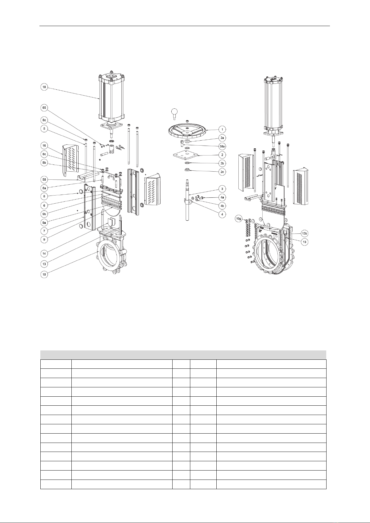
Part list
Pos.
Part
Pos.
Part
1
Hand wheel
8b
Washer
2
Yoke
8c
Nut
2a
Bearing
9
Box packing
2b
Slide washer
9a
Box scraper
2c
Bearing
9b
Box top scraper
3
Stem
10
Valve body
4
Stem nut
10g
Valve body boltings
4a
Washer
13
Seat
4b
Bolt
13b
Pin short
5
Tie rod
14
Guiding pads
6
Gate
16
Gate guards
7
Beam
18
Pneumatic cylinder
8
Gland
58/a
Locking pin
8a
Stud bolt
65
Gate indicator

Document
Document id
Issue
Date
Maintenance instruction
mi-WB14E-HW-SC-EN
1
2021-04-14
4 (10)
3. Disassembling of valve parts
•Steps and procedures described in this section are based on a valve which is not installed in a
pipe system.
•Before any maintenance begins the valve must be removed from the pipe system and the
pneumatic cylinder must be disconnected from the air supply. Follow procedure described in
installation and service instruction for the knife gate valve and its actuator.
•Maintenance shall be performed by qualified personal. Qualified are those persons who, due to
experience, can judge the risk and execute the work correctly and who are able to detect and to
eliminate possible risks.
To simplify the disassembling of the knife gate valve:
WB14E up to DN 300/12”: Place the valve upright in a screw vice.
WB14E up to DN 350/12” – DN 600/24”: Placed on a horizontal work bench.
1. Open the valve completely.
2. Disconnect the air/hydraulic supply or power.
3. If the valve is placed horizontally on a work bench. Make sure to support the gate to ensure its
position remain during the full disassembly.
4. Disassemble the actuator and top works
5. Disassemble the gland (8).
6. Up to DN 300/12”:
a. Remove stuffing box braids and its scrapers (9, 9a, 9b).
b. Remove the gate and internal guiding pads. Go to point 8.
7. DN 350/14” up to DN 600/24”:
a. Unscrew valve body boltings and remove one valve body side from the other.
b. Remove stuffing box braids and its scrapers (9, 9a, 9b).
c. Remove the gate (6) and internal guiding pads (14).
d. Inspect the gate for any damages. Dents and scratches will affect its ability to seal tight.
e. Remove the seat and its locking pins.
8. Clean the inside of knife gate valve carefully.
The box packing, guiding pads and seat are wear parts we recommend always to change at
maintenance.
4. Changing box packing, guiding pads, seat and gate
•Steps and procedures described in this section are based on a valve which is not installed in
a pipe system.
•Before any maintenance begins the valve must be removed from the pipe system and the
pneumatic cylinder must be disconnected from the air supply. Follow procedure described
in installation and service instruction for the knife gate valve and its actuator.
•Maintenance shall be performed by qualified personal. Qualified are those persons who,
due to experience, can judge the risk and execute the work correctly and who are able to
detect and to eliminate possible risks.
Always have the knife gate valve’s article and serial number available to ensure you order
correct spare parts to your valve.
Document
Document id
Issue
Date
Maintenance instruction
mi-WB14E-HW-SC-EN
1
2021-04-14
5 (10)
Before assembling make sure you have:
1. Seat (13)
2. Two short pins if the valve is DN 350/14” or larger (13b).
3. TwinPack box packing braids in correct dimension and length (9).
4. Box bottom scraper/s (9a) and optional top scraper/s (9b).
5. Guiding pads (14).
6. Locking nuts (8c) and washers (8b). Stud bolts (8a) if necessary.
Additional equipment
•Synthetic lubricator (Multipurpose Grease OKS 1110 or similar grease approved for EPDM, Nitril and
FEPM)
•A plastic surfaced hammer and/or a pneumatic cylinder to push down the gate in closed position.
•Necessary lifting equipment for valves > DN 350/14”.
•Adhesive paste type Terason or equal and clamps to valves > DN 350/14”.
Before assembling starts, check the valve body (10) and gate (6) don’t have any damages such
as dents and scrapes. If the gate is damaged it can wear out the box packing (9) and seat (13)
very fast resulting in leakage. To ensure optimal operation, Stafsjö recommends changing the
gate if it is damaged and invest in a new knife gate valve if the body is damaged.
Up to DN 300/12”, follow steps below to change box packing, scrapers, seat and guiding pads.
1. Make sure that the valve body gate groove is clean and free from grease and residues.
2. Put the valve in a vertically up-right position in a screw vise.
3. Mount the seat (13) by pressing it all the way down into the bottom of the valve body until the seat is
even with the valve bore. It is important that the seat is symmetrical mounted and sticks out equally at
both sides on top of the valve body.
4. Apply grease (Multipurpose Grease OKS 1110 or similar grease approved for EPDM, Nitril and FEPM) on
the gate edges to decrease friction against the seat.
5. Push down the gate (6) to the bottom (100 % closed position) of the valve body (10) by using your own
weight or use a plastic hammer.
6. Control the gate (6) is centered in the valve body (10).
7. Install guiding pads (14) in the slots in between the gate and valve body. Ensure you install the guiding
pads correctly
a. Radius should be downwards against the bore side.
b. Bevel edge should face the valve body, not the gate side.
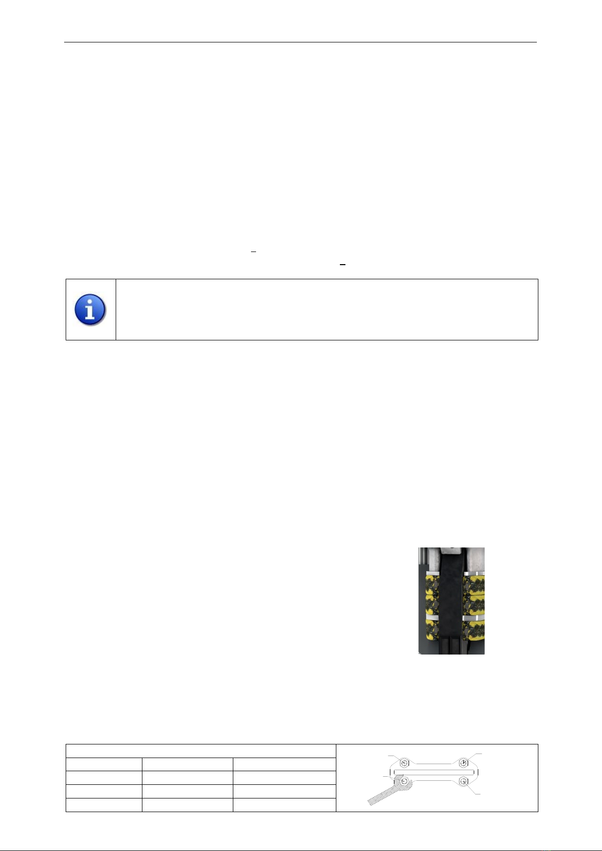
8. Install the first layer of TwinPack box packing braids (9) on each side of the
gate. Make sure they close tightly against the seat. NOTE! Do not use any
sharp tools when installing the box packing braids. It can damage the box
packing and the gate!
9. Add box bottom scrapers (9a) on top of the first layer of braids on each
side of the gate. Box bottom scrapers are a bit thicker than optional top
scrapers. Ensure you install correct ones.
10. Add another two layers of braids (9) on each side of the gate on top the scrapers (9a).
11. Optional top scrapers (9b) can be added on top of the final third layers of braids.
12. Install the gland (8) and tighten it with washers (8b) and locking nuts (8c) gradually and crosswise
according torques submitted in table below. Make sure that the gland is centered in the box and has an
equal distance from the gate all around. Ensure there is no metal contact in between gate and gland.
Recommended maximum torque for gland nuts
DN
Nm
lbf x ft
50-80
20
15
100-150
25
18
200-300
30
22
Box packing
Optional top scraper
TwinPack braids
TwinPack braids
Bottom scrapers
TwinPack braids
3
1
2
4
Document
Document id
Issue
Date
Maintenance instruction
mi-WB14E-HW-SC-EN
1
2021-04-14
6 (10)
If the gland nuts are tightened to hard, it shortens the lifetime of the box packing and the force
needed to operate the valve will increase.
The box packing may start to leak when the system is pressurized and the temperature
increases. This is caused by the box packing which is a soft material that moves depending on
pressure and temperature and when the valve is operated. If the box packing leaks, re-tighten
the gland nuts (8c) gradually and crosswise according torque above.
From DN 350/14”, follow steps below to change box packing, scrapers, seat and guiding pads.
1. Place both valve body halves on a bench and check that the inside is clean. Put some spacers between
the halves, conveniently a thinner piece under the top and a thicker in the bottom. It should be possible
to get in the screws from below!
2. Make sure that the valve body gate groove is cleaned and free from grease
and residues.
3. Apply approx. 3 mm wide Terason adhesive paste in the seat groove in the
gland box and apply it approx. 50 mm below the gland box.
4. Take the seat (13) with the short pins installed (13b) in each end of the seat
and install it into the seat (13) groove in the valve body. Use clamps to hold
it in place. The seat should extend approximately 2 mm in the bottom of
the gland box (the braid will compress it). Make sure that steel pins are
inserted in the housing.
5. Install new guiding pads (14) in the guiding pads groove in the valve body.
6. Apply approx. 3 mm wide Terason adhesive paste in the seat groove in the
gland box and apply it approx. 50 mm below the gland box on the other valve body side.
7. Put the other valve body half in place on top of the one with the seat installed.
a. Make sure that the seat profile pins are inserted correctly in each valve body halves.
b. Insert three body bolts, two in the top and one in the bottom, tighten them gently by hand.
c. Check that the seal profile is positioned correctly.
d. Tighten the body bolts again and then insert the rest of the body bolts.
e. Tighten them but let it be approximately 0,5-1 mm space between the body halves in the lower
area. In the top, tighten the longer bolts according to torque chart below. Tighten remaining
valve body bolting after the actuator have been installed.
8. Apply grease (Multipurpose Grease OKS 1110 or similar grease approved for EPDM, Nitril and FEPM) on
the gate edges.
9. Push down the gate (6) to the bottom (100 % closed position) of the valve body (10) by using your own
weight or use a plastic surfaced hammer. If you have not tightened the valve body bolts all-around it
becomes easier. However due to the friction you may need to use a pneumatic cylinder, to get the gate
down into 100 % closed position. Ensure the gate is cantered and the seat is still in correct position in
the gland box.
10. Install the first layer of TwinPack box packing braid (9). Make sure they close tightly against the seat.
NOTE! Do not use any sharp tools when installing the box packing braids. It can damage the box packing
and the gate!
11. Add box bottom scraper (9a) on top of the first layer of braids. Box bottom scrapers are a bit thicker
than optional top scrapers. Ensure you install correct ones.
12. Add another layer of TwinPack braid (9) on top the scrapers. Make sure the braid ends does not meet on
the same side as the first layer.
13. Add final layer of TwinPack braids. Make sure the braid ends does not meet on the same side as the
second layer.
Screw joints Sd mm
Max recommended torque
Nm for stainless steel A2/A4
Max recommended lbf x ft
stainless steel A2/A4
M12
100/100
74/74
M16
140/190
103/140
M20
275/365
203/269

Document
Document id
Issue
Date
Maintenance instruction
mi-WB14E-HW-SC-EN
1
2021-04-14
7 (10)
14. Optional top scraper (9b) can be added on top of the final third layers of braids.
15. Install the gland (8) and tighten it with washers (8b) and locking nuts (8c) gradually and crosswise
according torques submitted in table below. Make sure that the gland is cantered in the box and has an
equal distance from the gate all around. Ensure there is no metal contact in between gate and gland.
If the gland nuts are tightened to hard, it shortens the lifetime of the box packing and the force
needed to operate the valve will increase.
The box packing may start to leak when the system is pressurized and the temperature
increases. This is caused by the box packing which is a soft material that moves depending on
pressure and temperature and when the valve is operated. If the box packing leaks, re-tighten
the gland nuts (8c) gradually and crosswise according torque chart above.
5. Installation of hand wheel kit
1. Assemble the stem nut (4) on the gate with screws (4a) and washers (4b). Note! Do not tighten fully to
finally adjust it when the yoke (2) has been assembled.
2. Lubricate the thread on the stem (3) with grease (Q8 Ruysdael or equal). Assemble and screw the stem
(3) into the stem nut (4).
3. Install bearing (2c) on the stem with narrow side facing the yoke.
4. Install slider washer (2b) on top of the bearing (2c).
5. Place the yoke (2) on the beams. Check that the lower bushing fit into the hole of the yoke plate. The
slide washer shall be in line with the yoke.
6. Install upper slide washer (2b) and bushing (2a).
7. Hold the beams (9) together by hand and tighten the nuts (8c) with washers below (8b) on the yoke (2)
crosswise incrementally.
8. Tighten up the screws in the stem nut.
9. Assemble the hand wheel with washer and locking nut.
10. Make sure bearings (red) and slide washers (yellow)
(2a, 2b, 2c) are inserted and tightly compressed against
the yoke. If there is any play in between the yoke and
bearings and its slide washers, eliminate it by rotating
the stem counter clockwise.
11. Complete the installation by tighten up the locking nut
on top of the hand wheel.
12. Make a full on/off operation test for verification.
Recommended maximum torque for gland nuts
DN
Nm
lbf x ft
350-600
35
26
3
1
2
4
Document
Document id
Issue
Date
Maintenance instruction
mi-WB14E-HW-SC-EN
1
2021-04-14
8 (10)
6. Changing from hand wheel to SC double-acting pneumatic cylinder when the
valve is installed between flanges
6.1 Safety warnings
•This instruction includes safety instructions for foreseeable risks during assembly of the
cylinder onto a Stafsjö WB14E knife gate valve. It is the users responsibility to minimize
or eliminate the potential for harm or injury that could be present in the overall
system, or surrounding environment.
•Valve and actuator installation and service instructions also has to be respected and
followed.
•Any assembly and disassembly work must be completed by qualified personnel only.
Qualified personnel are persons who, on the basis of their training, specialist
knowledge and professional experience, can correctly assess and execute the work
assigned to them and can identify and avoid potential risks.
•The same requirements for the compressed air supply system and the local plant
control system are to be complied with for the cylinder. These requirements must be
additionally complied with when connecting the cylinder.
•No exterior loads must be applied to the cylinder. If it needs to be supported, section
3.4 need to be observed.
•The cylinder and accessories must be protected from such ambient influences that can
pose a functional risk.
•Make sure that access to the installation site, as well as the installation site itself, is
easily accessible and provides sufficient space, lightning, visibility for installation.
•After assembling the actuator should be freely accessible.
•If a fault or problem is detected, the knife gate valve must be disconnected and
maintained.
•After installation, the function of the valve and actuator must be in accordance with
the valve and the actuator destinations. See installation and service instructions for
further information.
Danger
No work is allowed on the knife gate valve when the system is pressurized. The system must be
free from pressure and empty.
Work on the knife gate valve when the system is under pressure can cause serious harm to
persons and damages to equipment.
Danger
•During installation, the actuator must be secured against falling at all times and
disconnected from the air supply.
•To do this make sure that exclusively validated and approved hoists are used. The assembly
may only be completed by qualified personnel. Avoid a physical overload.
6.2 Conditions for the combination of valve and pneumatic cylinder
•The cylinder Ø and the stroke must be in accordance with the valve type and its size.
•The cylinder has an adapter (38) assembled and match the interface of the valve.
•The valve has beams (7) with holes for limit switches in opened/closed position and lockout if needed.
•The clevis pin (20) and the split pins (21) match.
•The clevis pin (20) match the hole in the gate.
•The two gate guards cover the stroke of the gate (16).
•The quality of the compressed air corresponds to the specifications in the actuator installation and
service instruction and the compressed air connections comply with the specifications.
•Ensure the feed line for the compressed air is adequately dimensioned.
Document
Document id
Issue
Date
Maintenance instruction
mi-WB14E-HW-SC-EN
1
2021-04-14
9 (10)
As standard Stafsjö supply SC double-acting cylinder conversion kits customized for each valve
type and size. To ensure correct conversion kits are supplied, the purchaser must supply all
required information with the order, i.e. article and serial number of the valve. Using any other
parts than original Stafsjö parts may cause malfunction and is the responsibility of the user.
Danger
For reasons of safety, a valve with pneumatic actuator may only be operated once all gate
guards have been properly assembled on the valve. If this is not observed, life and health of the
personnel are at risk. These gate guards partly prevent the visual check of the valve’s gate
position. If required, two electronic limit switches can be installed onto the valve for indicating
of opened and closed position or a gate indicator pin.
The connection of any additional electric/electro-pneumatic modules supplied with the actuator is described
in the accompanying documentation and must be observed. These documents apply in addition to these
instructions. Installation of accessories not intended for this purpose is not permitted.
6.3 Compressed air connections
The compressed air connections of the pneumatic cylinder have an interface according to <Namur VDI/VDE
3845> and threaded holes according to ISO 228-1:
Cylinder size
Connection
Compressed air supply *)
SC100-SC160
G ¼”
Min. 8 mm
SC200-SC320
G ½”
Min. 15 mm
*) This inner dimension must be larger in case of long air feed lines
Suitable seals are to be used for the screw connections in the cylinder. The pipework for the compressed air
supply to the cylinder should be at least the same size as the air connections. If the feed line is undersized,
this can result in a malfunction.
6.3 Converting an installed hand wheel operated WB14E to SC double-acting
pneumatically operated
Danger
No work is allowed on the knife gate valve when the system is pressurized. The system must be
free from pressure and empty.
Work on the knife gate valve when the system is under pressure can cause serious harm to
persons and damages to equipment.
Assemble in the following steps:
1Make sure that the valve is closed.
2Dissemble the hand wheel kit (1, 2a, 58a, 2, 2b, 2c, 3, 4, 4a, 4b).
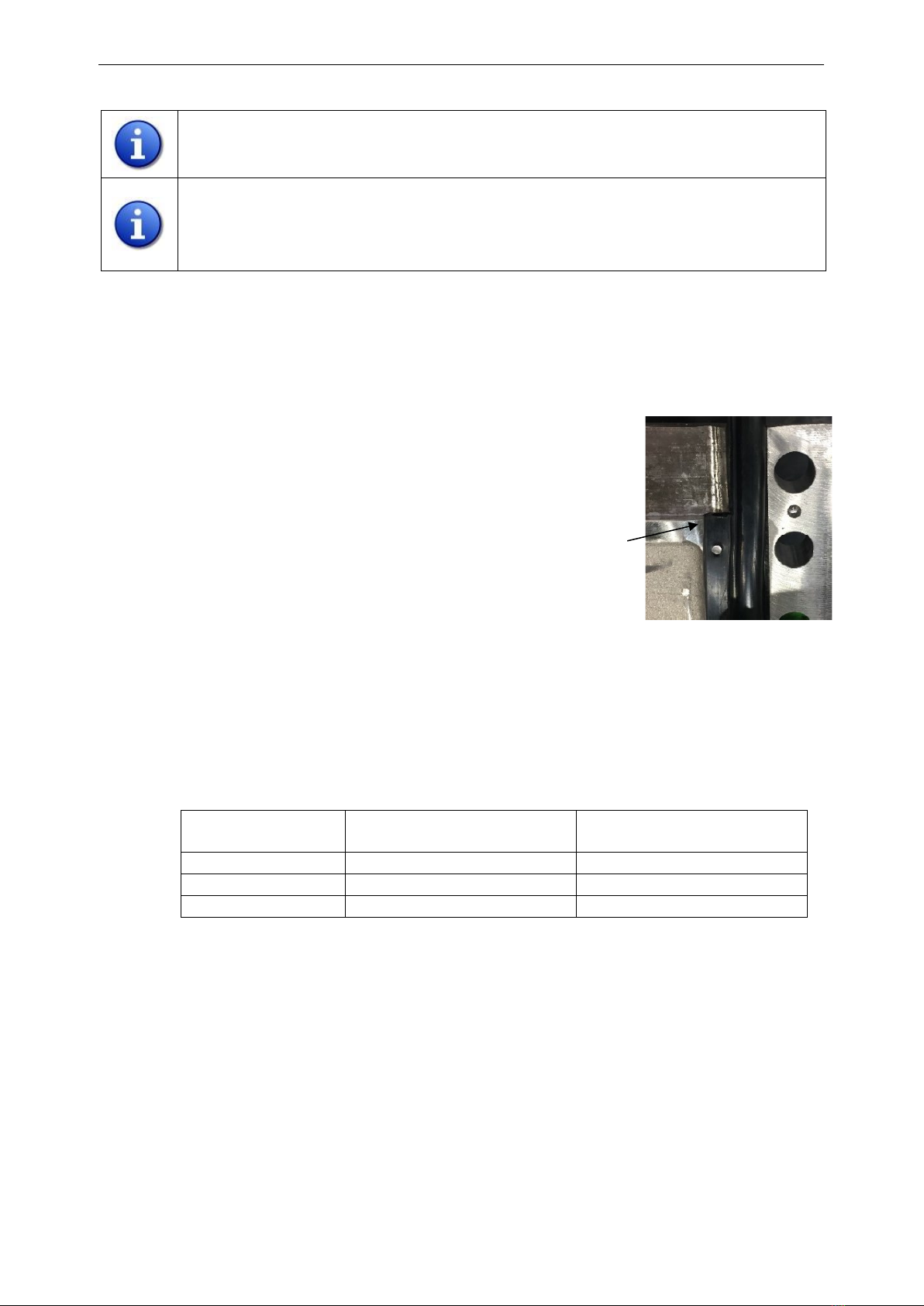
3If the valve has beams (7) with limit switch and lockout holes, continue
to step 5. If the valve does not have it, these must be replaced with new
beams with holes.
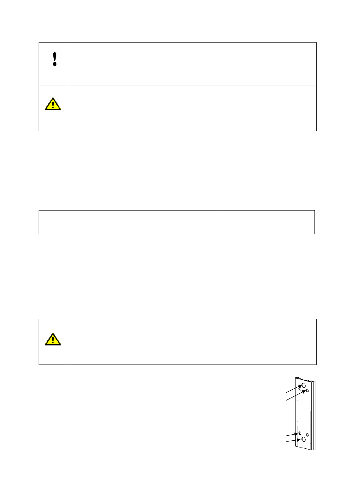
4Lift of the beams (7) and replace with new beams with lockout and limit
switch holes. The holes on the beam are placed on different distances
from the short side of the beam. The side of the beam with the longest distance between the hole
and the short side shall be placed against the top of the valve body.
5Ensure the tie rods (5) are properly tightened into the valve body. Re-tighten if necessary.
Limit swith holes
Lockout holes
Lockout holes
Limit swith holes
Document
Document id
Issue
Date
Maintenance instruction
mi-WB14E-HW-SC-EN
1
2021-04-14
10 (10)
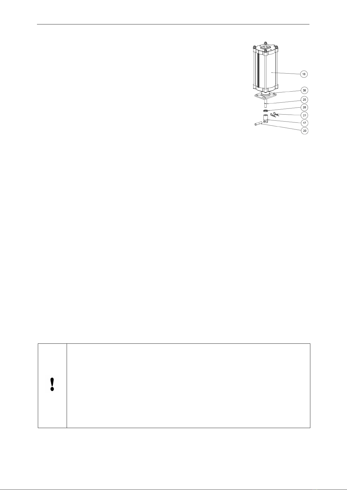
6Assemble the locking nut (28) onto the threaded piston rod (25). Do not
tighten the locking nut fully if stroke length has to be adjusted.
7Assemble the gate clevis (17) on the threaded piston rod (25).
8Assemble the cylinder (18) onto the beams (7) and tie rods (5).
9Center the cylinder (18) and press the beams (7) together and tighten the
tie rod nuts (8c) manually, evenly and crosswise all-around. Use washers
below the nut. Do not tighten fully!
10 Connect the air supply to the cylinder and move the piston rod (25) towards
the gate (6) by gently operating the cylinder. Make sure that the hole in the
gate clevis (17) will interface with the hole in the gate and with the hole in
the beams (7) to enable installation of the clevis pin (20).
11 Connect the clevis (17) with the gate (6) using the clevis pin (20) and secure it with the split pins
(21).
12 Finnish tightening of the tie rod nuts on the valve-cylinder interface evenly and crosswise while
holding the beams together.
13 Open the valve completely by gently operating the pneumatic cylinder (18). In full open position the
clevis pin should be in the center of upper limit switch hole. If the valve has lockouts in open/closed
position, ensure beam lockout holes and gate lockout holes are also aligned. If all are aligned and
centered, continue to step 15.
14 If the clevis pin or the gate lockout holes are not centered in the upper beam holes, measure
distance to have them centered. Demount the split pins (21) and clevis pin (20), then gently open
the cylinder far enough to adjust locking nut and gate clevis. Disconnect the air supply. Adjust the
gate clevis (17) and locking nut (28) to correct position. Ensure you are not turning the piston rod,
only gate clevis and locking nut. Re-do step 10-11 and 13.
15 Lock the gate clevis (17) with the locking nut (28). For extra reliable locking, apply Loxeal thread
adhesive type 55-03 or similar on the gate clevis top before tightening the locking nut.
16 Install gate indicator (65) if needed and gate guards (16) and the black protective caps (7a) in the
beam holes if not limit switches are used.
17 Make a full function test of the knife gate valve.
18 Ensure installation and service instruction for valve, actuator and accessories are followed and the
unit have passed all tests.
19 Operate the valve a few times before the system is pressurized. Leave the valve in desired (open or
closed) position.
•A valve with double-acting pneumatic cylinder requires a continuous supply of
compressed air to ensure reliable and steady operation.
•The cylinder should be regularly checked visually for tightness or damage to ensure
that the external conditions do not poses any risk for the operating personnel, cylinder,
valve or its accessories.
•Inspect the valves on regular basis for any leakages. Seat and box packing are wear
parts that have to be replaced regularly. The interval for both inspection and
replacement depends on the application and operating data such as pressure,
temperature, erosion, chemical, mechanical effect of the media on the materials in the
knife gate valve and on how often the valve is operated.
Table of contents
Popular Industrial Equipment manuals by other brands


CBS ArcSafe
CBS ArcSafe RSA-174F Installation and operation

Balluff
Balluff BTL PF 400 Series user guide

Beko
Beko DRYPOINT M DM 08-14 R Instructions for installation and operation

Siemens
Siemens 3NP1144 Series operating instructions

Interactive Instruments
Interactive Instruments Jet Stream 500 instruction manual

Youngman Richardson & Co
Youngman Richardson & Co JIBBI 1250-EVO user manual