CF-9 User's Guide
09/30/92 GPD Global 1
Introduction
This document is intended for use by those who install, operate and maintain GPD's CF-9 Radial
Lead Forming Machine (GPD Part# CF9.BASE.120 or CF9.BASE.230).
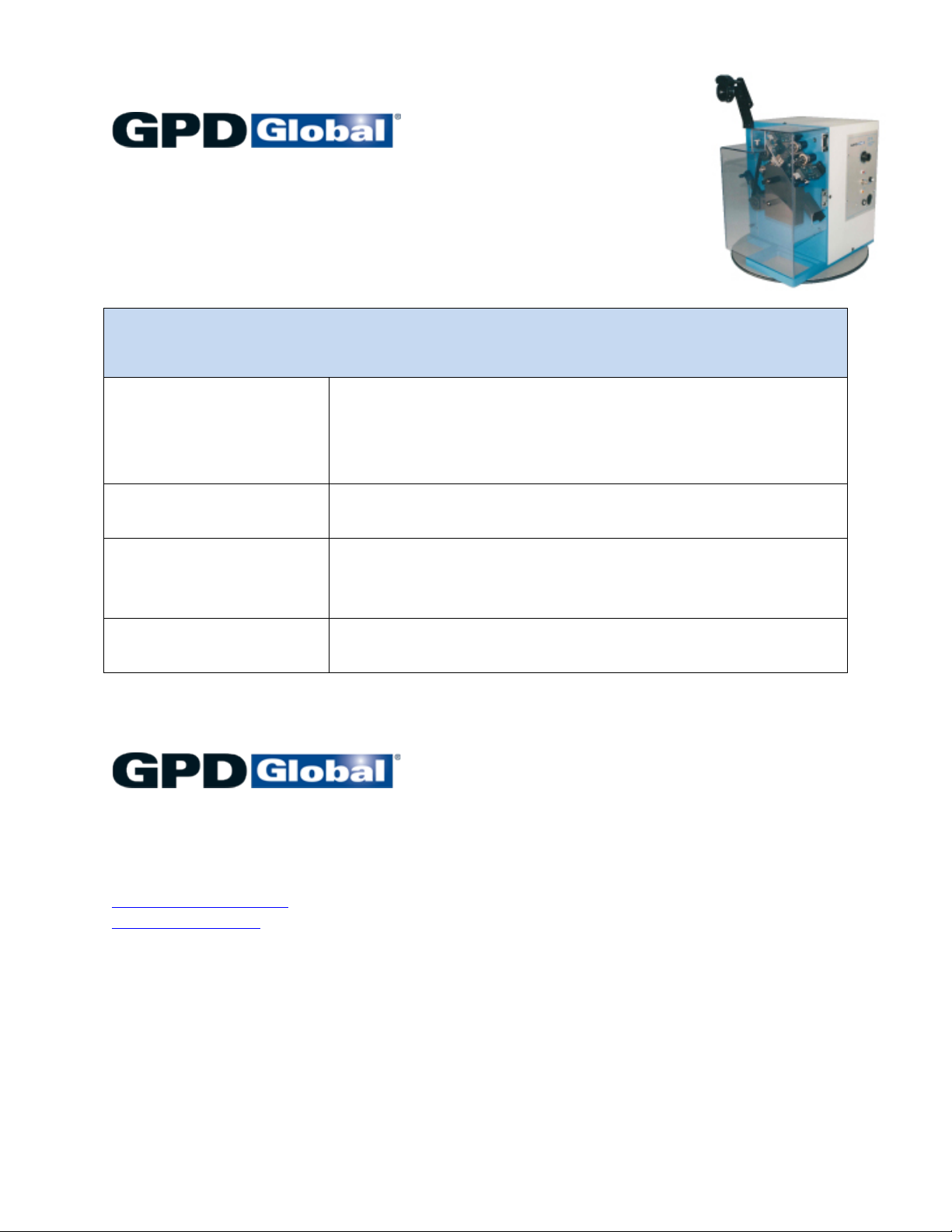
CF-9 Radial Lead Forming Machine
GPD's self-contained CF-9 Radial Lead Forming Machine has become the industry standard for
versatility, accuracy, repeatability, and ease of setup and change over. The CF-9 forms and cuts
to length a wide variety of two- and three-leaded taped radial components such as TO-92's,
capacitors, transistors, and LED's. It processes both standard and special forms precisely and
repeatedly.
Two die stations with standard micrometer scale indicators adjust independently. Performing
adjustments with the micrometer scales enables quick setup of proper forming and/or cutting
settings.
As the first component moves through the system, it is presented to two die stations. The first
die station is generally used to form components, and the second to cut components from the
tape. Depending on the components being processed and the desired component lead form,
the second station may be used to both cut and form, just cut, or be excluded in order to leave
components on tape.
The indexing system, the heart of the CF-9, drives the studded transfer belt. The studs, or pins,
on the belt pick up the tape holes and index exactly 1/2" (12.70 mm) every time.
The CF-9 is ruggedly constructed of heavy duty parts and sealed ball bearing shaft assemblies
for low maintenance. All of the machine's parts are precisely made and treated to prevent
corrosion, enhance appearance, or facilitate proper function.
The tape roller guide includes studded protrusions to hold the component tape solidly in place —
the tape cannot run off the drive belt mechanism. Waste tape feeds down a tape exit chute and
out to the side of the machine for easy disposal.
The CF-9's capabilities expand with its Loose/Bulk Component Feeder and Automatic Taped
Component Re-reeler accessories by combining the functions of several machines into one.
Additional accessories such as the Electronic Component Counter, Component Detection
System, Lazy Susan, Work Station, and Footswitch are also available to help increase your
production and profit.