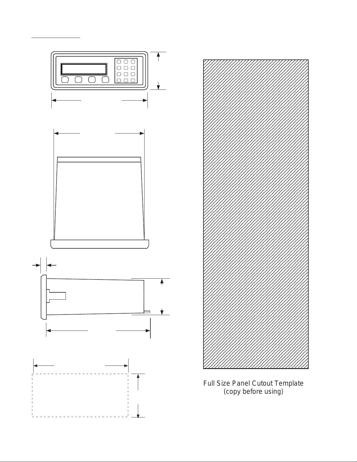
GPI GBT 110 User manual

99878 05/20/03
Description
The Batcher is a programmable, microprocessor based unit which provides batch control, monitors flow
rate and controls the flow of processing liquids. Start/Stop controls can be used in conjunction with
prewarn and final relays to provide valve actuation or pump control. An optional configuration offers
streamlined preset adjustments, remote Start, Stop & Reset, and weighted averaging.
Application
The unit is normally used for batch control or inventory tracking. The display may be toggled between
batch, rate, and grand total. A programmable K-factor makes keying-in engineering units easy. The unit
accepts pulse or contact closure inputs and provides two separate preset controls.
GBT
Principle of Operation
The batcher receives an input from a pulse producing flowmeter through a sensor. The user programs
the batcher to condition the incoming pulses signal and compute the batch flow and flow rate. A wide
variety of different functions can then be performed based on the programmed configurations such as
start/stop functions, totalizing, and/or flow rate monitoring.
GBT Series Technical Manual
GBTGBT
GBTGBT
GBT
Installation and Operating Manual
Features
❑Start/Stop Buttons & Remote Inputs
❑Separate 8 Digit K-Factors For Rate & Total
❑Accepts Pulse Inputs
❑Displays Rate, Total and Grand Total
❑Security Lockout with Missing Pulse Detection
❑Scaled Pulse Output
❑2 Setpoints For Two Stage Valve Control
❑NEMA 4X (IP65) Front Panel

!
SAFETY INSTRUCTIONS
The following instructions must be observed.
• This instrument was designed and is checked in accordance with
regulations in force EN 60950 (“Safety of information technology
equipment, including electrical business equipment”).
A hazardous situation may occur if this instrument is not used for its
intended purpose or is used incorrectly. Please note operating
instructions provided in this manual.
•The instrument must be installed, operated and maintained by
personnel who have been properly trained. Personnel must read and
understand this manual prior to installation and operation of the
instrument.
•The manufacturer assumes no liability for damage caused by incorrect
use of the instrument or for modifications or changes made to the
instrument.
Technical Improvements
•The manufacturer reserves the right to modify technical data without
prior notice.

1. INTRODUCTION
1-1 General Description ................................................................................................ 1
1-2 Typical Application................................................................................................... 1
1-3 Principles of Operation............................................................................................ 1
1-4 STD PRE and EZ PRE Operation Modes ............................................................... 3
1-5 Specifications .......................................................................................................... 4
1-6 Dimensions ............................................................................................................. 5
2. INSTALLATION
2-1 Receipt of Equipment.............................................................................................. 6
2-2 Return Shipment ..................................................................................................... 6
2-3 Panel Mounting ....................................................................................................... 6
2-4 Electrical Connections............................................................................................. 6
2-5 Wiring Connections and Diagrams.......................................................................... 7
3. OPERATION
3-1 Front Panel Operation............................................................................................. 8
3-2 Programming........................................................................................................... 9
3-3 K-Factor Programming............................................................................................ 9
3-4 Programming Flow Chart ...................................................................................... 10
3-5 How to Program .....................................................................................................11
3-6 Frequently Asked Questions About Setting Up The Batcher..................................11
3-7 Setup Procedure For The Batcher ........................................................................ 12
3-8 Run Mode.............................................................................................................. 20
3-9 Internal Operation ................................................................................................. 21
4. INPUTS
4-1 Digital Pulse Inputs ............................................................................................... 22
4-2 DC Power Inputs ................................................................................................... 24
4-3 AC Power Inputs ................................................................................................... 24
CONTENTS

5. OUTPUTS
5-1 Frequency Output ................................................................................................. 24
5-2 Control Outputs ..................................................................................................... 25
6. TROUBLE SHOOTING AND MAINTENANCE GUIDE
6-1 Warning Messages................................................................................................ 26
6-2 Troubleshooting..................................................................................................... 27
6-3 Removing The Case ............................................................................................. 28
6-4 Maintenance.......................................................................................................... 28
7. CALCULATING THE K FACTORS
7-1 General ................................................................................................................. 28
7-2 Calculating the K Factors ...................................................................................... 29
8. Programming Worksheet ................................................................................................ 30
CONTENTS

1
SECTION 1 INTRODUCTION
1-1 General Description
Featuring8digitsofbright,.55inch,alphanumeric
display,theGBTcanacceptupto20,000pulses
per second of digital count. The user, with the
push of a button, can toggle the display to view
thetotalofthebatch,therateoffloworthegrand
total of flow.
The GBT may be thought of as two separate
countersandaratemeter. The"batching"counter
counts to prewarn and preset numbers entered
bytheuserandenablesseparatecontroloutputs.
The "totalizing" counter gives a cumulative
readingorgrandtotal.Theratemeterscalesthe
inputpulsestoprovidegallonsperminuteorany
other rate measurement without the totalizer
losing counts.
Setup is done through the front panel and the
menu driven software in the unit. Start-Stop
control can be activated via the front panel
buttons or remote inputs.
The unit uses an EEPROM to hold data a
minimum of 10 years if power is interrupted.
1-2 Typical Application
The above application involves liquid flow.
The start button is pushed and the Batcher
receives pulses from the flowmeter. The
pulses are scaled by the K Factor and sent
out via the pulsed output to an external
counter. As the Prewarn is reached, the
control valve partially closes. When the final
Preset is reached the valve shuts down com-
pletely. At any time the flow can be sus-
pended by hitting the stop button.
1-3 Principles of Operation
Presets
When the start button is pushed, two relays
engage simultaneously to start flow. When
the prewarn number is reached, one relay
drops out. When the preset number is
reached, the other relay drops out. The user
may enter the two numbers when setting up
the batch counter. The prewarn is set a cer-
tain number of counts less than the preset
number. If the prewarn is set larger than the
preset, the message "PREWRONG" will ap-
pear on the display.
Ratemeter
Accurate to 5 1/2 digits (±1 display digit). The
ratemeter can be programmed to accept al-
most any number of pulses per unit of mea-
surement, sample from 2 to 24 seconds maxi-
mum, and auto range up to 6 digits of signifi-
cant information. The ratemeter with a K Fac-
tor of 1 displays the rate of pulses per second.
Simply dial in the proper K Factor to display in
minutes, hours or other units of measurement.
Press the C button, while the unit is displaying
the batch, to display the rate; 'R' is displayed
on the left side of the display.
K Factor
The K Factor is used to convert the input
pulses or analog input into workable units.
The 8 digit K Factor is a divider with a range
of 0.00011 to 99999999 (the decimal point
may be keyed into any position). Separate K
Factors may be entered into the count and
rate sections of the Batcher. Thus, you may
batch in gallons and display rate in liters per
hour. The maximum factored count speed is
20000 Hz. The maximum factored rate is 7
digits.
123456
Flowmeter
Computer
Solenoid Valve
Remote
Totalizer
Strip Chart
Recorder
Pulse Output
RS232
Output
Analog
Output

2
1-3 Principles of Operation (continued)
Counter
The maximum count is 99999999. In the
setup mode choose "RO" (Reset to Zero) for
adding (count up) operation or "SP" (Set to
Preset) for subtracting (count down) opera-
tion. At any time, the display can be made
to flash the Grand Total by pressing the ENT
button while in the run mode. Activating the
CLR button while the Grand Total is flashing,
resets the Grand Total counter.
Lockout
Unauthorized front panel changes can be pre-
vented by entering a user selected, four digit
code, in the "Lockout" mode. The status of
the unit can be observed but "LOCK ON" ap-
pears if changes are attempted. Entering the
code again returns the unit to "LOCK OFF"
status.
Frequency out
The Batcher generates a pulse out for each
factored count. An NPN transistor output (Pin
2), can drive external devices at rates of 10,
200, 2000 or 20000 counts per second as se-
lected through the keypad menu. If the K
Factor scaled inputs generate pulses faster
than the output speed selected, an internal
buffer will store up to 9,999 counts before
"DATALOST" flashes on the screen. This in-
dicates that the counts being totaled and the
scaled outputs may be incorrect. Note that
all counts stored in the internal buffer will be
pulsed out at the selected frequency even if
the counter is reset.

3
STD PRE and EZ PRE Operation Modes
The batcher software allows the user to choose between STD PRE (Standard Preset) and EZ PRE
(Easy Preset) operation modes. STD PRE operation is well suited for batch amounts that do not
change, since the program mode must be entered to change the preset and the batch count must
be cleared before starting a new batch. EZ PRE has been designed for users who frequently
change the batch amount. During EZ PRE operation, the preset can be viewed and changed
without entering the program mode and another batch can be started without resetting the unit.
Note:
Before a batch is started and after a batch is complete, the unit will continue to totalize all
inputs.
Using STD PRE
Programming
Select STD PRE - Go into the Program Mode and
select STD PRE in the PRE TYP sub menu.
Set the PRESET and PREWARN - Go into the
Program Mode and enter the desired values for
the PRESET and the PREWARN.
Program the Counter - Go into the Program
Mode and set up the counter in the COUNT sub
menu.
Operation
Start a Batch - In the Run Mode, reset the total
by pressing “CLR”, then press “A” to start.
When started, both relays energize and the
counter begins to count. When the batch is
complete, the relays drop out and the unit
displays the amount that was batched (0 if in
Set to Preset mode).
Stop a Batch - Press “B”, to temporarily stop
process by de-energizing the PRESET and
PREWARN relays. Press start, “A”, to continue
process.
Repeat a Batch - In the Run Mode, reset the total
and press the start button.
Change the Batch Size - Go to the Program
Mode and enter new PRESET and PREWARN
values.
Using EZ PRE
Programming
Select EZ PRE - Go into the Program Mode and
select EZ PRE in the PRE TYP sub menu.
Set the PRESET and PREWARN - Go into the
Program Mode and enter the desired values
for the PRESET and the PREWARN.
Program the Counter - Go into the Program
Mode and set up the counter in the COUNT
sub menu.
Operation
Start a Batch - In the Run Mode, press “A” to
start. When started, both relays energize and
the counter begins to total. When complete,
the relays drop out and the display flashes the
current PRESET value.
Stop a Batch - Press “B”, to temporarily stop
process by de-energizing the PRESET and
PREWARN relays. Press start, “A”, to continue
process.
Repeat a Batch - Press the start button.
Change the Batch Size - With the current
PRESET flashing on the display, type a new
number using the keypad. This number
becomes the PRESET.
Display Batch Total or Rate - With the current
PRESET flashing, press “ENT” to place the
PRESET value in memory and use the “C”
button to toggle between the Batch Total and
the Rate.
1-4 STD PRE and EZ PRE Operation Modes

4
1-5 Specifications
Housing:
High impact plastic case with NEMA 4X front
panel.
Dimensions:
See Section 1-5, Page 4.
Display:
8 Digit, 0.55" High, 15 Segment, Red Orange,
LED.
Input Power:
A: 110 VAC ±15% or 12 to 27 VDC
B: 220 VAC ±15% or 12 to 27 VDC
NOTE: AC Inputs are internally fused with a
160mA slow blow fuse.
Current:
Maximum 280 mA DC or 5.3 VA at rated AC
voltage.
Output Power:
(On AC powered units only): +12 VDC at 100
mA. Separate Isolated 12 VDC at 100 mA to
allow ±12 VDC or +24 VDC, regulated ±5%
worst case.
Temperature:
Operating: +32°F (0°C) to +130 °F (+54°C)
Storage: -40°F (-40°C) to +200 °F (+93°C)
(Extended operating temperature range
available, consult factory)
Memory:
EEPROM stores all program, display mode
and count data for a minimum of 10 years if
power is lost.
Reset
Front push button: "CLR" resets displayed
number and control output.
Remote Input (Terminal 5): Open or 0 to 1
VDC (low), 3 to 30 VDC (high), 10K ohm input
impedance to ground. Minimum pulse on /
off time 5 msec.
Accuracy over full temperature range:
Digital - 100% (within specified voltage
ranges)
Pulse Inputs:
Standard, High impedance pulse input.
Low: Open or 0 to 1 VDC
High: 3 to 30 VDC, 10K Ohm impedance
Count Speed (Switch selectable):
100 Hz, 1000Hz, 20000Hz
Termination Resistance (Switch selectable):
10K pull down, 4.7K pull up
Factored Output:
One pulse per each factored count
Sinking (NPN Transistor)
OpenCollectorsinks250mAmaximum to1volt
maximum from 30 VDC maximum
Internal buffer: 9999 pulses
Output speed: user selectable (see table
below)
Speed (Hz) 10 200 2000 20000
Min. on/off (msec) 47.5 2.0 0.2 0.013
Control Outputs:
SPDT Relays
Contact rating: 10 A 120/240 VAC or 28
VDC.

5
1-6 Dimensions
PANEL
CUTOUT 2.50 -0, +0.02
(63.5 -0, +0.5)
7.375 -0, +0.04
(187.3 -0, +1)
7.375
(187.3)
(NOM.)
0.53
(13.5)
6.0
(152.4)
2.48
(63)
(NOM.)
(NOM.)
ABCD
1 2 3
4 5 6
7 8 9
CLR
0
SET
8.17
(207.5)
3.31
(84)
12345678901234567890123456789012123
1
234567890123456789012345678901212
3
1
234567890123456789012345678901212
3
1
234567890123456789012345678901212
3
1
234567890123456789012345678901212
3
1
234567890123456789012345678901212
3
1
234567890123456789012345678901212
3
1
234567890123456789012345678901212
3
1
234567890123456789012345678901212
3
1
234567890123456789012345678901212
3
1
234567890123456789012345678901212
3
1
234567890123456789012345678901212
3
1
234567890123456789012345678901212
3
1
234567890123456789012345678901212
3
1
234567890123456789012345678901212
3
1
234567890123456789012345678901212
3
1
234567890123456789012345678901212
3
1
234567890123456789012345678901212
3
1
234567890123456789012345678901212
3
1
234567890123456789012345678901212
3
1
234567890123456789012345678901212
3
1
234567890123456789012345678901212
3
1
234567890123456789012345678901212
3
1
234567890123456789012345678901212
3
1
234567890123456789012345678901212
3
1
234567890123456789012345678901212
3
1
234567890123456789012345678901212
3
1
234567890123456789012345678901212
3
1
234567890123456789012345678901212
3
1
234567890123456789012345678901212
3
1
234567890123456789012345678901212
3
1
234567890123456789012345678901212
3
1
234567890123456789012345678901212
3
1
234567890123456789012345678901212
3
1
234567890123456789012345678901212
3
1
234567890123456789012345678901212
3
1
234567890123456789012345678901212
3
1
234567890123456789012345678901212
3
1
234567890123456789012345678901212
3
1
234567890123456789012345678901212
3
1
234567890123456789012345678901212
3
1
234567890123456789012345678901212
3
1
234567890123456789012345678901212
3
1
234567890123456789012345678901212
3
1
234567890123456789012345678901212
3
1
234567890123456789012345678901212
3
1
234567890123456789012345678901212
3
1
234567890123456789012345678901212
3
1
234567890123456789012345678901212
3
1
234567890123456789012345678901212
3
1
234567890123456789012345678901212
3
1
234567890123456789012345678901212
3
1
234567890123456789012345678901212
3
1
234567890123456789012345678901212
3
1
234567890123456789012345678901212
3
1
234567890123456789012345678901212
3
1
234567890123456789012345678901212
3
1
234567890123456789012345678901212
3
1
234567890123456789012345678901212
3
1
234567890123456789012345678901212
3
1
234567890123456789012345678901212
3
1
234567890123456789012345678901212
3
1
234567890123456789012345678901212
3
1
234567890123456789012345678901212
3
1
234567890123456789012345678901212
3
1
234567890123456789012345678901212
3
1
234567890123456789012345678901212
3
1
234567890123456789012345678901212
3
1
234567890123456789012345678901212
3
1
234567890123456789012345678901212
3
1
234567890123456789012345678901212
3
1
234567890123456789012345678901212
3
1
234567890123456789012345678901212
3
1
234567890123456789012345678901212
3
1
234567890123456789012345678901212
3
1
234567890123456789012345678901212
3
1
234567890123456789012345678901212
3
1
234567890123456789012345678901212
3
1
234567890123456789012345678901212
3
1
234567890123456789012345678901212
3
1
234567890123456789012345678901212
3
1
234567890123456789012345678901212
3
1
234567890123456789012345678901212
3
1
234567890123456789012345678901212
3
1
234567890123456789012345678901212
3
1
234567890123456789012345678901212
3
1
234567890123456789012345678901212
3
1
234567890123456789012345678901212
3
1
234567890123456789012345678901212
3
1
234567890123456789012345678901212
3
1
234567890123456789012345678901212
3
1
234567890123456789012345678901212
3
1
234567890123456789012345678901212
3
1
234567890123456789012345678901212
3
1
234567890123456789012345678901212
3
1
234567890123456789012345678901212
3
1
234567890123456789012345678901212
3
1
234567890123456789012345678901212
3
1
234567890123456789012345678901212
3
1
234567890123456789012345678901212
3
12345678901234567890123456789012123
Full Size Panel Cutout Template
(copy before using)

6
!
SECTION 2 INSTALLATION
2-1 Receipt of Equipment
When the equipment is received, the outside
packing case should be checked for damage
incurredduringshipment. If thepackingcaseis
damaged, thelocalcarrier shouldbenotified at
once regarding his liability. A report should be
submitted to the factory.
Carefully remove the equipment from the pack-
ing case and inspect for damaged or missing
parts.
2-2 Return Shipment
DonotreturnassemblyorpartwithoutaReturn
MaterialAuthorization. TheRMAisobtainedby
calling your local distributor.
2-3 Panel Mounting
The controller should be located in an area with
a clean, dry atmosphere which is relatively free
of shock and vibration. The Batcher is installed
in a 7.365" (187 mm) wide by 2.495" (63.4 mm)
high panel cutout. To mount the controller
proceed as follows:
a. Prepare the panel opening.
b. Slipthegasket(provided)overtherearofthe
counter case and slide it forward until it
engagestheinnersurfaceof thefrontbezel.
c. Installthescrews(provided)inthemounting
brackets and insert in the holes located on
both sides of the Batcher.
d. Tighten the screws firmly to attach the
counter bezel to the panel.
2-4 Electrical Connections (Reference Figures
2-1 to 2-3)
All connections are completed at terminal
blockslocatedattherearofthecase. Makesure
all power is disconnected before making any
electrical connections. In cases where cables
aresituatedinareaswithheavyelectricalfields,
shielding is required for maximum noise im-
munity. One end of the shielding should be
connected to earth ground. Relays or induc-
tive coils connected to or located in the imme-
diate area should be arc suppressed with ap-
propriate diodes, MOV's or resistor capacitor
networks.
Caution: An external fuse is required:
DC Power: 0.5 Amp
AC Power: 0.125 Amp

7
2-5 Wiring Connections and Diagrams
Figure 2-2
Typical Wiring Connections
2-5 Wiring Connections and Diagrams
1 • NOT USED
2 • SCALED OUTPUT (OPEN COLLECTOR)
3 • NOT USED
4 • INPUT (PULSE)
5 • STOP / RESET INPUT
6 • NOT USED
7 • NOT USED
8 • NOT USED
9 • NOT USED
10 • START INPUT
11 • GROUND (-DC)
12 • GROUND (-DC)
13 • 12 VOLTS OUT
14 • + DC POWER IN (12 to 27 VDC)
15 • ISOLATED -12 VOLTS OUT
16 • ISOLATED +12 VOLTS OUT
17 • AC INPUT
18 • AC INPUT
19 • NO CONNECTION
20 • NO CONNECTION
1 • N.O.
2 • N.C. PRESET
3 • COMMON
4 • N.O.
5 • N.C. PREWARN
6 • COMMON
Figure 2-1 Terminal Block Connections
Flowmeter
(DC Pulse Output)
•4 - Input A
.
.
•12 - Ground (-DC)
•13 - 12V Out
•14 - DC Power In
•15 - Isolated -12V
•16 - Isolated +12V
•17 - AC In
•18 - AC In
110 VAC
60/50 Hz
+
-

8
3-1 Front Panel Operation
START - Pressing “A”, starts the process
by energizing the PRESET and
PREWARN relays. Press “CLR” to reset
Batch Total before starting new batch.
STOP - Pressing “B”, will temporarily stop
the process by de-energizing the
PRESET and PREWARN relays. Use
START to continue the process from
where it stopped.
RATE/TOTAL - Pressing “C” toggles
between rate and total count displays.
The rate display has an “R” on the left
side of the screen.
MENU - Pressing “D” takes the unit out of
the Run Mode and into the Programming
Mode. “D” is also used to make some
programming selections.
ENT - With Count showing in the Run
Mode, pressing “ENT” displays the Grand
Total, which begins flashing on the
screen. Press “ENT” again to return to the
Count. In the Programming Mode, “ENT”
is used to accept a selection.
CLR - When the count total is displayed,
pressing “CLR” will reset the counter to 0
or to Preset A depending on how it was
programmed. When the Grand Total is
displayed, pressing “CLR” will reset it to
0. When the Preset or Program Mode
values are displayed, pressing “CLR” will
reset them to 0, so that new values can
be entered.
A
B
C
D
ENT
CLR
Weighted Averaging
The batcher software includes weighted
averaging of the rate display. Weighted averaging
is not available on units with 16 Point
Linearization.
Weighted averaging can be used to create a more
stable display when the rate input is fluctuating. A
weight, “W”, from 00 to 99 is applied to the old
rate data before the new rate data is sent to the
display. The following equation is used:
W = Weight (00-99)
If a weight of 00 is used, the new rate data will go
directly to the display without being averaged. If a
number other than 00 is entered for the weight,
then the new data will be averaged with the old
data before being sent to the display. Higher
weight numbers will create a more stable rate
display. Small rate changes will be more
noticeable when lower weight numbers are used.
Programming Weighted Averaging
1. In the Program Mode, got to the RATE sub menu
and program the K-FACTOR, the WINDOW, and
the SIG FIG parameters.
2. When the display shows WEIGHTXX (XX
represents the current WEIGHT value), either
accept the current value and return to the Run
Mode by pressing “ENT” or clear the current value
by pressing “CLR”.
3. If the current value was cleared, the display
shows WEIGHT00. Using the keypad, enter a
new WEIGHT value from 00 to 99. Press “ENT” to
accept the new value and return to the Run Mode.
(Old Data x W + New Data)
(W + 1)
Rate Display =
Remote Start, Stop, and Reset
A 4 to 30 VDC positive pulse will activate these
inputs. Remote Start, Stop, and Reset is not
available on units ordered with the Control Input
option 7A (4-20 mA In, 4-20 mA Out).
START (Pin 10): When activated, the unit will
START as described in Front Panel Operation.
STOP/RESET (Pin 5): When activated, the unit will
STOP (If the unit is started and the batch is not
complete). A second pulse to pin 5 will reset the
counter (When the unit is stopped or when the
batch is complete). If pin 5 is held high (4 to 30
VDC), the display will flash “STOPPED” and any
start inputs will be inhibited.
STOP
D
START
RATE/TOTAL
MENU
CBA
ENT 0
7
4
123
6
5
89
CLR

9
3-2 Programming
Overview:
This Section of the manual provides an outline of
programming procedures for the batcher software
version 8.7. Detailed descriptions and programming
instructions for this unit are available in previous
sections of this manual. Page number references
are included to help you find related information in
this manual.
Programming Procedures:
Enter Program Mode - Press the MENU button,
“D”, in the Run Mode.
Choosing a Sub Menu - Once in the Program
Mode, continue pressing the “D” button until the
desired Sub Menu is displayed. Press “ENT” to
enter the selected Sub Menu.
Making a Selection - An arrow, “↓”, appearing over
only the “D” button indicates that “D” is used to
change the selection. When an arrow appears
over “B” and “D”, one must be selected.
Entering a Value - The keypad is used to enter a
number. Use the “D” button to enter a decimal.
(Ex: 34.5 would be entered by pressing “3”, “4”,
“D”, and “5”)
Accept a Value or Selection - Press “ENT” to
accept the value and go to next step.
Exit Program Mode - Program or skip each step of
one of the menus to return to the Run Mode.
Pressing “ENT” allows a step to be skipped
without changing its value.
Key to Programming Flow Chart:
■
Display - This box represents the unit's
display. In the Run Mode, the flow rate, the
batch total, or the grand total will be displayed.
XX Current Value - The number that is currently
programmed for that step. It must be cleared
(CLR button) before entering a new value.
00 No Value - Indicates that programmed value
for that step has been cleared, and a new
number may be entered.
Keypad - Use the front panel keypad to enter
a value or select a decimal point location for
this step.
3-3 K-Factor Programming
(See Programming Flow Chart, Page 10)
The K-Factor is usually provided in pulses per unit,
and will have to be modified before entering it into
the unit. On most flowmeters, the K-Factor is
stamped on the meter body. (see section 7 for
Calculating K-Factors)
Count K-Factor:
The Count K-Factor must be modified to allow for
the decimal point location chosen in the ”DEC LOC“
step.
DPF - The Decimal Point Factor is a divider to
compensate for the displayed decimal point.
DPF Table
DPF Decimal DPF Decimal
1 XXXXXX. 1000 XXX.XXX
10 XXXXX.X 10000 XX.XXXX
100 XXXX.XX 100000 X.XXXXX
Rate K-Factor:
The Rate K-Factor must be modified to display the
correct volume per time unit. The Rate K-Factor is
not affected by the decimal point location selected
in the Count menu. The decimal point displayed by
the Rate Meter floats according to the significant
figure setting used in the SIG FIG step.
TF - The Time Factor is a divider to adjust the time
units that the Rate Meter shows.
TF Table
TF Time Units Rate Display
1Seconds Units per Second
60 Minutes Units per Minute
3600 Hours Units per Hour
K-Factor
TF = Rate K-Factor
K-Factor
DPF = Count K-Factor

10
ENT
D
RATE ↓
D
ENT
K-FACTOR XXXX
CLR
WINDOWXX
CLR
SIGFIGXX
CLR
WEIGHTXX
LOCKOUT↓
ENT
D
SECUR XX
CLR
CODE XXXX
CLR
UNIT XX
CLR
ALG OUT↓
OUTFREQ↓
ENT
D
ENT
D
D
ANLG RT↓
ANLG CT↓
ENT
SET LOW XXXX
CLR
SET HIGH
D
2000 ↓
200 ↓
ENT
20000 ↓
10 ↓
0
ENT
WINDOW00
ENT
SIGFIG00
ENT
SECUR 00
ENT
0
UNIT 00
ENT
0
ENT
PL↓SER↓
ENT
D
B
⇒
BAUDRATE
D
1200↓
2400↓
600↓
300↓
4800↓
9600↓
COUNT ↓
ENT
D
K-FACTOR XXXX
CLR
R0↓SP↓
ENT
D
B
⇔
D.E.C. . .L.O.C.
87654321
ENT
0
ENT
PRESET ↓
ENT
D
XXXX
CLR
PREWARN↓
D
XXXX
CLR
ENT
PRE TYP↓
ENT
DD
EZ PRE↓
STD PRE↓
ENT
0
ENT
0
ENT
MENU
D
Run Mode
Programming Flow Chart
◊- On a Standard unit (Without 16 Point Linearization), the Count and/or the Rate must be programmed for basic operation.
§ - Sub menu will always appear, but feature may not be included in the unit. (Check Model Number).
Page
2, 24
§Page
2, 23
§Page 2, 21
Page 2, 19
◊Page 1, 17
◊Page 2, 15
Page 15
Page 1, 14
Page 1, 14
OUTCARD↓
CLR
XXXX
CLR
WEIGHT00
ENT
ENT
0
ENT
ENT
PARITY
D
ODD↓
MARK↓
ENT
EVEN↓
SPACE↓
3-4

11
3-6 Frequently Asked Questions About
Setting Up The Batcher
Q. Is there any way to backspace if the wrong
button is hit by accident?
A. No, you can depress the CLR button and
start entering the number all over again or
press ENT repeatedly until back in the Run
mode and start over again from there.
Q. Is there any way to put a decimal point in a
number such as a preset or K Factor?
A. Yes,simplypressthe D buttonafterthedigit
that you would like the decimal point. It will
appear to the right of the digit.
Q. Is there any way to enter a negative number
for one of the Presets or K Factors?
A. No, negative values are not allowed.
Q. Isthereanywaytoruintheunitorcompletely
erase it by entering a bad number?
A. No, if a number or entry is not valid the unit
will ignore it or flash an error message.
Q. If the unit does not have serial communica-
tionsoranalogout,doestheOUTCARDand
ALG OUT sections of the menu still have to
be set up?
A. No, there are default settings from the fac-
tory already in the unit. No setup of these
menu items is necessary for normal opera-
tion.
Q. Does the Batcher have to be told what type
of input it has connected to it?
A. No, The input signals are conditioned in
hardware. This allows the input cards to be
interchanged without modifying the soft-
ware.
Q. If CLR is not pressed, numbers can still be
written over the Presets or K Factors. Will
these numbers be accepted if the ENT
button is pushed?
A. No, in order for a Preset or K Factor to be
changed, the old number must be cleared
out first by depressing the CLR button.
3-5 How to Program
The initial programming of the unit is accom-
plished by first depressing the MENU button.
After pressing the MENU button once, the
display will read preset. To cycle to the next
control parameter option, merely press the
MENU button and Prewarn will appear on the
display. If the user does not wish to choose
this section of the menu, depress MENU but-
ton again and the next control or parameter
will appear.
Selection of all MENU control parameters is
accomplished through the routine described
for Preset.
The following is the sequence for entering a
Preset quantity.
1. Depress the Menu D button once. The
display will read MENU. After a one sec-
ond pause the display will read PRESET.
2. Depress the Enter ENT button; the dis-
play will flash indicating that you are not in
the Run Mode and not displaying the cur-
rent batch total.
3. If the batch size is satisfactory, depress
the ENT button. This value will be entered
into memory. Simultaneously, the unit will
return to the Run Mode.
4. To change the preset value, depress the
CLR button and enter new number. Ex-
ample: Suppose "250" is the new batch
size. Press CLR, then 2 , then 5 , then 0 .
When the display holds the desired value,
depress the ENT button. The new batch
size will be stored in memory and simulta-
neously the batcher will return to the Run
Mode.

12
3-7 Setup Procedure For The Batcher
MENU ITEM 1 PRESET
PRESS DISPLAY
PRESET ↓↓
↓↓
↓
Menu Button. Flashing PRESET number.
Enters Preset Routine. 0 Flashes.
Clears out existing PRESET.
1234 PRESET Flashes.
Sample Preset.
Last count, unit now in run mode.
Store new Preset.
Final Preset is Set.
MENU ITEM 2 PREWARN
The Prewarn value is the amount before the Preset value that the Prewarn relay will deactivate. For example, if you
want the Prewarn relay to drop out 10 counts before the Preset and your Preset is 1234, then set your Prewarn at 10
(not at 1224). Enter a Prewarn of “0” for the Prewarn and Preset relays to activate together. To disable the Prewarn
relay, enter the same value for Preset and Prewarn.
PRESS DISPLAY
PRESET ↓↓
↓↓
↓
MENU Button. PREWARN ↓↓
↓↓
↓
Flashing PREWARN number.
Enters Prewarn Routine. 0 Flashes.
Clears out existing PREWARN. 1234 Prewarn Flashes.
Sample Prewarn. Last count, unit now in Run Mode.
Store new Prewarn. The Prewarn is Set.
Note: Remember, if the prewarn is a larger number than the preset, then the warning "PREWRONG" will flash on
the display. Enter a prewarn value that is less than or equal to the preset to clear this warning.
D
CLR
ENT
1 2 3 4
ENT
D
D
ENT
CLR
1 2 3 4
ENT

13
3-7 Setup Procedure For The Batcher (continued)
MENU ITEM 3 PRE TYP
This menu item is used to set up the Preset Type.
PRESS DISPLAY
PRESET ↓↓
↓↓
↓
PREWARN ↓↓
↓↓
↓
PRE TYP ↓↓
↓↓
↓
STD PRE ↓↓
↓↓
↓EZ PRE↓↓
↓↓
↓
Press D toggle between selections.
Enters displyed selection Run Mode
The PRE TYP is Set.
MENU ITEM 4 COUNT
Setting the Counter
PRESS DISPLAY
PRESET ↓↓
↓↓
↓
PREWARN ↓↓
↓↓
↓
PRE TYP ↓↓
↓↓
↓
COUNT↓↓
↓↓
↓
K FACTOR
K FACTOR flashes then shows the current K Factor.
0 Flashes.
Clears out existing K FACTOR.
37.6 Flashes.
Sample K Factor, or enter calculated value from notes or worksheet.
continued on next page
D
D
D
ENT
ENT
D
D
D
ENT
D
CLR
3 7 D 6

14
3-7 Setup Procedure For The Batcher (continued)
MENU ITEM 4 COUNT (continued)
PRESS DISPLAY
R0 ↓↓
↓↓
↓SP ↓↓
↓↓
↓
Store new K Factor.
RO is Reset to zero. SP is Reset to Preset. This selection determines whether the unit
counts up or counts down. If RO is selected ( B is pressed), the unit will count in the "up"
direction towards the Preset (dropping out the Prewarn, if passed). If SP is selected ( D is
pressed), the unit starts at the Preset and counts "down" towards zero (dropping out the
Prewarn at its set value.)
or Selects by moving the cursor under the
arrow by R0 or SP
DEC LOC
Store R0 or SP.
DEC LOC allows the user to choose where the decimal point will be located when
the Batch Count or Grand Total are displayed. The decimal point is for display only
and does not affect K Factors. (The K Factor must be scaled to reflect the DEC LOC,
see Section 7 for calculating the K Factors) Simply press the keypad numbers to move
the decimal point. Only one decimal point can be displayed, multiple decimal points
are not available. Pressing 0 turns off the decimal point.
DEC LOC
As an example, the decimal point will move to the right of the fourth digit from the right
(displays units and thousandths).
Run Mode.
Store new DEC LOC.
The Counter portion of the Batcher is now set up.
ENT
B
B
B
B
D
ENT
4
ENT

15
3-7 Setup Procedure For The Batcher (continued)
MENU ITEM 5 RATE
Setting the Ratemeter
PRESS DISPLAY
PRESET ↓↓
↓↓
↓
PREWARN ↓↓
↓↓
↓
PRE TYP ↓↓
↓↓
↓
COUNT↓↓
↓↓
↓
RATE↓↓
↓↓
↓
K FACTOR
This selects the Ratemeter portion of the menu.
K FACTOR flashes then shows the current Ratemeter K Factor.
0 Flashes.
Clears out existing K FACTOR.
12.056 Flashes.
Sample K Factor, or enter calculated value from notes or worksheet.
WINDOW ##
Store new K Factor.
Normally the ratemeter updates each second. If no signal comes in during that time, the
ratemeterwillwaituntilthewindowtimesoutorasignalcomesin;thedisplaywillnotupdate.
Thewindowisthemaximumsampletime,inseconds,onwhichthewaitingperiodisbased.
The range is from 02 to 24 seconds.
WINDOW 00
Clears out existing WINDOW number value.
WINDOW 05
As an example, extends the window to 5 seconds.
continued on next page
D
D
D
ENT
D
CLR
D
1 2 D 0 5 6
ENT
5
CLR

16
3-7 Setup Procedure For The Batcher (continued)
MENU ITEM 6 RATE (continued from previous page)
From the previous page, we are in the SIG FIG setting portion of the Ratemeter setup Menu.
PRESS DISPLAY
SIG FIG ##
Store new WINDOW.
SIG FIG indicates how many meaningful digits are shown. For example, if SIG FIG
is set at three; a rate of 24737.89 will be displayed as 24700; a rate of 0.739216 will be
displayed as 0.739. Note that trailing zeroes will be inserted only if necessary. Digits
beyond the SIG FIG value are truncated and zeroes are inserted as needed, no round-
ing is done.
SIG FIG 00
Clears out existing SIG FIG number value.
SIG FIG 04
As an example, display will show 4 significant figures.
WEIGHT##
Store new SIG FIG.
WEIGHT is an averaging factor. Higher settings provide more averaging for a more
stable rate display. Derived from:
(OLD DATA • “WEIGHT” + NEW DATA)
(“WEIGHT + 1)
WEIGHT 00
Clears out existing WEIGHT value.
WEIGHT04
As an example,
RUN MODE
The Ratemeter portion of the Batcher is now setup.
CLR
4
ENT
ENT
CLR
4
ENT
This manual suits for next models
1
Table of contents
Popular Dispenser manuals by other brands

eco3energy
eco3energy PAW-TD20C1E5-UK installation manual

Silvercrest
Silvercrest 304340 Operation and safety notes

Perrin & Rowe
Perrin & Rowe Country 6695 Installation & user guide

NCR
NCR OPTIC 5 installation instructions

Hampton Research
Hampton Research HR8-165 user guide

Bennett
Bennett 3000 Series installation manual

Miomare
Miomare MES 330 A1 operating instructions

HL Display
HL Display 4eBin Maintenance & cleaning

Franke
Franke 2030025051 Installation and operating instructions

Sanela
Sanela SLZN 83ER6 Instructions for use

ViscoTec
ViscoTec Preeflow eco-DUO600 Operation & maintenance manual

Franke
Franke RODX619E Installation and operating instructions