GRÖNINGER LS 1400 User manual

Gröninger Antriebstechnik GmbH & Co.KG Stand 05/18 Seite / Page 1
Betriebsanleitung
LS 1400 230 V AC
Originalbetriebsanleitung
Inhaltsverzeichnis
Allgemeines Seite 1
Sicherheitshinweise Seite 2
Montage
-mechanisch
-
elektrisch
Seite 2
Inbetriebnahme Seite 5
Betrieb Seite 5
Wartung Seite 6
Einbauerklärung Seite 6
Technische Daten Seite 8
Maßblatt Seite 9
Anschlussplan Seite 10
Allgemeines
Grundlegende Informationen
Diese Montage- und Betriebsanleitung ist
Bestandteil des Produkts.
Der Antrieb LS 1400 darf ausschließlich für das
Öffnen und Schließen an Fenstern verwendet
werden.
Bitte lesen Sie die Anleitung sorgfältig durch und
beachten Sie insbesondere die kursiv
gedruckten Sicherheitshinweise, bevor Sie mit
der Montage, Wartung oder Nutzung beginnen.
Bitte bewahren Sie die Anleitung während der
gesamten Lebensdauer des Antriebes auf!
Die Antriebe entsprechen dem zur Zeit der
Auslieferung aktuellen Stand der Technik. Dies
betrifft Leistungsfähigkeit, Material,
Funktionsweise und den sicheren Betrieb der
Fensterantriebe. Um die sichere Montage und
Installation zu gewährleisten, ist jedoch unbedingt
sachkundiges und sicherheitsbewusstes Verhalten
der Monteure und Installateure erforderlich.
Instruction Manual
LS 1400 230 V AC
Original Instruction Manual
Table of Contents
General information Page 1
Safety instructions Page 2
Assembly
-mechanical
-
electri
c
Page 2
Initial operation Page 5
Operation Page 5
Maintenance Page 6
Declaration of incorporation Page 6
Technical data Page 8
Dimension sheet Page 9
Connection diagram Page 10
General Information
Fundamental Information
This assembly and operating manual is a
component of the product.
The drive LS 1400 may be used exclusively for the
opening and closing of windows.
Please read this manual carefully and pay
particular attention to the safety instructions
printed in italics before proceeding with the
assembly, maintenance or use of the drive.
Please keep the manual at your disposal throughout
the drive’s lifespan.
The drives comply with the state-of-the-art
technology prevailing at the time of delivery. This
applies to the performance, material, functionality
and safe operation of the drives. The competent
and safety-conscious conduct of the assemblers
and installers is essential in order to ensure the safe
assembly and installation of the drives.

Gröninger Antriebstechnik GmbH & Co.KG Stand 05/18 Seite / Page 2
Sicherheitshinweise
Der Antrieb LS 1400 ist ausschließlich für das
Öffnen und Schließen von Fenstern vorgesehen.
Beachten Sie bei der Montage und Bedienung:
Montage und Inbetriebnahme dürfen nur durch
geeignetes Fachpersonal vorgenommen werden!
Beachten Sie alle geltenden Bestimmungen wie
z.B.
- Unfallverhütungsvorschriften UVV
- VDE Bestimmungen,
- DIN- und EN-Normen
- Arbeitsschutzvorschriften usw.
Verwenden Sie den Antrieb nur in technisch
einwandfreiem Zustand, bestimmungsgemäß,
sicherheits- und gefahrenbewusst unter
Beachtung der Montage- und Betriebsanleitung.
Beachten Sie, dass vor und bei der Montage
sowie der Demontage der Fenstermotoren das
jeweilige Fenster gegen unbeabsichtigtes
Zuschlagen oder Abkippen gesichert sein muss.
Quetsch- und Klemmgefahr der Finger:
Das Fenster schließt automatisch. Bei der
Montage und Bedienung nicht in den Fensterfalz
und die bewegende Abtriebswelle greifen. Beim
Schließen und Öffnen stoppt der Antrieb über die
Endabschaltung. Die entsprechende Druckkraft
entnehmen Sie bitte den technischen Daten. Diese
reicht aus, um bei Unachtsamkeit Gliedmaßen zu
verletzen.
Achtung: Berücksichtigen Sie immer eventuelle
Lasten (Windlast, Schneelast) auf dem Fenster,
damit jederzeit eine einwandfreie Funktionsweise
der Fensterantriebe gewährleistet ist.
Montage
-mechanisch
Die Montage darf ausschließlich von geschultem
Fachpersonal durchgeführt werden.
Entfernen Sie die beiden stirnseitigen
Abdeckungen aus Kunststoff, indem Sie diese
nach oben wegziehen.
Befestigen Sie den Antrieb mit den dafür
vorgesehenen Anschraubbohrungen (4x) mit M5
Safety Instructions
The drive LS 1400 is intended to be used solely for
the opening and closing of windows.
Please bear in mind during assembly and operation:
Assembly and initial operation may only be carried
out by qualified professionals!
Pay regard to all applicable regulations, e.g.
- Accident prevention regulations
- VDE Regulations
- DIN- and EN-Norms
- Occupational safety regulations etc.
Only use the drive if in a technically immaculate
condition, in accordance with the applicable
regulations, in a safety- and danger-conscious
manner and in strict accordance with the assembly
and operating manual.
Please note that during the assembly and
disassembly of the drive, the respective window
must be secured to prevent it from unintentionally
tilting or slamming shut.
Crushing and Pinch Point Hazard for Fingers:
The window closes automatically. During assembly
and operation, do not reach into the window rebate
and the moving output shaft. The limiting switch
stops the drive during opening and closing. Please
refer to the technical data section for the
corresponding compressive force values. This is
enough to result in injured limbs due to
carelessness.
Caution: In order to ensure the flawless functionality
of the drives at any time, always take potential loads
(e.g. caused by snow or wind) into consideration
that may rest on the window.
Assembly
-mechanical
The assembly may only be carried out by trained
professionals.
Remove the plastic covers on the front and rear of
the drive by pulling them off in an upwards direction.
Fasten the drive using the designated screw drill
holes (4x) with an M5 or woodscrew up to d=5mm.

Gröninger Antriebstechnik GmbH & Co.KG Stand 05/18 Seite / Page 3
bzw. Holzschrauben bis d=5mm.
Montieren Sie den Antrieb am Fenster so, dass er
jederzeit zugänglich ist, um den Antrieb
gegebenenfalls austauschen zu können.
Für die Kraftübertragung auf das Fenster gibt es
zwei Möglichkeiten:
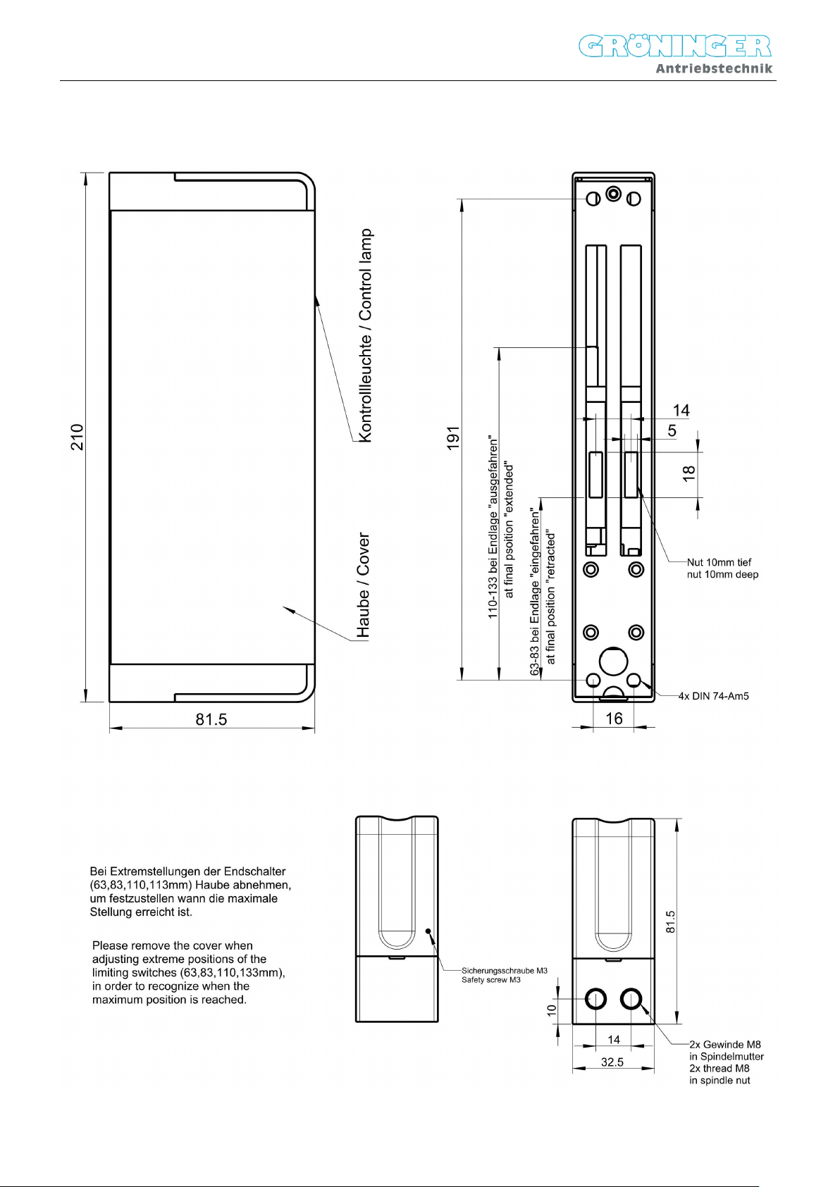
1.) M8- Gewindestange wird stirnseitig in die
Spindelmutter eingeschraubt. z.B. für
Oberlichtscheren. Entfernen Sie hierzu eine der
beiden stirnseitigen Abdeckstopfen und schrauben
Sie eine M8- Gewindestange in die Spindelmutter
fest ein.
2.)Zwei Nuten mit 5mm auf Unterseite des
Antriebs. Diese Abtriebsmöglichkeit ist abhängig
von der jeweiligen Fensterkonstruktion und wird oft
für Lamellenfenster verwendet.
Für die Montage und den Anschluss der Antriebe
ist zu beachten:
Die erforderlichen Leistungsdaten (siehe
„Technische Daten“) dürfen weder
überschritten noch unterschritten werden.
Die in den Maßzeichnungen angegebenen
Werte sind beim Einbau des Antriebs
einzuhalten.
Prüfen Sie, ob Ihre Anlage die nötigen
technischen und elektrischen
Vorraussetzungen erfüllt.
Beachten Sie immer alle landesüblichen
Bestimmungen für elektrische
Steuerungsanlagen sowie alle anderen
landesüblichen Bestimmungen.
Prüfen Sie immer, ob Ihre Anlage den gültigen
Bestimmungen entspricht.
Besondere Beachtung finden dabei:
- Querschnitt des Fensters
- Öffnungszeit/ -geschwindigkeit
- Temperaturbeständigkeit von Kabel
und Fensterantrieb
- Querschnitte der Kabel in der
Steuerungsanlage
Fenster und Fensterrahmen müssen für die
Belastung durch Druck- und Zugkraft des
Fensterantriebs ausgelegt sein.
Gefahren bei der Montage
Die Gewährleistung für einen sicheren Betrieb
hängt von der Einhaltung der
Sicherheitsvorschriften seitens der Monteure ab.
Handhabung und Montage bestimmter Teile und
Komponenten in ungeeigneter Art und Weise kann
unter ungünstigen Bedingungen zu Verletzungen
führen.
Verletzungsgefahr durch unsachgemäße
Handhabung! Körperverletzung durch Quetschen,
Scheren, Schneiden, Stoßen!
Die allgemeinen Errichtungs- und
Fit the drive onto the window in such a way that it is
accessible at any given time and can be exchanged
if necessary.
Two possibilities exist for the transmission of force
onto the window:
1.) M8-threaded rod is screwed into the spindle nut
on the frontal side e.g. for fanlight openers. In order
to do this, remove one of the frontal cover plugs and
tightly screw an M8-threaded rod into the spindle
nut.
2.) Two grooves of 5mm on the bottom of the drive.
This output possibility depends on the specific
window construction in question and is often used
for louvre windows.
For the assembly and installation of the drives,
please bear the following in mind:
The required performance values (please
see “Technical Data”) may be neither
exceeded nor undershot.
The values indicated on the dimension sheet
are to be complied with during the
installation of the drive.
Be sure to verify whether your facility meets
the necessary technical and electric
requirements.
Always respect all country specific
regulations for electric governance systems
as well as all other country specific
regulations.
Always verify whether your facility meets the
relevant requirements.
Pay special attention to the:
- Cross-section of the window
- Opening time/speed
- Temperature resistance of the cables
and drive
- Cross-section of the cables in the
governance system
The window and window frame must be constructed
according to the strain caused by the compressive
and tractive force of the drive.
Danger during assembly
The warranty for the safe operation is dependent on
the assemblers’ compliance with the safety
regulations. The handling and assembly of certain
parts and components in an inappropriate manner
may lead to injuries under unfavourable
circumstances.
Risk of injury through improper handling! Potential
injury through crushing, shearing, cutting, impact!
Follow the general construction and safety
instructions for handling and assembly.
Use suitable assembly and transport
facilities.
Prevent incarceration and crushing through

Gröninger Antriebstechnik GmbH & Co.KG Stand 05/18 Seite / Page 4
Sicherheitsvorschriften zur Handhabung und
Montage beachten.
Geeignete Montage- und
Transporteinrichtungen verwenden.
Einklemmungen und Quetschungen durch
geeignete Vorkehrungen vorbeugen.
Nur dafür geeignetes Werkzeug verwenden.
Hebeeinrichtungen und Werkzeug fachgerecht
einsetzen.
Wenn erforderlich, geeignete
Schutzausstattungen (z.B. Schutzbrille,
Sicherheitsschuhe) benutzen.
Nicht unter hängenden Lasten aufhalten.
-elektrisch
Achtung:
Den Antrieb nur mit 230 VAC betreiben.
Die elektrische Installation darf nur von
Elektrofachpersonal unter Beachtung der
Sicherheitsbestimmungen vorgenommen werden.
Die Anschlussleitungen dürfen weder auf Zug,
Verdrehung, Quetschung noch auf Abscherung
belastet werden.
Falls noch nicht geschehen, entfernen Sie die
Sicherungsschraube M3 an der stirnseitigen
Kunststoffabdeckung auf der Seite des
elektrischen Anschlusses. Entfernen Sie die
Abdeckungen, indem Sie diese nach oben
wegziehen.
Schließen Sie den Antrieb gemäß Anschlussplan
an. Den genauen Anschlussplan finden Sie am
Ende dieser Anleitung. Befestigen Sie das
Anschlusskabel unbedingt mit der dafür
vorgesehenen Zugentlastung!
Sollte während der Montage des Antriebs das
Schutzleiterkabel von der Haube entfernt worden
sein, oder falls der Antrieb mit separater Haube
ausgeliefert wurde, muss das Schutzleiterkabel
wieder mit der Haube elektrisch leitend verbunden
werden. Es muss geprüft und protokolliert werden,
dass der Widerstand zwischen Haube und
Klemme 5 (PE) max. 1Ω entspricht gemäß DIN
VDE 0100-600. Je nach Einbauort, sind weitere
länderspezifische Vorschriften zu beachten!
Der Antrieb ist für die Innenmontage geeignet und
sollte grundsätzlich mit einem Regensensor
betrieben werden.
Setzten Sie nach der Montage die stirnseitigen
Abdeckungen auf. Schrauben Sie auf der
suitable precautions.
Only use suitable tools.
Use lifting equipment and tools properly.
Use appropriate safety equipment (e.g.
safety goggles, safety shoes) when
necessary.
Do not stop beneath hanging loads.
-electric
Caution:
Only operate the drive with 230 VAC.
The electric installation may only be carried out by
professional electricians while following the safety
regulations. The connection cables may not be put
under the strain of twisting, crushing or shearing off.
In case it has not yet been done, remove the safety
screw M3 on the frontal plastic cover on the side of
the electric connection. Remove the plastic covers
by pulling them off in an upward direction.
Connect the drive according to the connection
diagram. The detailed connection diagram is
located at the end of this manual. It is crucial that
the connection cable is fastened using the
designated strain relief.
In case of disconnecting the ground wire from the
cover during mounting the drive or in case of
separate delivery of the cover and the drive, the
ground wire must be connected electrically
conducting. It must be tested and recorded that the
electrical resistance between the cover and terminal
5 (PE) is max. 1Ω according DIN VDE 0100-600.
According to the place of installation, further
country-specific regulations must be observed.
The drive is suitable for interior mounting and
should principally operate with a rain-sensor.
After assembly, be sure to place the front and rear
covers back onto the drive. It is essential that you
screw the safety screw M3 back into the plastic
cover on the side of the electric connection. Do this
until the screw is even with the surface of the cover.

Gröninger Antriebstechnik GmbH & Co.KG Stand 05/18 Seite / Page 5
elektrischen Anschlussseite unbedingt die
Sicherungsschraube M3 wieder in die
Kunststoffabdeckung ein, bis die
Sicherungsschraube eben mit der Oberfläche der
Abdeckung ist!
Inbetriebnahme
Überprüfen Sie vor der ersten Inbetriebnahme, ob
der Antrieb sachgemäß am Objekt befestigt wurde
(siehe Montage mechanisch und elektrisch) und
der elektrische Anschluss gemäß den oben
genannten Bestimmungen ausgeführt wurde.
Achten Sie dabei auf die elektrische Zuleitung und
prüfen Sie diese auf eventuelle Beschädigungen.
Lassen Sie die Zuleitung gegebenenfalls von einer
Elektrofachkraft austauschen.
Sind die oben genannten Anforderungen erfüllt,
können die beiden Endschalter eingestellt werden.
Die Endschalter werden durch Drehen mit einem
Schraubendreher an den stirnseitigen
Stellschrauben verstellt (Drehrichtung siehe
Anschlussplan). Die Endschalter müssen so
eingestellt werden, dass die Fenstermechanik und
der Antrieb nicht auf Block belastet wird.
Der Antrieb besitzt einen internen Thermoschalter,
der bei Erreichen einer hohen Motortemperatur
den Antrieb abschaltet. Dies stellt eine
Schutzmaßnahme des 230VAC- Motors dar, die
mechanische Beschädigungen nicht ausschließt.
Bei der Hubeinstellung durch die Endschalter ist
darauf zu achten, dass der jeweilige Endschalter
richtig abschaltet. Dann erlischt die
Kontrollleuchte. Die Kontrollleuchte darf in den
Endpositionen nicht aufleuchten!
Prüfen Sie vor der Inbetriebnahme ob die beiden
Endschalter sachgemäß eingestellt sind, um
Beschädigungen der Beschlags- oder
Fensterkonstruktion zu vermeiden!
Sind beide Endschalter eingestellt, müssen Sie
einen ersten Probelauf durchführen.
Betrieb
Die Nennlast wird nur bei Nennspannung erreicht.
Eine Unterschreitung reduziert die Nennlast!
Betrieb mit einem „Totmanntaster“
Bei Betrieb mit einer „Totmannschaltung“ (Tipp-
Taster) muss eine Bestromung bis zum Ende des
Schließvorgangs erfolgen.
Initial Operation
Before putting the drive into operation for the first
time, please verify whether the drive has been
properly fixed onto the respective object (please see
Assembly- mechanical and electric) and whether
the electric connection was carried out in
accordance with the requirements listed above.
Pay attention to the electric supply cables and
inspect these for potential damage. If necessary,
have a professional electrician exchange the supply
cables
If the requirements listed above have been met, the
two limiting switches may be adjusted. The limiting
switches are adjusted by turning the frontal setting
screws using a screwdriver (refer to connection
diagram for turning direction). The limiting switches
must be adjusted in such a way that the window
mechanics and the drive are not strained to block.
The drive has an internal thermal switch. When
reaching a high motor temperature, the drive
switches off. This is a overload protection for the
230VAC- Motor, which does not exclude
mechanical damages.
During the stroke adjustment through the limiting
switches, make sure that the respective limiting
switch has switched off correctly. If this is the case,
the control lamp will switch off. The control lamp
may not switch on in the final positions.
Before commencing with the initial operation, verify
whether the two limiting switches have been
adjusted correctly in order to avoid damage being
caused to the fitting or window construction! Once
both limiting switches have been adjusted, you must
conduct a first trial run.
Operation
The nominal load is only reached under the nominal
voltage. Falling under the nominal voltage reduces
the nominal load.
Operation with a “dead man’s push button”
During operation with a “dead man’s switch”, current
feeding must take place until the end of the closing
process.

Gröninger Antriebstechnik GmbH & Co.KG Stand 05/18 Seite / Page 6
Wartung
Verwenden Sie keinesfalls Laugen oder Säuren
zum Reinigen.
Alle 1000 Öffnungszyklen müssen folgende
Prüfungen durchgeführt werden:
- Prüfen Sie, ob alle Schrauben fest angezogen
sind, bzw. ziehen Sie diese ggfs. nach.
- Führen Sie eine Sichtkontrolle auf
Beschädigung und Verschleiß aller Bauteile
durch und tauschen diese ggfs. aus.
- Kontrollieren Sie die korrekte Einstellung der
Endschalter.
Mindestens einmal pro Jahr eine Sichtprüfung des
Netzkabels vornehmen. Es darf weder beschädigt
sein, noch dürfen sonstige Anzeichen von
Verschleiß oder Defekten vorhanden sein.
Unterbrechen Sie die Strom- und
Spannungsversorgung des Motors während den
Reinigungs- und Wartungsarbeiten.
Störungen beheben
Falls der Antrieb stehen bleibt, lassen Sie bitte die
elektrische Versorgung durch eine Elektrofachkraft
überprüfen.
Tauschen Sie bei nicht von Fachleuten
behebbaren Störungen den defekten Antrieb aus
und lassen ihn vom Herstellerwerk reparieren.
Einbauerklärung
Hiermit erklären wir (Gröninger Antriebstechnik
GmbH & Co. KG; Alte Str. 9; D-72631 Aichtal)
dass die unvollständige Maschine Fensterantrieb
LS 1400 alle grundlegenden Anforderungen der
Richtlinie 2006/42/EG des europäischen
Parlament und des Rates vom 17.05.2006 über
Maschinen und zur Änderung der Richtlinien
95/16/EG (Neufassung) erfüllt Darüber hinaus
entspricht die unvollständige Maschine der
elektromagnetischen Verträglichkeit gemäß der
Richtlinie 2014/30/EU des europäischen
Parlaments und des Rates vom 26.02.2014 zur
Angleichung der Rechtsvorschriften der
Mitgliedsstaaten über die elektromagnetische
Verträglichkeit und zur Aufhebung der Richtlinie
89/336/EWG und es wird die Richtlinie
2014/35/EU des europäischen Parlaments und
des Rates vom 26.02.2014 zur Angleichung der
Rechtsvorschriften der Mitgliedsstaaten betreffend
der elektrischen Betriebsmittel zur Verwendung
Maintenance
Under no circumstances should alkaline or acidic
solutions be used for cleaning purposes.
The following tests need to be carried out after
every 1000 opening-cycles:
- Inspect whether all screws are tightly
fastened and retighten them if necessary.
- Visually inspect all components for any signs
of damage or wearing out, and replace these
if necessary.
- Ensure that the limiting switches are set
correctly.
At least once a year, conduct a visual inspection of
the power cable. It may not be damaged, nor may
any signs of wearing out or faults exist.
Discontinue the current and power supply of the
motor during the cleaning and maintenance
process.
Rectifying disturbances
In case the drive stops running, please have a
professional electrician examine the electricity
supply.
If the disturbances cannot be rectified by qualified
professionals, replace the faulty drive and have the
manufacturer repair it.
Declaration of Incorporation
We (Gröninger Antriebstechnik GmbH & Co. KG;
Alte Str. 9; D-72631 Aichtal) hereby declare that the
incomplete machine window-drive LS 1400 fulfils all
the fundamental requirements of the guideline
2006/42/EG of the European Parliament and
Council of the 17.05.2006 about machines and for
the annulment of the guidelines 95/16/EG (revised
version). Furthermore, the incomplete machine
corresponds with the electromagnetic compliance in
accordance with the guideline 2014/30/EU of the
European Parliament and Council of the 26.02.2014
for the alignment of the legislation of the member
states concerning the electromagnetic compliance
and for the annulment of the guidelines
89/336/EWG and the guideline 2014/35/EU of the
European Parliament and Council of the 26.02.2014
for the alignment of the legislation of the member
states concerning the electrical equipment to be
used within certain voltage limits for electrical
equipment were complied with.

Gröninger Antriebstechnik GmbH & Co.KG Stand 05/18 Seite / Page 7
innerhalb bestimmter Spannungsgrenzen für
elektrische Betriebsmittel eingehalten.
Bevollmächtigt, die relevanten technischen
Unterlagen zusammen zu stellen, ist Herr Matthias
Gröninger.
Die speziellen technischen Unterlagen gemäß
Anhang VII B der Richtlinie 2006/42/EG wurden
ordnungsgemäß erstellt.
Wir verpflichten uns, staatlichen Stellen auf
begründetes Verlangen die speziellen Unterlagen
zu der oben bezeichneten unvollständigen
Maschine zu übermitteln. Die Übermittlung erfolgt
in der Weise, wie sie von der staatlichen Stelle
verlangt wird.
Die Inbetriebnahme der unvollständigen Maschine
ist erst dann zulässig, wenn gegebenenfalls
festgestellt wurde, dass die Maschine, in die die
unvollständige Maschine eingebaut werden soll,
den Bestimmungen der Richtlinie 2006/42/EG
entspricht.
Aichtal, 25.05.2018; Gröninger, Matthias,
Ort, Datum Name, Vorname
Geschäftsführer der Gröninger Antriebstechnik
Gmbh & Co. KG; Alte Str. 9, D-72631 Aichtal
Mr. Matthias Gröninger is authorised to compile the
relevant technical documents.
The special technical documents according to
attachment VII B of the guideline 2006/42/EG have
been compiled in accordance with the regulations.
Upon justified request, we pledge to provide state
authorities with the special documents for the
incomplete machine described above. The
conveyance of the documents will be carried out as
requested by the state authority.
Starting the operation of the incomplete machine is
only permitted once it has been established that the
machine into which the incomplete machine is to be
incorporated, fulfils the regulations of the guideline
2006/42/EG.
Aichtal, 25.05.2018; Gröninger, Matthias,
Loaction, Date Surname, Name
Managing director of Gröninger Antriebstechnik
GmbH & Co. KG; Alte Str. 9, D-72631 Aichtal

Gröninger Antriebstechnik GmbH & Co.KG Stand 05/18 Seite / Page 8
Technische Daten / Technical Data
Versorgung
Stromaufnahme
Leistungsaufnahme
Einschatldauer
Supply
Current consumption
Power input
Duty ratio
230 V AC ± 10 %; 50Hz
0,4 A
90 W
ED 25% (150s ON / 450s OFF)
Druckkraft bei 230 V AC
Zugkraft bei 230 V AC
(an M8- Gewindestange)
Compressive force at230 V AC
Tractive force at 230 V AC
(at M8- threaded rod)
1400 N
1400 N
Hublänge Stroke lentgth Max. 70 mm
Laufzeit AUF / ZU Running time OPEN / CLOSE Ca.1,2 mm/s bei / at 1400N
Schutzart
Temperaturbereich
Überlastschutz
Protection type
Temperature range
Overload protection
IP 20
-15°C +70°C
Thermoschalter / Thermal switch
Anschluss
Gehäuse
Connection
Casing
Anschlußstecker / Connector
Aluminium, Kunststoff /
Aluminium, Plastic
Abmessungen (B x H x L) Dimensions (w x h x l) 32.5 x 81.5 x 210mm

Gröninger Antriebstechnik GmbH & Co.KG Stand 05/18 Seite / Page 9
Massblatt / Dimension Sheet

Gröninger Antriebstechnik GmbH & Co.KG Stand 05/18 Seite / Page 10
Anschlussplan / Connection Diagram
This manual suits for next models
1
Table of contents
Popular Industrial Equipment manuals by other brands

RINGFEDER
RINGFEDER TNM GBT Series Installation and operation manual

SCHUNK
SCHUNK JGP-P Assembly and operating manual

Eaton
Eaton Digitrip Retrofit System Instruction leaflet

Ecoflam
Ecoflam GT-D1-GBLE055-RP15-MAXGAS40-120 manual

SPE
SPE MS230 operating manual

Mid-West Instrument
Mid-West Instrument 522 Installation and operating instruction