Grace Company Quilter's Evolution Elite Quick setup guide

Copyright July 25, 2022
www.graceframe.com
1-800-264-0644
ELITE-FRAME
Version 1.0
12 Foot Frame Assembly & Use

My Frame Details
Use this page to record information about your frame. This will be helpful if you ever need to call a
Grace Company support technician.
Frame Type: ________________________________________
Date of Purchase: ____________________________________
What Machine are You Using? __________________________
Select Which Frame Accessories You Have Purchased:
Quilter’s Evolution Elite 12-Foot
• Start-Right Cloth Leaders
• QuiltMotion
• Pattern Perfect
• G-Series Top Plate
• Power Strip Accessory
• Speed Control
• Gracie Laser
• Sure Stitch
• Sure Stitch Elite
• Luminess Light Bar

i
Warranty Information
X
?
1-800-264-0644
The Quilter’s Evolution Elite-Frame has a one-year limited warranty on all parts. The
Grace Company will repair or replace, at its discretion, any part with problems due to
our manufacturing or defects in materials. This warranty does not cover parts damaged
through misuse, improper storage, improper assembly, loss, natural events, and willful
destruction. Parts must be returned to Grace Company, shipping prepaid, before we
can repair or replace them. We will promptly return the repaired/replaced part at our
expense if done within a year of the purchase date.

ii
We are pleased to introduce you to the newest part of your quilting setup. This frame has been
especially designed to help quilters like you have the tools available to create quality projects.
This manual is broken into four sections (or parts). Notications at the end of each section will
direct you to switch to your machine manual or QuiltMotion manual for instructions on assembling
those products. This creates a streamlined process of building a complete quilting setup in the most
ecient way. Use the following owchart to guide you in navigating multiple manuals. If you are not
using one of the products in the owchart, just move to the next item in the chart.
Thank you again for choosing us to help your quilting projects. We look forward to working with you.
- The Grace Company
Start Here: Frame Manual: Part One
• Assemble the frame’s legs, table, and sides.
• Install the channel lock onto the bottom
carriage.
• Align your tracks.
Quilting Machine Manual: Part One
• Install the lower encoder onto the bottom
carriage.
QuiltMotion Manual: Part One
• Install the motor plate and power strip onto
the bottom carriage.
• Install the long belt across the frame.
Quilting Machine Manual: Part Two
• Install your machine’s wheels.
• Align your wheels.
QuiltMotion Manual: Part Two
• Install the short belt.
• Tension the short belt.
Welcome to Your Quilter’s Evolution Elite

iii
Frame Manual: Part Two
• Install the channel lock on the machine or
top plate.
Quilting Machine Manual: Part Three
• Install the wheel covers, display, handles,
thread mast.
• Install the upper encoder.
Frame Manual: Part Three
• Install the rails and fabric bungees.
• Position and adjust the rails.
• Level the frame.
QuiltMotion Manual: Part Three
• Install the tablet bracket.
• Plug in QuiltMotion.
• Use the quilting modes and settings in the
display.
• Maintain the machine and perform repairs.
Quilting Machine Manual: Part Four
Frame Manual: Part Four
• Install the cloth leaders.
• Attach the fabric.

iv
Contents
Welcome to Your Quilter’s Evolution Elite.................................................................................ii
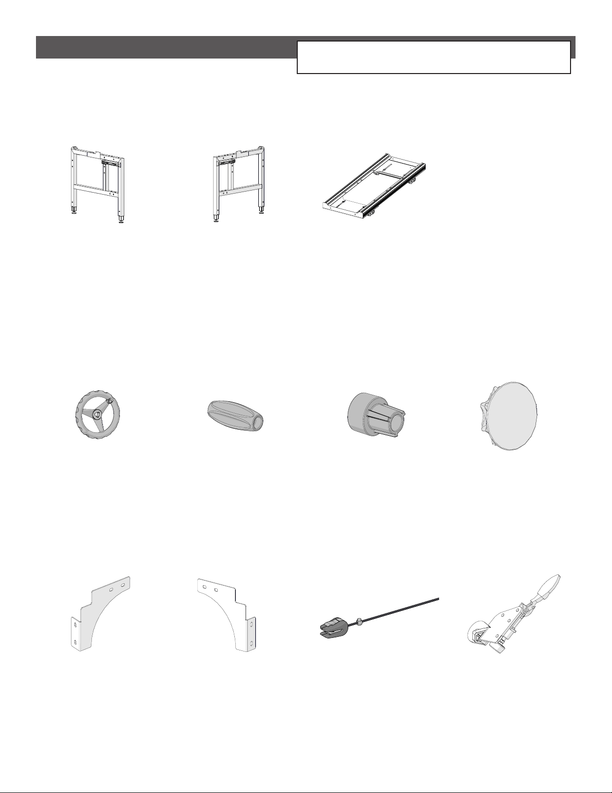
Included Parts and Tools ........................................................................................................v
Animated Instructions ......................................................................................................... xiv
Part One .......................................................................................... 1
Task 1 - Setting the Frame Height.......................................................................................... 2
Task 2 - Assembling the Tracks .............................................................................................. 6
Task 3 - Installing the Table..................................................................................................16
Task 4 - Attaching the Braces ...............................................................................................22
Task 5 - Installing the Take-Up Rail Towers............................................................................27
Task 6 - Installing the Side Rail Assemblies............................................................................29
Task 7 - Attaching the Tracks................................................................................................32
Task 8 - Installing the Carriage Channel Lock.........................................................................37
Part Two ........................................................................................ 41
Task 9 - Installing the Machine Channel Lock.........................................................................42
Part Three...................................................................................... 45
Task 10 - Assembling the 12 Foot Rails..................................................................................46
Task 11 - Installing the Front Rails ........................................................................................52
Task 12 - Installing the Take-up Rail......................................................................................57
Task 13 - Positioning the Rails ..............................................................................................62
Task 14 - Installing the Bungee Clamps .................................................................................74
Task 15 - Leveling the Frame................................................................................................76
Part Four........................................................................................ 81
Task 16 - Installing the Cloth Leader Velcro ...........................................................................82
Task 17 - Installing the Cloth Leaders....................................................................................86
Building Your Quilt Sandwich ................................................................................................88
Attaching Your Quilt to the Frame .........................................................................................89
Using the Bungee Clamps...................................................................................................100
Tacking Down Your Quilt ....................................................................................................102
Using a Test Fabric Swatch .................................................................................................103
Rolling Your Fabric .............................................................................................................104
Using the Channel Locks ....................................................................................................107
Getting Started..................................................................................................................108

v
Included Parts and Tools
Left Side Leg
Assembly
Right Side Leg
Assembly
Corner
Brace A (x2)
Corner
Brace B (x2)
Box 1
Bottom Carriage
Assembly
CNT-09-13523
BOX 1: INNER HARDWARE BOX
QEF-04-15543 QEF-04-15544
QEF-09-16563QEF-09-16529
Large Hand Wheel
PLA-05-11550
Large Hand Wheel
Knob
PLA-05-11551
Hand Wheel
Collar
PLA-05-11552
Quilt-Backing Rail
Press-In Cap
QEF-05-16498
Bungee Clamps
(4 pack)
ACC-01-10261
Dual-Wheel
Channel Lock (x2)
ACC-09-13057
Your kit comes with boxes 1, 2, 4, 6, and 7.
This frame setup does not use boxes 3 or 5.

vi
SBHCS
M10 x 55 mm
HDW-03-11605
Hand Wheel
Washer
HDW-03-13035
Hand Wheel Handle
Bolt M8 x 85 mm
HDW-03-11195
BOX 1: INNER HARDWARE BOX (continued)
10
13
Open End Wrench
10 mm and 13 mm
HDW-03-10743
17
14
Open End Wrench
14 mm and 17 mm
HDW-03-12347
HDW-03-14970
SBHCS
M8 x 20 mm (x4)
HDW-03-10951
SBHCS
M8 x 16 mm (x32)
Allen Wrench
5 mm
HDW-03-10741
Allen Wrench
2.5 mm
HDW-03-10165
Allen Wrench
6 mm
HDW-03-10742
T-handle Allen
Wrench 4 mm
4 mm
HDW-03-13114
3-Wing Knob
M8 x 16 mm (x2)
C11-03-14895
Included Parts and Tools (continued)

vii
HDW-03-10088
SBHCS
M6 x 20 mm (x2)
BOX 1: INNER HARDWARE BOX (continued)
M8
Washer (x4)
HDW-03-10733
SBHCS
M8 x 55 mm (x4)
HDW-03-10726
Included Parts and Tools (continued)

viii
Included Parts and Tools (continued)
Front Rail
Clamp (x2)
QEF-05-16505
5 ft Table with
Tracks Assembly
QEF- 09-16576
Box 2
5 ft Star Rail
Assembly
ACC-09-16567

ix
Take-Up Rail
Tower Right
QEF-09-17034
Take-Up Rail
Tower Left
QEF- 09-17030
Square Side Rail
Assembly - Left
QEF- 09-17058
Square Side Rail
Assembly - Right
QEF- 09-17044
Logo Plate (x2)
ACC-09-16565
Box 4
5 ft Round Rail
Assembly (x2)
QEF-09-17068
BOX 4: INNER BOX 1
BOX 4: INNER BOX 2
BOX 4: INNER BOX 1: HARDWARE BOX
Start Right Cloth
Leader Set
ACC-01-10750
Frame Reference
Card Hook
HDW-03-16369
38 mm
Tube Cap (x2)
BER-05-14868
Allen Wrench
3 mm
HDW-03-10166
Included Parts and Tools (continued)

x
Included Parts and Tools (continued)
Box 6
5 ft Table Assembly
- 5 ft Extension
QEF- 09-17087
Star Rail - 5 ft
QEF-04-15537
Middle Leg
QEF- 09-17102
Middle Table
Brace (x2)
QEF-04-15545
Round Rail -
5 ft (x2)
CNT-04-1105
10 ft
Plastic Track
PLA-05-10560
Star Rail Coupler
QEF-09-17096
Rail Coupler
Assembly (x2)
CNT- 09-11865
Front Rail
Clamp (x2)
QEF-05-16505

xi
BOX 6: INNER HARDWARE BOX
SBHCS
M10 x 100 mm (x2)
HDW-03-14602
Washer M10 (x2)
HDW-03-10952
Nylock Nut M10 (x2)
HDW-03-16817
SBHCS
M8 x 16 mm (x16)
HDW-03-10951
Socket CSS
M6 x 6 mm (x16)
HDW-03-16818
Track Support
Connector (x4)
CNT-04-11041
Included Parts and Tools (continued)
The instruction manual for the 10 foot frame assembly
is not needed for this setup and can be discarded.

xii
Included Parts and Tools (continued)
Box 7
Middle Leg
QEF- 09-17102
Star Rail Coupler
QEF-09-17096
Rail Coupler
Assembly (x2)
CNT- 09-11865
Star Rail - 2 ft
QEF-04-15538
2 ft Rail (x2)
MET-04-11397
2 ft Table
Assembly
QEF- 09-17151
Middle Table
Brace (x2)
QEF-04-15545
12 ft
Plastic Track
PLA-05-10561
Front
Rail Clamp
QEF-05-16505

xiii
BOX 7: INNER HARDWARE BOX
SBHCS
M10 x 100 mm (x2)
HDW-03-14602
Washer M10 (x2)
HDW-03-10952
Nylock Nut M10 (x2)
HDW-03-16817
SBHCS
M8 x 16 mm (x16)
HDW-03-10951
Socket CSS
M6 x 6 mm (x8)
HDW-03-16818
Track Support
Connector (x2)
CNT-04-11041
Included Parts and Tools (continued)

xiv
To provide the best possible customer experience, we also oer animated video instructions for
setting up this product. To view the animated instructions, visit our website at:
https://l.ead.me/QEelitestart
You can also use your smartphone to scan this QR code:
Animated Instructions

1
Part One
Part One
Complete Part One of these instructions before assembling your quilting machine or any accessories.
At the end of each part, you will be instructed to switch to specic sections of your machine manual,
QuiltMotion manual, or other accessory manuals, if you are preparing to assemble them at this time.
If you have not made those purchases, simply skip those steps.

2
Task 1 - Setting the Frame Height
Part One
Parts & Tools Needed:
Instructions
The frame height is important for comfortable prolonged use. Ideally, the handlebars on your
machine or top plate will be around elbow height once your setup is fully assembled. Take the
following steps to set your frame height:
10
13
Open-End Wrench
10 mm and 13 mm Tape Measure
(not included)
Left Side Leg Assembly Right Side Leg
Assembly
(Box 1) (Box 1)
Allen Wrench
5 mm
(Box 1: Hardware Box) (Box 1: Hardware Box)
Loosen the two set screws at the base of the left leg with the 4 mm T-handle Allen wrench.
1
Set Screws
(Box 1: Hardware Box)
T-handle Allen
Wrench 4 mm
4 mm
Middle Leg (x2)
(Box 6 and Box 7)
Left Leg

3
Use the 13 mm open-end wrench to hold the nut and use the 5 mm Allen wrench to unscrew
the height screw. Remove both sets of height screws, washers, and nuts from the leg.
Height Screw (x2) Washers (x2)
Nuts (x2)
Part One
Task 1 - Setting the Frame Height (continued)
While standing straight, hold your arm at a 90 degree angle. Use a tape measure to measure the
distance in inches from your elbow to the oor.
3
2

4
Part One
Task 1 - Setting the Frame Height (continued)
Find the hole number closest to your elbow height in the chart. Then pull out the bottom part of
each leg to align its two screw holes with the hole you’ve chosen in the bottom part of the leg.
Set all legs to the same hole.
4
5Secure in place with the screws, washers, and nuts. Tighten with the 5 mm Allen wrench and
13 mm open-end wrench.
Hole Number Elbow to Floor
1 40 Inches
2 41 Inches
3 42 Inches
4 43 Inches
5 44 Inches
6 45 Inches
7 46 Inches
8 47 Inches
9 48 Inches
9
8
7
6
5
4
3
2
1
Table of contents
Other Grace Company Indoor Furnishing manuals
Popular Indoor Furnishing manuals by other brands

Evenflo
Evenflo Barn Door Walk-Thru manual

Eureka Ergonomic
Eureka Ergonomic PYTHON II ERK-GC08-BU manual

Prosedia
Prosedia Younico PRO Assembly and operating instructions

Sauder
Sauder Carson Forge Collection 415117 Instruction

Next
Next BARLOW 501758 Assembly instructions

Girsberger
Girsberger Yanos A quick guide