Grace Industries WorkForce 1 Operation manual

Grace Industries, Inc.
WorkForce®1
Model WF1
User’s Information
WorkForce WF1 UI 2021-11
Micro B USB Connection
for Conguration
and Battery Charging
Antenna
Emergency
Alarm
Button
Piezo
Sounder
Alarm Ring
LEDs
Side Button
Side Button
Top LED Indicators (4)
System Status
Indicators
(4 Side LEDs)
Rear View
with Grip Clip
for attachment
Top Button
WorkForce® model WF1 is a worker-worn motion-
sensing Man-Down Alarm that uses independent, high
performance RF (radio-frequency) wireless signaling
to help protect workers in dangerous and hazardous
environments.
WorkForce® provides real-time motion-sensing, includ-
ing fall-detection, and contains an Emergency Alarm
Button to immediately transmit a distress alarm signal.
WorkForce® Alarm Monitoring (AM) version also
receives distress alarm signals from other workers
equipped with WorkForce® and alerts the user with
audible and visual indicators. Other emergency
signaling features of WorkForce® include Evacuate, PAR,
Roll-Call and optional Out-of-Range indication.
A complete worker safety system can be achieved
by using additional Grace monitoring products with
locating capabilities.

Grace Industries, Inc. 2
Operating Instructions
(90 seconds to Alarm used for example)
ACTIVATING WorkForce®: Simultaneously pressing both side
buttons turns the WorkForce® ON and activates Sensing Mode.
In Sensing Mode, the device is monitoring radio trac for alarm
messages. The WorkForce® is also sensing motion, if enabled.
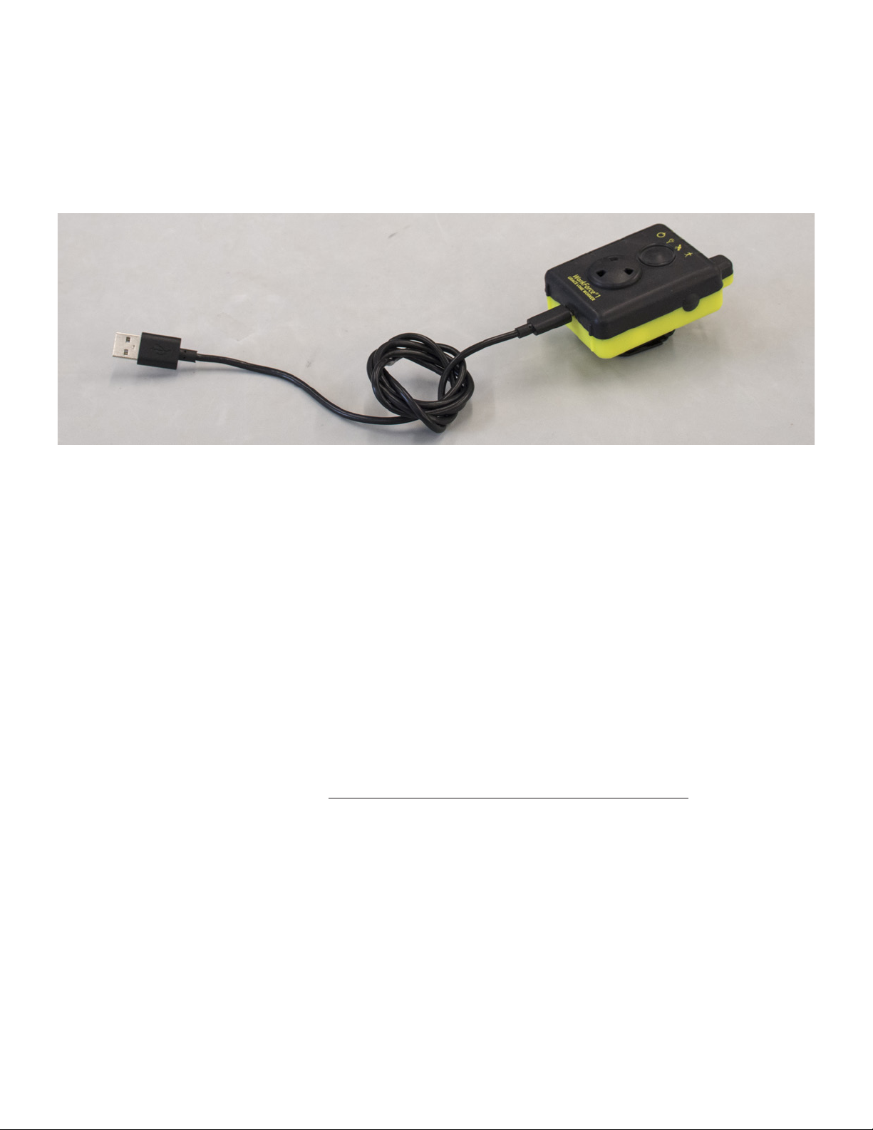
When Auto-ON/OFF setting is enabled, disconnecting the unit from
the charger adapter will activate WorkForce® and put into Sensing
Mode.
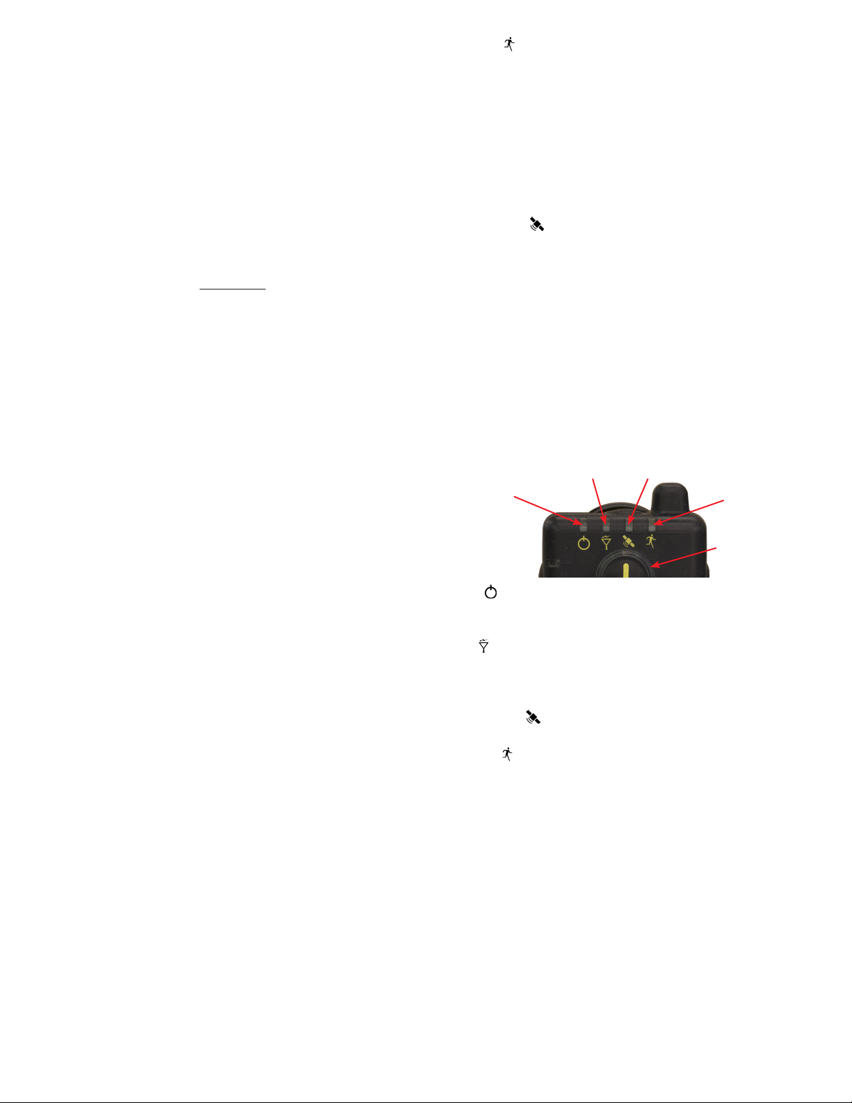
During activation, an operational signal of escalating audio tones
will be heard and the Power Indicator (at upper left) will begin to
blink approximately once per second. A pair of Green LEDs in the
Alarm Ring will begin ashing in an alternating display to indicate
motion is being sensed.
When WorkForce® is activated, its internal radio transmits signals
to other GRACE devices and equipment.
PRE-ALERT MODE: When a user remains motionless, a Pre-Alert
warning will begin to sound approximately 12 seconds before go-
ing into Alarm Mode. When no motion is sensed for approximately
78-83 seconds, WorkForce® begins an audible Pre-Alert sound and
an alternating Yellow LED display in the Alarm Ring. If motion is de-
tected during Pre-Alert, WorkForce® will reset into Sensing Mode.
ALARM MODE: There are 2 methods of activating Alarm Mode.
1) MOTION ALARM: After 90 to 95 seconds of no motion,
WorkForce® enters the Alarm Mode.
2) PANIC ALARM: WorkForce® user can activate Alarm Mode at
any time (from Sensing Mode or OFF Mode) by pressing the
Emergency Alarm Button.
ALARM MODE: Is indicated by a rapid pulsing of Red LEDs in the
Alarm Ring while sounding a loud audio alarm. During alarm, an
emergency radio signal is transmitted to other GRACE devices and
equipment, alerting personnel that personnel may need assistance.
RESET Alarm Mode: Return WorkForce® to Sensing Mode by si-
multaneously pressing both side buttons.
OFF: When in Sensing Mode, turn OFF by simultaneously pressing
and holding both side buttons for approximately 3 seconds until
a series of de-escalating audio tones are heard and all LED activity
cease. When Auto-ON/OFF setting is enabled, connecting the unit to
the charger adapter will turn the WorkForce® OFF.
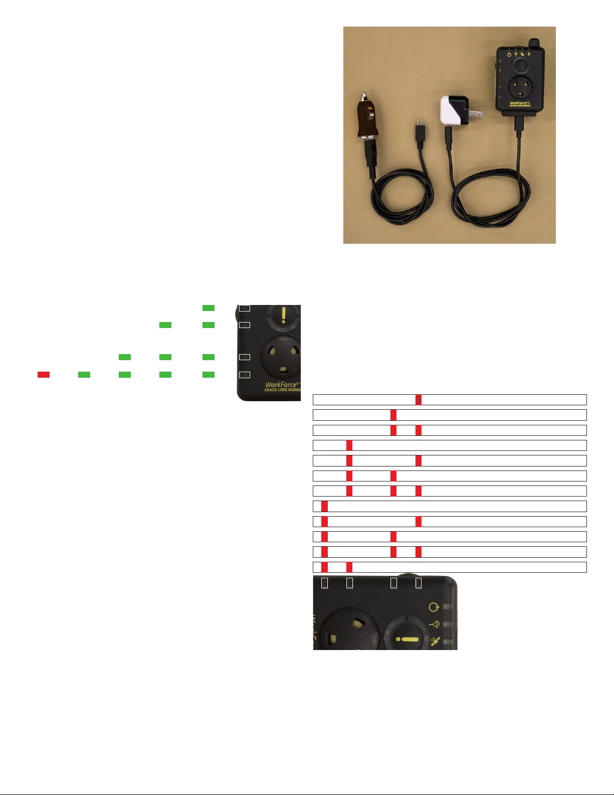
SYSTEM LOOP TEST: When in Sensing Mode, press and hold
top button until a rapid tri-tone conrms the device has sent
Loop Test Message and the countdown timer has started. A
successful Loop Test is indicated by an escalating tri-tone and
side LEDs 4-1 blinking yellow in an upward sequence. If the
Loop Test Acknowledge message is NOT received within the
congured timeframe, a de-escalating tri-tone will be heard.
NOTE: see Device Settings, pg.10, to enable/disable this System
Loop Test feature.
Operation of Special Features
EVACUATION ACKNOWLEDGMENT: If an Evacuate message is
received by the WorkForce®, it can be manually acknowledged by
simultaneously pressing both side buttons.
ALARM MONITORING: Allows the user to monitor the status of
other personnel working in the same general area when they are
equipped with WorkForce® or other GRACE devices. WorkForce®
MUST be in the Sensing Mode to receive Alarm signals from other
Grace devices or equipment.When one device goes into Alarm and
an Alarm Monitoring WorkForce® receives the signal, the Red side
LEDs will ash in an alternating pattern. This alert can be cleared
for one minute by pressing both side buttons simultaneously. If
additional GRACE devices go into Alarm during this one-minute
period, the Alarm Monitoring LED display will be reactivated. This
cycle will continue until the telemetry unit in Alarm is reset or shut
o.
NOTE: If an alarm has been received, the WorkForce® will not turn o
until the alarm has been cleared or reset.
FALL DETECTION:
WorkForce® is capable of detecting a fall of greater than 4ft. If a fall
is detected, the device will enter the Fall Pre-Alert state for 15 sec-
onds to allow the user to reset the WorkForce® after a false trigger
or a fall that does not require assistance. Fall Pre-Alert can only be
reset by simultaneously pressing both side buttons. If the Fall Pre-
Alert is not reset within 15 seconds the device will automatically
enter the Fall Alarm mode. This will send out a Fall Detected Alarm
message to any compatible Grace monitoring equipment.
FALL PRE-ALERT MODE: Is indicated by alternating Yellow LED
display in the Alarm Ring, and a double beep after the Pre-Alert
tone. Fall Pre-Alert may be cleared by simultaneously pressing
both side buttons.
FALL ALARM MODE: Is indicated by rapid pulsing of the Red LED’s
in the Alarm Ring while sounding a loud audio alarm with a double
beep. Clear the Fall Alarm by simultaneously pressing both side
buttons.
IMPORTANT NOTE: WorkForce® model WF1 cannot detect every
possible type of ‘fall’-event and it is the user’s responsibility to
be trained to always push the Emergency Alarm button, if they
are able, following any type of ‘fall’-event.
SIGNAL-LOST/OUT-of-RANGE OPERATION:
Signal-Lost/Out-of-Range is an indication that the user is
beyond the eective signaling range of theWorkForce® and a Grace
monitoring device or unit, such as a Grace GMG or GFG Gateway,
MS2000, SMS or GraceWatch® system. This feature operates using
2 way signaling between the WorkForce and the monitoring unit
for the purpose of indicating to the user they may be out of the
eective signaling range of the system.
When this feature is enabled and under normal operation,
the user will receive notication they are in the eective
signaling range on the monitoring device within 30 seconds after
powering on the WorkForce®.
This feature can be enabled through the PC software
conguration tool. If this feature was not enabled, verify there is
a Grace monitoring device that present that supports Signal-Lost/
Out-of-Range notication and is congured to actively operate
with the WorkForce® units.
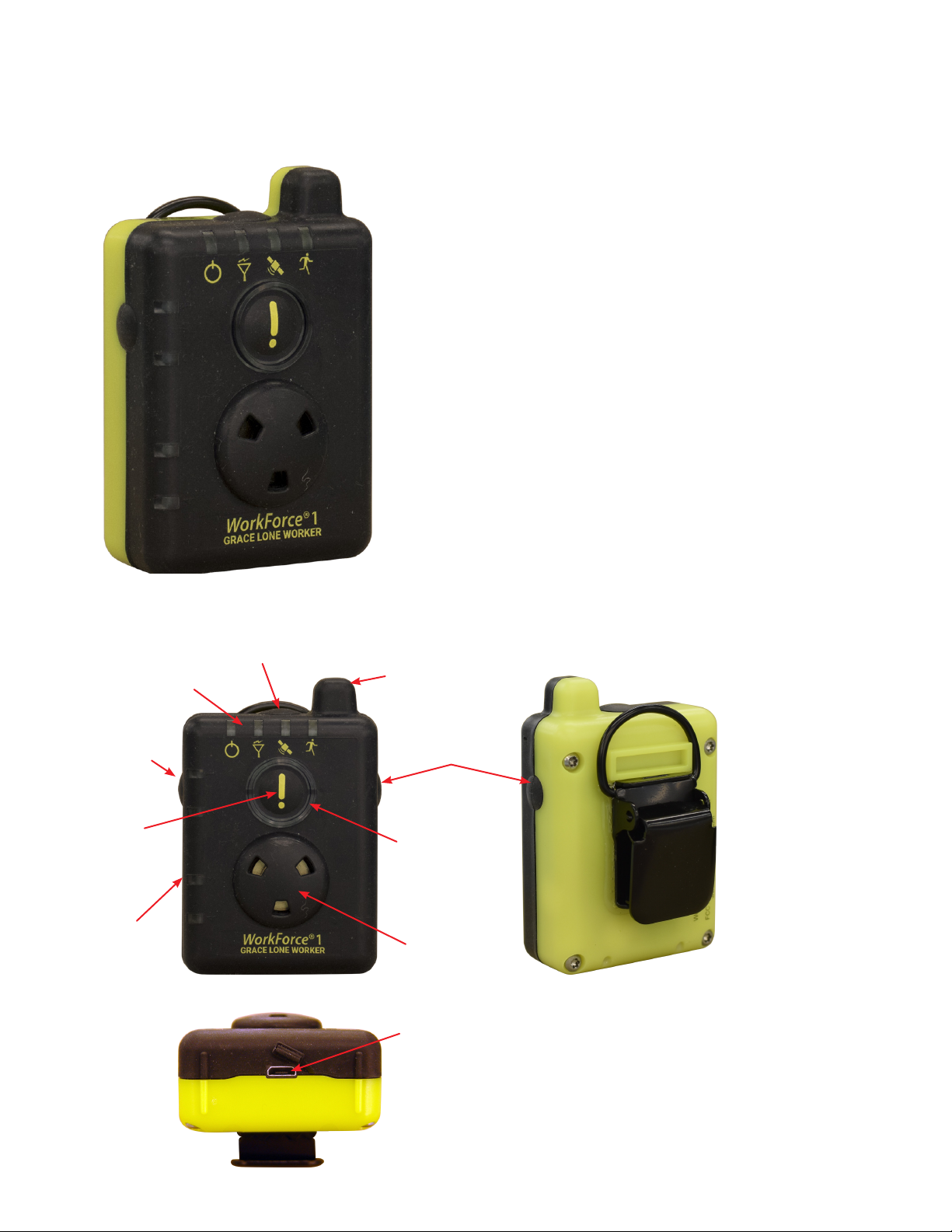
WorkForce® Mounting and Attachment
WorkForce® is equipped with a high-strength grip-clip designed
for secure attachment to personnel gear such as to a vertical strap
on the upper left or right shoulder with the sound port facing out,
or on the right or left hip area. The optional swivel-clip attachment
Read Instructions Before Use
Always test WorkForce® prior to use

Grace Industries, Inc. 3
is designed to clip onto a horizontal belt or strap. However, the
ideal wearing position of WorkForce® is often best determined
by the end user for ease of access and operation.
IMPORTANT NOTE: For WorkForce® to properly sense a falling
motion, the device must be securely attached to the user.
Mode Selection
ON (Sensing Mode)
• Simultaneously press both side buttons to activate
WorkForce® and put into Sensing Mode.
• Auto-ON: when Auto-ON/OFF setting is enabled, WorkForce®
is activated and put into Sensing Mode by disconnecting the
unit from charger adapter plugged into appropriate power
source. NOTE: if power source is disconnected or lost (i.e. power
outage), the WorkForce® will turn ON.
ALARM
• Alarm Mode can be manually activated at any time (from
Sensing Mode or O Mode) by pressing the Emergency
Alarm Button.
RESET
• When in Alarm or receiving an EVACUATE signal, RESET
WorkForce® to Sensing Mode by pressing both side buttons
simultaneously.
OFF
• When in Sensing Mode, turn OFF by simultaneously pressing and
holding both side buttons until the unit deactivates.
• Auto-OFF: when Auto-ON/OFF setting is enabled, Work-
Force® is turned OFF by connecting the unit to charger adapt-
er plugged into an appropriate power source.
SYSTEM LOOP TEST
• When in Sensing Mode, press and hold top button until a
rapid tri-tone conrms the device has sent Loop Test Message
and the countdown timer has started.
• SUCCESSFUL Loop Test is indicated by an escalating tri-tone
and side LEDs 4-1 blinking yellow in an upward sequence.
• FAILED TEST: If the Loop Test Acknowledge message is NOT
received within the congured timeframe, a de-escalating tri-
tone will be produced.
Visual / Audio Mode Display
OFF
• No LED Display.
ON (Sensing Mode)
• A series of escalating, loud audio tones.
• Green alternating LED display in Alarm Ring.
• Power LED ashing approximately once per second.
PRE-ALERT
• No motion sensed for 78-83 seconds.
• Amber alternating LED display in Alarm Ring.
• Loud, sweeping audio tones.
ALARM
• No motion sensed for 90 to 95 seconds.
• Rapid pulsing of Red LEDs in Alarm Ring.
• Loud audio alarm.
• Audio Alarm pauses briey as an aid for determining direction
when personnel need assistance.
• Radio LED ashes Red when transmitting the emergency radio
signal.
EVACUATE
• Running Man LED Flashes Red when receiving EVACUATE signal
from another Grace device or equipment.
Signal Lost / Out-of-Range Notication
• 3 audio down-sweeping tones.
• 3-second vibration.
• This notication repeats every minute until signal is regained
Signal Active / In Range Notication
• 3 audio up-sweeping tones.
• 3 short vibration pulses.
SATELLITE-GPS
• Slow blinking Green LED when GPS signal is acquired.
• Slow blinking Red/Green LED when NO GPS signal is detected.
LOW BATTERY
• Power LED blinks Red when battery charge is below 25%.
• Double chirp sound every ve (5) minutes if audio is enabled.
• NO power-on tones.
SYSTEM LOOP TEST
• Loop Test Initiated: Rapid tri-tone.
• Successful Loop Test: Escalating tri-tone is produced and side
LEDs blinking in upward sequence.
• Failed Loop Test: De-escalating tri-tone.
WorkForce®1 Top LED Indicators
ALARM Ring
Status LEDs
Power
Radio Satellite-GPS
EVACUATE
POWER When WorkForce® is ON, Power LED blinks Green
approximately once per second. LED blinks Red when battery level
is below 25%.
RADIO Flashes Red when transmitting radio signals. Flashes
Green when receiving radio signal from other GRACE devices or
equipment. Alternating Green/Red ashing indicates Signal Lost/
Out-of-Range Notication.
SATELLITE-GPS For GPS Equipped devices, the Satellite LED dis-
plays status of GPS x. LED blinks Green when a GPS x is acquired.
EVACUATE Displays EVACUATION status of the WorkForce®.
Flashes Red when receiving an EVACUATE signal.
ALARM RING STATUS LEDs: LED ring surrounding Emergency Alarm
Button.
• Rapid pulsing Red LEDs when in Alarm.
• Alternating Yellow LEDs when in Pre-Alert.
• Alternating Green LEDs when in Sensing Mode.

Grace Industries, Inc. 4
System Status (Side) LED Indicators
The System Status LEDs perform several functions. Four (4) Red/
Green LEDs are numbered 1 through 4 and arranged along the left
side of the device beginning with #1 at the upper left and #4 at the
lower left.
Alarm Monitoring (AM): If AM is enabled, Red LEDs will ash in an
alternating pattern when an Alarm signal is received from a GRACE
Man-Down device.
System Fault Detected: If a System Fault is detected, the LEDs will
indicate the detected fault. (Please see Troubleshooting chart/dia-
gram on Page 4 for detailed information).
Battery Power Level: When either side button is pressed, System
Status LEDs will display the remaining battery power level. (See di-
agram below).
Battery Charging Status: When charging the WorkForce®, the Sys-
tem Status LEDs will indicate the current battery power level.
• Battery fully charged: All 4 LEDs will blink Green.
• Partially charged: While charging, these LEDs will cycle from #4
up to the current Battery Power Level.
Battery Power Level
1234
23
4
3
4
4
4
< 10%
Battery
Power
10-25%
Battery
Power
26-50%
Battery
Power
51-75%
Battery
Power
76-100%
Battery
Power
1234
Battery Charging
When less than 3 hours of operating time remain in Sensing Mode,
the WorkForce® Power LED will blink Red. The power-on tones are
not emitted when WorkForce® has a low battery. When audio is
enabled, low battery is also indicated by a double chirp sound
once every ve minutes.
Warning: There are no audible low battery sounds with audio
tones disabled.
When low battery is indicated, less than 3 hours of operating time
remain and battery should be charged immediately.
With the 120VAC charger provided, recharge time is approximately
3 hours from a low battery warning and 4 hours for a dead battery.
Typical operation time between recharging is approximately 40
hours in Sensing Mode.
An optional 12VDC charging adapter is available.
NOTE: Charging via computer USB port may take longer.
Plug the charger into an outlet. It takes approximately 10 seconds
for the unit to detect a charger connection and begin to show
charging status. Charging status is displayed on the side LED
status bar 1-4. This battery charge status will be indicated by the
number of blinking status bar LEDs.
WorkForce® with Micro B USB Cord and
120VAC Charger Adapter (p/n: 120-G-WF950)
Optional 12VDC Charger Adapter shown at left
120VAC
Charger
Adapter
120-G-WF950
Optional
12 VDC
Charger
Adapter
G-U12VDC
Battery Charging Status: When charging the WorkForce®, the
System Status LEDs will indicate the current level of charge.
• Battery fully charged: All 4 LEDs will blink Green
• Partially charged: While charging, these LEDs will cycle from #4
up to the current Battery Power Level.
1234
EEPROM Fault
1234
Accelerometer Fault
1234
Battery System
1234
Real Time Clock Chip Not Responding
1234
GPS (Solid Red Top LED also)
1234
12C0 Bus Lockup or Timeout
1234
Data-Log Hardware
1234
Temperature Sensor
1234
Radio
1234
Data-Log
1234
Settings
1234
Real Time Clock (RTC) Not Set
1234
System Faults
LEDs Fault

Grace Industries, Inc. 5
Features
• Large button for manual activation of Emergency Alarm
• Man-Down safety monitoring feature provides the User with motion sensing protection
• Audible and Visible Pre-Alert warning before Man Down Alarm
• Audible and Visible Indicators for all Modes of Operation
• RF (radio-frequency) wireless signaling for immediate notication of personnel emergency distress
• No voice radio needed for Evacuation signaling and user acknowledgment
• Alarm Monitoring function alerts the user that a Grace Man-Down device, within signaling range, is transmitting an alarm
message
• High performance radio signaling with Smart-Signal® repeating capability
• Tracking the location of WorkForce®1 is possible when used in conjunction with Grace Locator Beacon and either a GRACE
SMS or Grace-Watch® safety monitoring system
Specications
• Model: WF-1-H, User Model.
• Dimensions: 2-1/4”wide, 1-1/4”deep (without clip), 3-3/8”high.
• Weight: 5.7 oz.
• Alarm Audio: 79+ dBA at 10 feet.
• Internal Battery: 3.7 V nominal, 1960 mAh, lithium-ion rechargeable.
• Device Run Time: Approximately 40 hours in Sensing Mode, and 8 hrs. in Alarm Mode.
• Radio Frequency: ISM license free, spread spectrum.
• Battery Charger Operational Voltage: 120VAC or 12VDC.
• Battery Charge Time: 3 - 4 hrs.
• USB Connector: Micro B USB connection for battery charging and WorkForce®1 conguration.
• Certications:
• FCC ID: J5XT5HIP
• IC: 5916A-T5HIP
• AS/NZS 4268:2017
• Australia / New Zealand: Compliant to ACMA AS/NZS CISPR22:2006, Class A Digital Apparatus | AS/NZS 4268:2017 for
Intentional Radiators
• EMC93142B-ACMA
• EMC93142B-AS/NZS 4268
Pre-Alert and Alarm Time Periods
Alarm Time Pre-Alert Alarm
30 seconds Pre-Alert 18 to 23 seconds 30 to 35 seconds to Alarm
60 seconds Pre-Alert 48 to 53 seconds 60 to 65 seconds to Alarm
90 seconds Pre-Alert 78 to 83 seconds 90 to 95 seconds to Alarm
120 seconds Pre-Alert 108 to 113 seconds 120 to 125 seconds to Alarm
180 seconds Pre-Alert 168 to 173 seconds 180 to 185 seconds to Alarm
*90 seconds is standard setting (factory default) from the Manufacturer.
WARNING: Any motion sensing Alarm Time period longer than 90 seconds is potentially dangerous to the user of this
product. The longer the motion sensing time period is, the greater the risk of exposing the user to a delayed response to an
incapacitated, distressed worker.

Grace Industries, Inc. 6
Denition of Terms
Alarm Inhibit Timer: When WorkForce® receives an alarm message
from another GRACE Industries device and that alarm is cleared,
the Alarm Inhibit Timer provides a 30 second period of time where
the WorkForce® will not receive another alarm message from that
same device.
Alarm Message: A radio transmitted signal is sent from the Work-
Force® to notify monitoring personnel that an emergency situation
is present and rescue action is requested.
Alarm Mode: WorkForce® transmits an emergency radio signal
and emits a loud audio alarm tone when motion-sensing timer
has lapsed, fall-detection was recorded, or the emergency alarm
button is activated.
Alarm Monitoring: Allows the user to monitor the status of
other personnel working in the same general area when they are
equipped with WorkForce® or other GRACE devices. WorkForce®
MUST be in the Sensing Mode to receive Alarm signals from other
GRACE devices or equipment.
When one device goes into Alarm and an Alarm Monitoring
WorkForce® receives the signal, the Red side LEDs will ash in an
alternating pattern. This alert can be cleared for 30 seconds by
pressing both side buttons simultaneously. If additional GRACE
devices go into Alarm during this one-minute period, the Alarm
Monitoring LED display will be reactivated. This cycle will continue
until the unit in Alarm is reset or shut o.
NOTE: If an alarm has been received, the WorkForce® will not turn o
until the alarm has been cleared or reset.
Auto ON/OFF: When this setting is enabled, WorkForce® is turned
On and O by disconnecting or connecting the device into the
Charger Adapter.
Dilution of Precision: A term used in satellite-gps navigation to
express the positioning accuracy of a GPS enabled device.
EVACUATE: Evacuation signal received, indicating the user should
leave the area immediately.
Fall Detection: When in Sensing Mode, WorkForce® monitors the
user for a falling motion. Once a possible fall is detected, the unit
enters Fall Pre-Alert mode, alerting the user of a detected fall and
allowing time (< 15 seconds) to clear the detected fall before an
Alarm is activated.
Man-Down Alarm Mode: A WorkForce® or other GRACE safety
device enters Man-Down Alarm Mode when the Motion Sensing
Timer counts down to zero.
Monitoring Authority: The Monitoring Authority is the person/
people responsible for monitoring the status of the devices used
by the various on-scene personnel, usually from a centralized base
location.
PAR: Personnel Accountability Report is used to prompt the
person wearing the WorkForce® to acknowledge a PAR-request sig-
nal sent from a Grace-Watch® software monitoring system. This is
designed as a periodic check-in for the WorkForce® user providing
an indication of their well-being.
Radio Signal Propagation: Radio Signal Propagation is the
behavior radio waves exhibit when they are transmitted. Radio
Signal Propagation can be aected by structural, environmental,
and atmospheric conditions.
Resetting the Device: Simultaneously pressing the side buttons
resets the WorkForce®.
ROLL-CALL: Requires the use of a Grace-Watch® software
monitoring system and is designed to signal the WorkForce® user
of an escalated situation prompting the user to acknowledge their
safety status immediately.
Sensing Mode: When the WorkForce® is turned on, it is in Sensing
Mode. In Sensing Mode, the device is monitoring radio trac for
alarm messages. The WorkForce® is also sensing motion, if enabled.
Signal-Lost/Out-of-Range: Signal Lost is an indication that the
user is beyond the eective signaling range of the WorkForce® and
a Grace monitoring device or unit, such as a Grace GMG or GFG
Gateway, MS2000, SMS or GraceWatch® system
Unit ID: The Unit ID is the unique ID number assigned to the
WorkForce® device for the purpose of radio communication. It can
be viewed on the HID WorkForce® Conguration Tool.
Unit OEM: The Unit OEM is a number assigned to the WorkForce®
device and is similar to the Unit ID. The key dierence is the Unit
OEM is not a unique number to each device. In most applications
all of the WorkForce® devices will have the same OEM number;
from the factory, this number will usually be 9090.

Grace Industries, Inc. 7
User’s Manual info: Survey Mode,
WorkForce® Models WF1, WF2
1. The WorkForce® models WF1 and WF2 have a RF performance
Site-Survey test mode, further referred to as “Survey mode”,
whereby two WorkForce® units transmit and receive RF signals
between them providing an indication of anticipated RF signaling
performance when used in the environment that is being
surveyed. Important, PLEASE READ THIS ENTIRE SECTION ON THE
SURVEY MODE BEFORE ATTEMPTING TO PLACE A WorkForce®
UNIT IN TO SURVEY MODE.
a) The WorkForce® Survey mode is operational between two
model WF1 and/or model WF2 units and are not exclusive to
any model, thereby allowing two model WF1 units, two model
WF2 units or one of each (a model WF1 and a model WF2) to be
used in this Survey mode.
IMPORTANT NOTE: WorkForce® units placed in Survey mode
are not operational as a safety device.
b) While WorkForce® units are in the Survey mode, only
two WorkForce® units can be used at the same time for this
purpose, however on-going use of other Grace devices (includ-
ing WorkForce® units) can continue to operate, unaected by
the Survey mode testing.
c) The WorkForce® units, when placed in Survey mode
will assume a role of either roving-Primary or stationary-
Secondary, determined by which WorkForce® unit was put in
the Survey mode rst.TheWorkForce® unit powered on rst and
placed in Survey mode becomes the roving-Primary and the
second WorkForce® unit placed in Survey mode becomes the
stationary-Secondary.
d) The WorkForce® Survey test mode uses a method indicating
a successful RF transmit and receive from both units. When in
Survey mode, the WorkForce® does not Smart-signal® repeat
other RF signals from other Grace devices nor will they trans-
mit any polling signals. Typically, a WorkForce® model WF2 is
used as the Primary and a WorkForce® model WF1 is used as a
Secondary.
2. Placing the WorkForce® models WF1 and WF2 in to Survey
mode is done using this sequence:
IMPORTANT NOTE: WF1 can only enter the Survey mode
within the rst 15 seconds after powering on the WF1 unit.
(Lone Worker models are automatically powered On by
disconnecting the WorkForce® from the Charger Adapter.)
a. With the unit turned o, power on the WorkForce® unit by
pressing and releasing both side buttons simultaneously.
b. The WorkForce® model WF2 will use a menu and display to
enter Survey mode. After powering on the WF2, use the MENU
button to index the display showing message “Hold Select
3Sec for Setup Mode” and then press and hold the Select
button for 3+ seconds to enter Setup mode. Once in Setup
mode, press the MENU button to navigate to the“Radio Survey
Mode”menu item and enable the Survey mode by pressing the
SELECT button. To exit Survey mode, press and release both
side buttons (MENU and SELECT) and then again press and
hold the MENU and SELECT buttons simultaneously to power
o the unit.
c. The WorkForce® model WF1 is placed in Survey mode after
powering on by pressing and holding the unit’s SELECT button
(on the antenna side) and then the TOP button both for 3+ sec-
onds until a double-chirp beep tone sounds, indicating Survey
mode is entered. Note: Lone Worker models are automatically
powered On by disconnecting the WF1 from the Charger
Adapter.
d. Once the rst WorkForce® unit is placed in Survey mode,
THERE IS A REQUIRED 20+ SECOND WAITING PERIOD before
placing the second WorkForce® unit in to Survey mode. After
the 20+ second wait period, the rst WorkForce® unit begins
transmitting the Survey mode signals every 2 seconds indicat-
ed by the red LED transmit indicator and the audible two-tone
(high to low) chirp sound.
3. The rst WorkForce® unit placed in Survey mode will
automatically become the roving-Primary after 20+ seconds,
assuming there are no other WorkForce® units present that are
already in roving-Primary Survey mode. After the 20+ second
wait period, the second WorkForce® unit is to be powered on
and placed in Survey mode and will automatically become the
stationary-Secondary unit if it receives the Survey RF signal from
another WorkForce® already in roving-Primary Survey mode.
Once the WorkForce® units are successfully placed in their respec-
tive Survey modes, the roving-Primary WorkForce® unit will emit
two separate audible two-tone chirp sounds indicating successful
signaling between the roving-Primary and stationary-Secondary
WorkForce® units.
4. While the WorkForce® units are in Survey mode, the
recommended method used to survey an environment is to
place the stationary-Secondary WorkForce® unit at the physical
location that is intended to be the monitoring place for worker
alarms from all WorkForce® users, or the location that a Grace
Repeater would be placed, for large areas. Then a user is to carry
the roving-Primary WorkForce® unit to various locations in your
facility or environment while listening to the audible chirp
sounds, realizing that a change (not hearing the second two-tone
audible sound) will be noticed if the signaling links between the
WorkForce® units are not successful.
It is recommended that if available, a WorkForce® model WF2
is used as the roving-Primary unit as there are both audible
and visual (via OLED display) indications of successful signaling
performance including a resettable counter that shows the
number of attempts and successes of each set of test signals sent
and received every 2 seconds.
The Survey mode test signals are repeated by Grace telemetry
system Repeaters and other Grace xed monitoring equipment
including MS2000 series units.

Grace Industries, Inc. 8
This page is intentionally blank.
Except for this part.

Grace Industries, Inc. 9
Connect to
Windows PC
Micro B USB Cord
WorkForce® 1
Shown Here
HID WorkForce®Conguration Tool
User’s Manual
WorkForce® Model WF1: A worker-worn motion-sensing Man-Down Alarm that uses proprietary, ISM license free, high
performance RF (radio-frequency) wireless signaling to help protect workers in dangerous and hazardous environments.
HID WorkForce® Conguration Tool: Allows users to customize the settings of theirWorkForce® by connect-
ing the device to a PC with a Micro B USB cable and running the GRACE utility (HIDWorkForce® Conguration) tool.
To use the conguration tool:
1. If conguration tool is not already installed on your Windows PC:
A. Download the WorkForce® conguration tool from http://www.graceindustries.info/downloads/
B. Select “WorkForce Cong tool”to download the installer.
C. Run the program installer to install conguration tool onto your Windows PC.
2. Open the conguration tool.
3. Follow the instructions on the tool to connect to your WorkForce® device.
4. Once the device is connected, you will hear 3 quick beeps and all 4 side status bar LED will glow green. The WorkForce®
conguration tool should display the current device settings within 30 seconds of the 3 quick beeps.
5. Settings will not be changed until the <Sync Device Setting> button is clicked. A pop up window will acknowledge that device
settings have been updated
6. Note the unit will drop out of HID conguration mode after 5 minutes of inactivity.To reconnect, you must turn the unit o and start
over at step 3.
Connection Troubleshooting Guide:
• WorkForce® fails to show device settings after completing Step 4 (in the instructions above), or the device connects but only
briey displays the current device settings. This can occur when the device USB connection is unstable.
1. If WorkForce® was in Low Battery when connected or the battery was dead - let the WorkForce® charge for 30 minutes before
re-attempting to congure.
2. It is recommended to have at least 50% (2 bars) of battery power before attempting conguration.
3. Verify the USB connection at WorkForce® and at the computer is fully connected and not loose.
4. Verify the 4 side status bars are blinking, indicating the WorkForce® is charging or is fully charged.
5. Try connecting with a dierent USB Micro Cable. NOTE: Some USB Micro cables are for charging only and are not designed for
data transfer.
6. Try connecting with a dierent USB port on the computer. The best port is a directly connected port on the body of the PC. USB
hubs are a common point of communications trouble.
7. Turn computer completely o for 5 minutes and try again.

Grace Industries, Inc. 10
Device Settings Tab:
Sync Device: This button will transmit Device Options to the connected WorkForce®.
System ID: (01-FE). This selection allows you to change the Grace System ID of the WorkForce®. Caution must be taken that the new ID
is not already in use and is set to be monitored.
User ID: (01-99). This selection allows you to change the Grace User ID of the WorkForce®. Caution must be taken that the new ID is not
already in use and is set to be monitored.
Motion Timing Seconds: This setting controls how long the user and device can remain motionless before the Man Down Alarm is
activated. A Pre-Alert warning will begin to sound approximately 12 seconds before the Man-Down Alarm, indicating the WorkForce® is
closer to going into Alarm. Available timing (in seconds) includes: 0, 30, 60, 90, 120, 180, 300, 600, and 900. NOTE: Setting the timing to
zero (0) will DISABLE the motion sensing protection.
WARNING: Any motion sensing alarm time period longer than 90 seconds is potentially dangerous to the user of this product. The longer
the motion sensing time period is, the greater the risk of exposing the user to a delayed response to an incapacitated, distressed worker.
Alarm Button Delay Time: This value controls the number of milliseconds the alarm button must be held before an alarm is declared.
This timer is useful in eliminating accidental alarm triggers caused bumping the alarm button.
Note: This value is in milliseconds 1 second = 1000 milliseconds.
System Loop Test Timeout, in Minutes: Setting the value to zero (0) disables the System Loop Test feature. Selecting a
value of 1-15 sets the maximum number of minutes before System Loop Test failure is declared. System Loop Test sends a
message from the WorkForce® through your gateway to a monitoring platform. If the platform does not respond with an
Acknowledge of the loop test within the allotted time, the unit will trigger a System Test Timeout. (See page 2 for more
information on system loop tests).
CPU Firmware
Version & Build
Radio
Firmware OEM Code
Sys ID / User ID
Device Options Tab:
Sync Device: This button will transmit Device Options to the connected WorkForce®.
Repeat Vibrate During Alarm and Notications: With this box checked, WorkForce® will vibrate with every Alarm audio cycle. If
unchecked, the device will vibrate only once.
Location Change Audio Prompt: With this box checked, WorkForce® will produce an audible chirp when it detects a new Grace
Locator Beacon.
Out-of-Range Timeout: This function is disabled when set to zero (0). When timeout is set to 1-15 minutes, the Out of Range alert
will occur if WorkForce® has not received a ping message from a base station within the set timeout period. NOTE: To use this function,
WorkForce® must be used with, and in communication with, a Grace Base (MS2000, SMS, Grace-Watch, Alarm Box, MX900, etc.)

Grace Industries, Inc. 11
Clock Set Tab:
Current Device Time: Displays the current time and date of the connected WorkForce®.
NOTE: The WorkForce® date and time will not be updated until the Sync Device Settings button is pressed.
Set Clock: Check this box to enable the time setting options. Selecting “Use Computer Time” will match the device to the time and
date of the connected computer.“Use Custom Time”will allow you to set the WorkForce® date and time as desired.
Enable Time Zone Oset: Check this box to enable Time Zone Oset. NOTE: Eastern Standard Time (EST) is GMT -5 hours.
Sync Device Settings: After the desired date and time settings are complete, press the Sync Device Settings button to update time and
date of the connected WorkForce®.
Device Log:
This window is for accessing WorkForce® device logs.
Download Log: Allows you to download the log from a connected WorkForce® device.
Open Log File: This allows you to save a downloaded log to you local system for future retrieval.
Print Log: Prints existing Log le.
Clear Device Log: This erases the logs in the connected device.
Diagnostics Window:
This window shows USB connections diagnostics data. You can save the diagnostic log for debugging if needed.
ID Filtering Tab:
ID Filtering allows you to congure what PASS device groups you wish to monitor for Alarms. NOTE: Device must be congured as AM
(Alarm Monitor) which is a factory setting and cannot be adjusted by the end user.
Blocks can be selected by Individual USER ID, Entire Groups, All Devices.
To monitor all PASS devices, click the Check All box.
To select only certain group(s), check the boxes associated with the group(s) you wish to monitor.
NOTE: You cannot lter out the group your current device belongs to - it will always be active.
Sync Messages: This button will transmit the congurations to the connected WF1
Read Device: Reads the conguration out of the device

Grace Industries, Inc. 12 WorkForce WF1 UI 2021-11
The information contained in this booklet is believed to be accurate and reliable.
Grace Industries, Inc. provides this information as a guide only.
FCC Statements
Changes or modications not expressly approved by the party responsible for compliance could void the user’s authority to operate the
equipment.
NOTE: This equipment has been tested and found to comply with the limits for a Class A digital device, pursuant to part
15 of the FCC Rules. These limits are designed to provide reasonable protection against harmful interference when the
equipment is operated in a commercial environment. This equipment generates, uses, and can radiate radio frequency energy and, if
not installed and used in accordance with the instruction manual, may cause harmful interference to radio communications. Operation
of this equipment in a residential area is likely to cause harmful interference in which case the user will be required to correct the inter-
ference at his own expense.
Industry Canada Statements
This Class A digital apparatus complies with Canadian ICES-003.
This device complies with Industry Canada licence-exempt RSS standard(s). Operation is subject to the following two conditions: (1) this
device may not cause interference, and (2) this device must accept any interference, including interference that may cause undesired
operation of the device.
Cet appareil numérique de la classe A est conforme à la norme NMB-003 du Canada.(select the class for your device)
Le présent appareil est conforme aux CNR d’Industrie Canada applicables aux appareils radio exempts de licence.
L’exploitation est autorisée aux deux conditions suivantes: (1) l’appareil ne doit pas produire de brouillage, et (2) l’utilisateur de l’appareil
doit accepter tout brouillage radioélectrique subi, même si le brouillage est susceptible d’en compromettre le fonctionnement.
GRACE One (1) Year WARRANTY
Grace Industries Incorporated, of Fredonia PA 16124 USA, warrants products that it manufactures to be free from defects in workman-
ship and materials for a period of one (1) year from the original date purchase. This warranty does not apply to third party products
sold by Grace Industries. Grace Industries will repair or replace, at their sole discretion, defective products free of charge. This warranty
applies to products that Grace Industries deems defective in its sole discretion due to defects in material or workmanship under normal
use and maintenance and where a defect was not caused by accident, misuse or abuse of the product and that no disassembly, repairs
or parts replacement were made or attempted by other than Grace Industries’ personnel. GRACE INDUSTRIES, INCORPORATED SHALL
NOT BE LIABLE FOR ANY DIRECT, INCIDENTAL OR CONSEQUENTIAL LOSS OR DAMAGE ARISING OUT OF THE USE OF THE PRODUCT OR
FAILURE OF THE PRODUCT TO OPERATE.
The sole and exclusive remedy under all guarantees or warranties, expressed or implied, is strictly limited to repair or replacement as
herein provided. ALL IMPLIED WARRANTIES, INCLUDING BUT NOT LIMITED TO WARRANTIES OF FITNESS AND MERCHANTABILITY,
ARE HEREBY LIMITED IN DURATION TO A PERIOD OF ONE (1) YEAR FROM THE DATE OF ORIGINAL PURCHASE. The warranty and
liability set forth here are in lieu of all other warranties, expressed or implied, in law or in fact, including warranties of merchantability
and tness for a particular purpose.
Warranty claims process: 1) Obtain a Return Authorization Code or Number from Grace Industries corporate headquarters by calling
phone number 724-962-9231, or by email correspondence to sales@graceindustries.com. 2) The product name, serial number, date
and proof of purchase must be provided and 3) Return products including Return Authorization number, prepaid and accompanied by
original proof of purchase that states the date and location of purchase to: Grace Industries, Inc., Repair Department, 305 Bend Hill Road,
Fredonia, PA 16124, USA. Customer is responsible for all shipping costs, return shipping costs, handling, or any other fees associated with
a warranty claim.
Grace Industries, Inc.
724-962-9231
305 Bend Hill Rd
Fredonia, PA 16124
service@graceindustries.com
Other manuals for WorkForce 1
1
This manual suits for next models
1
Table of contents
Other Grace Industries Cables And Connectors manuals
Popular Cables And Connectors manuals by other brands

Seeing Machines
Seeing Machines MiX interface cable installation instructions

PCB Piezotronics
PCB Piezotronics 010G10 Installation and operating manual

Philips
Philips SDW5010 Specifications

Festo
Festo NEBM-M12G8-E S1G9-V3 Series Assembly instructions

MADRIX
MADRIX ORION user manual

ligra
ligra LIG0312-V2.0 user manual