®
Equipment needed: Digital voltmeter with 1000V AC or 1000V
DC rated input minimum, 10M Ω input impedance and CAT III &
IV. A pair of insulated test probes with .080” DIA. points.
Directions: Before and after each test, determine the voltmeter
is operating satisfactorily through verication of known AC & DC
voltage sources. With the meter switched to VAC and test leads in
ACV meter jacks, a qualied person can insert probe points into
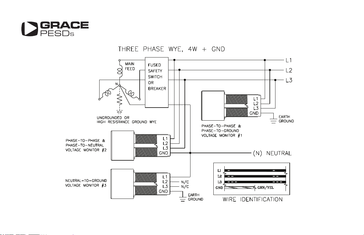
any two of the (4) terminal posts {L1, L2, L3, GND}.
1. To validate normal powered conditions, AC voltage is observed
for all six (6) post pair combination circuits {L1-L2, L1-L3, L2-L3,
L1-GND, L2-GND, L3-GND}.
2. To check for zero electrical energy during shut o, verify
sources of feedback or stored energy are rst neutralized. With
the meter and leads setup for VAC measurement, verify the (6)
post pair combination circuits above are de-energized. Change
voltmeter and test leads for VDC measurement. Again verify the
(6) post pair combination circuits are also de-energized for VDC
(stored energy).
3. Ensure your facility personnel are properly trained with the use
and limitations of these devices and properly update the “Point
of Connections” on your installation drawings.
MAINTENANCE
With power removed, free dust and particles from the front of the
label and dust cap with compressed air. Open the dust cap by
unscrewing the cap screw and free the dust and particles on the
inside of the cap and jack sockets with compressed air. Maintain a
clean label by gently wiping with a clean damp cloth while power
is removed. Cleaning while powered is not recommended.
BEFORE OPENING A PANEL, TURN POWER
OFF! SAFETY PROCEDURES STILL APPLY!
Before working on an electrical conductor, verify zero electrical energy
with proper voltage testing instrument and the proper procedure as per
NFPA 70E 120.1(5), 120.2 (F)(2)(f)(1-6), OSHA 1910.333(b)(2)(iv)(B).”
AVANT D’OUVRIR UN PANNEAU ÉLECTRIQUE, COUPER
L’ALIMENTATION! LES PROCÉDURES DE SÉCURITÉ S’APPLIQUENT
TOUJOURS! Avant d’eectuer des travaux sur un conducteur électrique,
vérier que le courant est coupé à l’aide d’un instrument de mesure de
tension approprié en suivant la procédure adéquate, selon les normes
de la NFPA (National Fire Protection Association) 70E 120.1(5), 120.2
(F)(2)(f)(1-6), de l’OSHA (Occupational Safety and Health Administration)
1910.333(b)(2)(iv)(B).
OPERATION INSTRUCTIONS