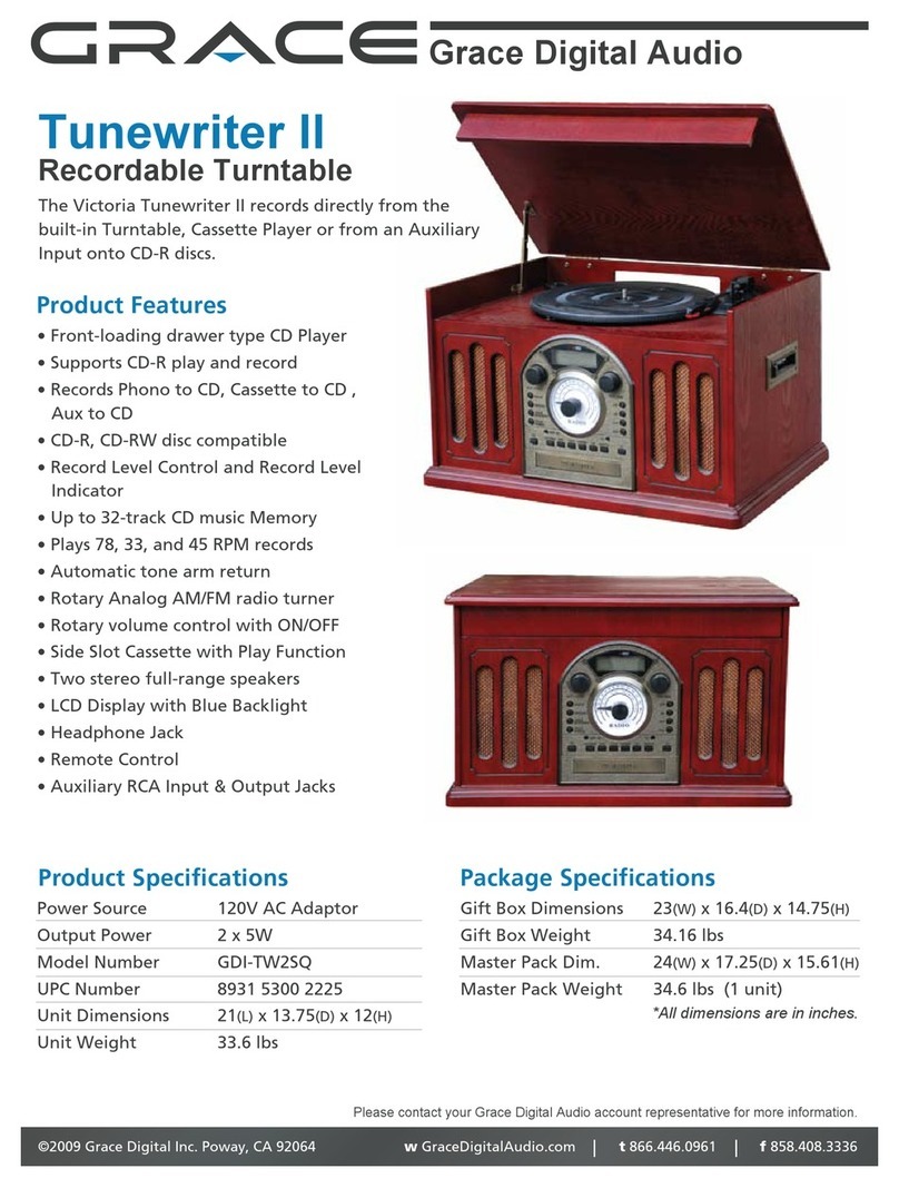
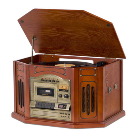
Grace Victoria GDI-TW4CD User manual


1
IMPORTANT SAFETY INSTRUCTION
PLEASE READ CAREFULLY ALL THE FOLLOWING IMPORTANT SAFEGUARDS
THAT ARE APPLICABLE TO YOUR EQUIPMENT
1 Read Instructions - All the safety and operating instructions should be read before the product is operated.
2 Retain instructions - The safety and operating instructions should be retained for future reference .
3 Heed Warnings - All warnings on the product and in the operating Instructions should be adhered to .
4 Follow Instructions -All operating and use instructions should be followed .
5 Cleaning -Unplug this product from the wall outlet before cleaning. Do no use liquid cleaners or aerosol cleaners.Use a damp
cloth for cleaning.
6 Attachments - Do not use attachments not recommended by the product manufacturer as they may cause hazards.
7 Water and Moisture - Do not use this product near water - for example,near a bath tub,wash bowl,kitchen sink,or laundry tub;
in a wet basement; or near a swimming pool;and the like .
8 A product and cart combination should be moved with care. Quick stops, excessive force, and uneven
surfaces may cause the product and cart combination to overturn.
9 Ventilation - Slots and openings in the cabinet are provided for ventilation and to ensure reliable
operation of the product and to protect it from overheating , and these openings must not be blocked or
covered ,The openings should never be blocked by placing the product on a bed ,sofa,rug, or other
similar surface . This product should not be placed in a built - in installation such as a bookcase or rack
unless proper ventilation is provided or the manufacturer's instructions have been adhered to .
10 Power Sources - This product should be operated only from the tape ofpower source indicated on the marking label, if
you are not sure of the type of power supply to your home. Consult your product dealer or local power company . For
products intended to operate from battery power, or other sources, refer to the operating instructions.
11 Grounding or Polarization -This product may be equipped with a polarizedalternating - current line plug (a plug having
one blade wider than the other). This plug will fit into the power outlet only one way. This is a safety feature. If you are
unable to insert the plug fully into the outlet try reversing the plug, if the plug should still
fail to fit, contact your electrician to replace your obsolete outlet. Do not defeat the safety purposeof the polarized plug.
12 Power - cord Protection -Power-supply cords should be routed so that they are not likely
to be walked on or pinched by items placed upon or against them,playing particular
attention to cords at plugs, convenience receptacles,and the point where they exit from the product.
13 Lightning-For added protection for this product during a lightning storm,or when it is left unattended
and unused for long periods of time, unplug it from the wall outlet and disconnect the antenna
or cable system. This will prevent damage to the product due to lightning and power-line surges.
14 Power Lines -An outside antenna system should not be located in the vicinity of overhead power lines or other
electric light or power circuits , or where it can fall into such power lines or circuits. When installing an outside antenna
system , extreme care should be taken to keep from touching such power lines or circuits as contact with them
might be fatal.
15 Overloading-Do not overload wall outlets, extension cords, or integral convenience receptacles as this can result in a risk
of fire or electric shock.
16 Object and Liquid Entry - Never push objects of any kind into this product through openings as they may touch dangerous
voltage points or short - out parts that could result in a fire or electric shock. Never spill liquid of any kind on
the
product.
17 Servicing - Do not attempt to service this product yourself as opening or removing covers may expose you to dangerous
voltage or other hazards. Refer all servicing to qualified service personnel.
18 Damage Requiring Service-Unplug this product from the wall outlet and refer servicing to qualified service personel under
the followin conditions
a. When the Power-supply cord or plug is damaged.
b. If liquid has been spilled, or objects have fallen into the product.
c. If the product has been exposed to rain or water.
d. If the product does not operate normally by following the operating structions. Adjust only those controls that are
covered by the operating instructions as an improper adjustment of other controls may result in damage and
will open require extensive work by a qualified technician to restore the product to its normal operation.
e. If the product has been dropped or damaged in any way.
f. When the product exhibits a distinct change in performance - this indicates a need for service.
19 Replacement Parts - When replacement parts are required, be sure the service technician has used replacement parts
specified by the manufacturer or have the same characteristics as the original part. Unauthorized substitutions may
result in fire, electric shock, or other hazards.
20 Safety Check - Upon completion of any service or repairs to this product,ask the service technician to perform safety
checks to determine that the product is in proper operating condition.
21 Wall or ceiling Mounting - The product should be mounted to a wall or ceiling only as recommended by the manufacturer.
22 Heat The product should be situated away from heat sources such as radiators. Heat registers, stoves, or other products
(including amplifiers)that produce heat.
WARNING:Changes or modifications to this unit not expressly approved by the party responsible for compliance could void the
user's authority to operate the equipment.
NOTE: This equipment has been tested and found to comply with the limits for a Class B digital device, pursuant to part 15 of
the FCC Rules. These limits are designed to provide reasonable protection against harmful interference in a residential
installation. This equipment generates, uses, and can radiate radio frequency energy and, if not installed and used in
accordance with the instructions, may cause harmful interference to radio communications. However, there is no guarantee
that interference will not occur in a particular installation. If this equipment does cause harmful interference to radio or
television reception, which can be determined by turning the equipment off and on, the user is encouraged to try to correct the
interference by one or more of the following measures:
- Reorient or relocate the receiving antenna.
- Increase the separation between the equipment and receiver.
- Connect the equipment into an circuit different from that to which the receiver is connected.
- Consult the dealer or an experienced radio TV technician for help.

2

3
Preparation for use
.................... 4
Unpacking&Set up
.................... 5
Location of Controls & Indicators 6-7
Operation Instruction 8-9
General
Radio Operation
(Antenna Information)
Turntable Operation
Cassette Operation
CD Operation
CD Recording Instruction 10-11
Preparation
Recording RECORDS to CD
Recording CASSETTES to CD
Manual track division
Erasing a CD-RW
Audio Connection 12
Aux In
Line Out
Specifications 13
Trouble Shooting Guide 14
Table of Contents
....................
....................
....................
....................
....................
Power Source
Accessories&Gift Box Contents
Warranty&Customer Support

TRANSIT SCREW
UNPACKING AND SET UP
Raise the lid The phonograph has been secured for shipment with a TRANSIT
SCREW. Use a coin or screwdriver to turn the transit screw clockwise
.
This will allow the turntable to “float”.
PREPARATION FOR USE
IMPORTANT : Raising And Lowering The Lid
To open the lid, raise it as far as it will go until the lid support bracket locks in
the open position .
To close the lid, lift it upward slightly until the lid support bracket unlocks, and
then gently lower the lid.
TO AVOID DAMAGING THE CABINET OR THE LID, NEVER FORCE THE
LID CLOSED. ALWAYS RAISE THE LID TO RELEASE THE LID SUPPORT
BRACKET.
4

STYLUS COVER
Discard the stylus cover.
Remove the twist -tie that was used to secure the tone arm during shipment.
Release the tone arm lock lever.
TONE ARM LOCK LEVER
Connect the plug to your AC outlet.
120V 60Hz
5
needle

N
I
N
U
G
T
RECORD
FINALI ZE
FF
FR
PLAY/PAUS E
STOP
OPEN/C LO SE
L
U
M
O
E
V
AUX
AM/FM
PHONO
CD
ERASE
AUTO MANUAL
TRACK IN CR EM EN T
ERAPHONE
POWER
TAPE
SENSOR
L
E
V
C
E
E
L
R
AUTO STOP
EJ
/
EF
1
2
3
4
5
6
7
8
9
10
11
12
13
14
15
16
17
18
19
20
21
22
24
2526
27
28
29 30
31
32
33
23
34
35
AUX IN
6
Mo./ST
CD RECORDER

LINE OUT
L
R
Unit Controls
LOCATION OF CONTROLS AND INDICATORS
36
37 38
REC
OP/CLOSE FUNTION
CD PHONO
AM/FM TAPE AUX
AUTO
MANUA L
++
__
INCREMENT REC LEVEL VOLUME
FINA LIZE
REPEAT
PROGRAM
PLAY/PAUSE
ERASE STOP
TRACK
REW FF
39
40
41
42
43
44
45
46
47
48
49
50
51
52
53
54
55
56
36 LINE OUT JACK
37 FM ANTENA WIRE
38 AC POWER CORD
39 OP/CLOSE
40 CD
41 PHONO
42 AM/FM
43 TAPE
44 AUX
45 AUTO MANUAL
46 INCREMENT TRACK
47 REC LEVEL “+” “-”
48 VOLUME “+” “-”
49 FINALIZE
50 REPEAT
51 PROGRAM
52 REW/FF
53 PLAY/PAUSE
54 ERASE
55 STOP
56 REC
7

General
Radio Operation
Antenna Information
Turntable operation
1 Make sure the unit is plugged in
correctly to an AC outlet.
2 Press the POWER(22) to turn on the
main power. Then you can press any
button you want.
1 Press the AM/FM button(4/42)to set
the unit to tuner mode.
2 Adjust the TUNING(12) to select a
station.
3 Adjust the VOLUME(2/48) to desired
listening level.
4 Press the Mo./ST (23) to select the
normal or stereo mode of Radio.
1 The AM antenna is inside the cabinet.
If AM reception is unsatisfactory try
repositioning the cabinet slightly until
the internal antenna is picking up the
strongest signal.
2 The FM wire antenna is located on the
back cabinet.If necessary adjust the
position and direction of this antenna
until you find the position that provides
the best reception.
1 Press the PHONO(6/41)to set the unit
to phono mode.
2 Make sure that you have removed the
stylus cover from the stylus and have
released the Tone Arm Lock that
secured the tone arm to the tone arm
rest.
3 Set the turntable Speed Selector to
t h e a p p r o p ri a t e s p e e d 3 3,4 5 o r 7 8
R P M . I f y o u a r e p l a y i n g 4 5 R P M
‘ s i n g l e s ',p l a c e t h e 4 5 R P M
ADAPTER(35) on the center spindle.
4 Place your record on the center
spindle.
5 Raise the CUE LEVER(30) to lift the
tone arm off its rest .Move the tone arm
to the edge of the record.The turntable
starts automatically .Use the CUE
LEVER (30)to gently lower the tone arm
onto the record.
6 Adjust the VOLUME(2/48) control to
the desired level.
7 When the tone arm reaches the end
of the record it automatically returns to
the tone arm rest and the record player
stops.
N O T E :D o no t st op the turntab le
m a n u a l l y M o v i n g o r j a r r i n g t h e
Turntable without securing the Tone
Arm clamp could result in damage to the
Tone Arm.
OPERATION INSTRUCTION
8

OPERATION OPERATION
CD OPERATION
1 Press the CD(7/40) button to set
the unit to CD mode.
2 Press the CD OPEN/CLOSE(19/39)
button to open the CD drawer.
3 Place your disc in the drawer with
the printed label side facing up.
4 Press the CD OPEN/CLOSE(19/39)
button once more to close the
drawer.The disc will spin for a few
seconds while the player reads the
disc ,then the disc stops and the
display shows the total number of
tracks on the disc.
5 Press the CD PLAY/PAUSE(17/53)
button to begin playback on track
number one . The Play Indicator lights.
6 Adjust the VOLUME(2/48) control to
the desired level.
7 Playback will continue until the
end of the dicc. When the disc ends
the display again shows the total
number of tracks on the disc. You
may also stop playback at any time
by pressing the CD STOP(18/55) button .
CASSETTE OPERATION
PLAYING CASSETTE
1 Press the TAPE(5/43) button to set
the unit to tape mode.
Note : Before inserting a tape in the
player be sure that there is no excess
slack in the cassette that could
jammed in the mechanism.
2 Insert your cassette into the
slot,as shown in the illustration,
with the side you wish to play
facing ' up' and the open end on
the right sde.
3 Cassette playback begins as
soon as the tape is inserted.Adjust
the VOLUME(2/48) control to the
desired level.
4 To advance the tape rapidly
depress the EJ/FF(26) (Eject/Fast
Forward) button approximately half
way.The tape will move forward
rapidly as long as the button is
depressed. Normal playback will
resume when the button is released.
5 When the tape ends the player
stops automatically.Depress the
E J /FF( 2 6 ) (E j e c t /F a s t F o r w a r d )
button completely to remove the
cassette from the player. You may
press theEJ/FF(26) ( Eject/Fast
Forward) button to stop playback
and remove the cassette at any
OPERATION INSTRUCTIONS
9

CD RECORDING INSTRUCTIONS
10
This unit is designed to record CD-R and
CD-RW discs bearing the identification
logo “Compact Disc Recordable” or “CD-
Rewritable”,If CD’s do not confirm to this
standard, they may not record properly.
Recording Records to CD
1 Load a compatible blank CD-R or CD-RW into the
unit.
2 Press the PHONO button (6/41) to set the unit to
Phono mode.
3 Set the SPEED CONTROL SWITCH (32) to the
correct speed (33 ,45 or 78 rpm) for the selected
record.
4 Use the CUE LEVER (30) to raise the tone arm off
its rest .Move the tone arm over the record and use
the cue lever to lower it to the point you want the
recording to start.
5 Press the RECORD button (13/56).Then press
“PLAY/PAUSE” button(17/53) .The CD will
begin recording.
6 Once the first side of the record is finished ,
press the STOP(18/55) button. The display will
change “PHONO”.
7 Turn the record over and repeat steps 4-6 to
record the other side.
8 After recording is completed, press the
STOP(18/55) button . The display then change to
“PHONO”.
9 Once you have finished the recording ,press the
CD button(7/40) then press FINALIZE button(14/49).
Then press PLAY/PAUSE(17/53) to finalize.
10 Once the CD has been finalized, the unit will
return to Phono mode and the display will show
“PHONO”. The CD door will open ,the CD is
now ready for use.
NOTE: If the CD is not finalized, it will not play in
any other CD player . Not all CD players are
compatible with CD-R and CD-RW ’s. Check the
owner's manual for other CD players for
compatibility.
Recording Cassettes to CD
1 Load a compatible blank CD-R or CD-
RW into the unit.
2 Press the TAPE button (5/43) to set the
unit to TAPE mode.
3 Load a pre-recorded cassette tape into
the cassette player. Press to PLAY
button(17/53) to get the cassette to the
point in which you want to start the
recording.
4 Once the cassette is ready and playing,
press the CD RECORD button (13/56) .
Then press “PLAY/PAUSE”(17/53) . The
CD will begin recording.
5 Once the first side of the cassette is
finished , press the STOP(18/55) button ,
then change to “TAPE”.
6 Eject the cassette tape and flip it over to
the other side.
7 Repeat steps 4 and 5 to record the other
side of the cassette .
8 After recording is completed,press the
STOP button(18/55),then change to“TAPE”.
9 Once you have finished the recording,
press the CD button(7/40), then press
“FINALIZE”button(14/49). Then press
PLAY/PAUSE (17/53) to finalize.
10 Once the CD has been finalized, the
unit will return to tape mode and the
display will show “TAPE” . The CD door
will open ,the CD is now ready for use.
NOTE: If the CD is not finalized. The
LCD will display "No TOC CD-R or CD-
RW. If the CD is finalized. The LCD will
display"CD-R or CD-RW.
Preparation

11

AUDIO CONNECTION
AUDIO CONNECTION
1 AUX IN
Press the AUX(3) button to set the unit
to Audio connection mode.
Using the Aux in allows you to hook up
additional external audio components
and listen to the m th rough you r
unit.Any component with an audio
output such as a Tuner , can be
c o n n e c t e d b y u s i n g t h e c o r r e c t
cables(not included).This unit uses
st an dard 3.5mm cables.For mo re
information on hooking up the external
component, see the owner's manual
for that component.
2 LINE OUT
Using the LINE OUT will allow you to
run the audio from your unit into a
home stereo ,television or other stereo
source. To make this connection,you
will need standard RCA cables.Plug
the red and white connectors on one
end of the cable into the red and white
Audio Output jacks on the back of the
unit. The other end of the cable will
plug into the LINE OUT jacks of your
selected component. For more
information on hooking up to the
ext ern al c ompo nen t , see t he
owner's manual for that component.
LINE OUT
L
R
Audio output
L
R
L
(WHITE JACK)
R
(RED JACK)
LINE OUT LINE OUT
12

/
13

WARRANTY & CUSTOMER SUPPORT
Congratulations on the purchase of your new Grace product. All Grace Digital products
purchased directly from Grace Digital or from a Grace Digital authorized dealer are supported
by a 1 year limited warranty.
Grace Digital Inc. guarantees this item for a period of 1 year from the original date of
purchase.
The product is guaranteed against original defects in materials, manufacture and
workmanship for 1 year from the date of purchase. The guarantee covers the replacement of
equipment that proves to be faulty as a result of manufacturing defect only. No liability shall be
accepted for faults arising from accident or misuse.
In the event your equipment requires warranty attention and/or service, please contact your
place of purchase, Grace Digital Inc. at www.gracedigitalaudio.com or a Grace Digital
authorized Dealer.
In the event a replacement is required and a replacement of the same model is not available
for any reason, Grace Digital Inc. reserves the right to replace items with similar equipment of
equivalent value.
Under this warranty, at the company's discretion, repair of any defect, replacement of the
failed component(s) without charge for parts or labor, is agreed. This warranty does not imply
any acceptance by Grace Digital, nor agents of Grace Digital for consequential loss or
damages related to a product. The warranty specifically excludes fair wear and tear, accident,
and misuse of unauthorized modification.
This warranty is applicable in the United States only and does not in any way limit the
customer's legal rights. Claims and enquiries under the warranty for Grace products purchased
outside the USA should be addressed to the local importers or distributors. If you have
reason to claim under the warranty please contact your Dealer (original place of
purchase) in the first instance. Please retain all original packaging materials for
possible future use. We suggest that you complete details of purchase now and keep this
information, along with your proof of purchase in a safe place for future reference.
CONDITIONS
1. This Warranty will be granted when the original invoice or sales receipt (with proof of date
of purchase, product type and dealer's name) is presented together with the defective product.
2. This guarantee will NOT reimburse for any loss nor cover damage that may result from
adaptations or adjustments, made to the product.
3. This guarantee does NOT include any of the following:
i. Maintenance and/or repair of parts due to normal wear and tear.
ii. Changes to or uses of the product outside of the intended use as described in the
instruction manual.
iii. Transportation costs, home service costs and all related risks and costs of transport.
4. Damage resulting from any of the following:
i. Misuse including use for a purpose other than intended, installation or use of the product in
a manner inconsistent with the technical or safety standards, improper or incorrect installation.
ii. Repair done by a non-authorized agent, establishment or individual.
iii. Accidents related to shipping with UPS, USPS or any other mailing or shipping agent.
iv. Accidents including lightening, water, fire, improper ventilation or any cause beyond the
control of Grace Digital Inc.
Should you have any questions regarding your product, warranty or Grace Digital Inc. please
contact your original place of purchase or Grace Digital Customer Service Monday to Friday at
customerservice@gracedigital.net
14

15
Troubleshooting Guide
In case of trouble with the unit, please look through this chart and see if you can solve the
problem by yourself before calling your dealer.
Problem Cause Solution
THE WHOLE UNIT
Power dose not come
on when the power
switch is pressed.
Unit is unplugged. Connect the unit to the AC
power supply.
No sound comes out
of the speakers.
The volume is turned
down (to MIN).
The input selector does
not match the playback
source.
Adjust the volume.
Re-select the desired
input source.
TAPE DECK
The tape dose not
move.
The cassette tape is not
inserted properly.
Insert the cassette tape
correctly.
No sound from tape. The tape heads are dirty. Clean the tape heads.
The sound is distorted
or faint.
The tape heads are dirty. Clean the tape heads.
TUNER UNIT
Cannot listen to any
s t a t i o n , o r s i g n a l
appears weak.
The station is not tuned-in
properly.
A TV set is being used
nearby and is interfering
with the radio reception.
P r o p e r l y t u n e - i n t h e
desired station. Turn-off
the interfering set TV.
The sound is distorted. The antenna is not
oriented properly. Re-orient the antenna until
reception improves.
CD PLAYER
CD stops immediately
after starting, or unit
p a u s e s o r s t o p s
during play.
T h e C D i s i n s e r t e d
upside down. The CD is
dusty or dirty or there is
condensation on the CD.
Insert the CD with the
printed side right-side up.
Carefully clean and dry the
CD.
No sound. The CD player is paused. Press the PLAY/PAUSE
button.
Specific CD is noisy ,or
p l a y b a c k s t o p s o r
skips.
The CD is scratched.
Damaged or warped.
The disc is is very dirty.
The CD should be
changed.
Carefully clean the CD.
Table of contents
Other Grace Turntable manuals

Grace
Grace victoria tunewriter III GDI-TW3USB User manual

Grace
Grace GDI-VW00 User manual

Grace
Grace Vinylwriter Boca GDI-VW03 User manual

Grace
Grace Retrowriter GDI-C2CDRW User manual

Grace
Grace Retrowriter GDI-C2CDRW User manual

Grace
Grace GDI-VW00 User manual

Grace
Grace AVPUSB01S User manual

Grace
Grace AVUSPB01 User manual

Grace
Grace AVPUSB01S Owner's manual

Grace
Grace GDI-VW00 User manual