Graco 1K Ultra-Lite 243482 Operation manual

AIR OPERATED, SINGLE COMPONENT DISPENSE VALVE
1K Ultra–Litet
For dispensing a wide variety of single component sealants and adhesives.
4000 psi (28 MPa, 276 bar) Maximum Fluid Working Pressure
120 psi (0.84 MPa, 8.4 bar) Maximum Air Inlet Pressure
See page 2 for Table of Contents
Part No. 965766
Stainless Steel Wetted Parts, Machine
Mount Valve
Part No. 965767
Aluminum Wetted Parts, Hand–held
Valve with internal air switch
Part No. 965768
Aluminum Wetted Parts, Hand–held
Valve with electric switch for remote
operation
Part No. 965786
Aluminum Wetted Parts, Automatic
Machine Mount Valve
Part No. 243482
Stainless Steel Wetted Parts,
Precision Swirl Orbiter Mounted with
Nozzle Accessory
Part No. 243666
Stainless Steel Wetted Parts,
PrecisionFloRControl Valve
Machine Mount Valve
Instructions–Parts List
308876K
Model 965768 shown
8370A
Important Safety Instructions
Read all warnings and instructions in this manual.
Save these instructions.

2 308876
Table of Contents
Warnings 2. . . . . . . . . . . . . . . . . . . . . . . . . . . . . . . . . . . . . .
Features 5. . . . . . . . . . . . . . . . . . . . . . . . . . . . . . . . . . . . . .
Installation 6. . . . . . . . . . . . . . . . . . . . . . . . . . . . . . . . . . . . .
Operation/Maintenance 8. . . . . . . . . . . . . . . . . . . . . . . . .
Troubleshooting 10. . . . . . . . . . . . . . . . . . . . . . . . . . . . . . .
Service 11. . . . . . . . . . . . . . . . . . . . . . . . . . . . . . . . . . . . . .
Parts 16. . . . . . . . . . . . . . . . . . . . . . . . . . . . . . . . . . . . . . . .
Accessories 25. . . . . . . . . . . . . . . . . . . . . . . . . . . . . . . . . .
Technical Data 27. . . . . . . . . . . . . . . . . . . . . . . . . . . . . . . .
Dimensions 28. . . . . . . . . . . . . . . . . . . . . . . . . . . . . . . . . . .
Graco Standard Warranty 30. . . . . . . . . . . . . . . . . . . . . .
Graco Information 30. . . . . . . . . . . . . . . . . . . . . . . . . . . . .
Symbols
Warning Symbol
WARNING
This symbol alerts you to the possibility of serious
injury or death if you do not follow the instructions.
Caution Symbol
CAUTION
This symbol alerts you to the possibility of damage to
or destruction of equipment if you do not follow the
instructions.
WARNING
SKIN INJECTION HAZARD
Spray from the valve, hose leaks, or ruptured components can inject fluid into your body and cause
extremely serious injury, including the need for amputation. Fluid splashed in the eyes or on the skin
can also cause serious injury.
DFluid injected into the skin might look like just a cut, but it is a serious injury. Get immediate surgi-
cal treatment.
DDo not point the valve at anyone or at any part of the body.
DDo not stop or deflect leaks with your hand, body, glove or rag.
DBe sure the valve trigger safety operates before dispensing.
DLock the valve trigger safety when you stop dispensing.
DIf the nozzle clogs while dispensing, fully release the trigger immediately.
DFollow the Pressure Relief Procedure on page 8 whenever you: are instructed to relieve pres-
sure; stop dispensing; clean, check, or service the equipment; and install or clean the nozzle.
DTighten all fluid connections before operating the equipment.
DCheck the hoses, tubes, and couplings daily. Replace worn, damaged, or loose parts immediately.
Permanently coupled hoses cannot be repaired; replace the entire hose.
DUse only Graco approved hoses. Do not remove any spring guard that is used to help protect the
hose from rupture caused by kinks or bends near the couplings.

3308876
WARNING
INSTRUCTIONS
EQUIPMENT MISUSE HAZARD
Equipment misuse can cause the equipment to rupture or malfunction and result in serious injury.
DThis equipment is for professional use only.
DRead all instruction manuals, tags, and labels before operating the equipment.
DUse the equipment only for its intended purpose. If you are uncertain about usage, call your Graco
distributor.
DDo not alter or modify this equipment. Use only genuine Graco parts and accessories.
DCheck equipment daily. Repair or replace worn or damaged parts immediately.
DDo not exceed the maximum working pressure stated on the equipment or in the Technical Data
for your equipment. Do not exceed the maximum working pressure of the lowest rated component
in your system.
DUse fluids and solvents which are compatible with the equipment wetted parts. Refer to the Tech-
nical Data section of all equipment manuals. Read the fluid and solvent manufacturer’s warnings.
DDo not use hoses to pull equipment.
DRoute hoses away from traffic areas, sharp edges, moving parts, and hot surfaces. Do not expose
Graco hoses to temperatures above 180_F (82_C) or below –40_F (–40_C).
DComply with all applicable local, state, and national fire, electrical, and safety regulations.
DNever use 1,1,1-trichloroethane, methylene chloride, other halogenated hydrocarbon solvents or
fluids containing such solvents in this equipment. Such use could result in a serious chemical
reaction, with the possibility of explosion, which could cause death, serious injury, and/or substan-
tial property damage.

4 308876
WARNING
FIRE AND EXPLOSION HAZARD
Improper grounding, poor ventilation, open flames or sparks can cause a hazardous condition and
result in a fire or explosion and serious injury.
DGround the equipment and the object being sprayed. Refer to Grounding on page 6.
DIf there is any static sparking or you feel an electric shock while using this equipment, stop dis-
pensing immediately. Do not use the equipment until you identify and correct the problem.
DProvide fresh air ventilation to avoid the buildup of flammable fumes from solvents or the fluid
being dispensed.
DKeep the dispense area free of debris, including solvent, rags, and gasoline.
DExtinguish all open flames or pilot lights in the dispense area.
DDo not smoke in the dispense area.
DDo not turn on or off any light switch in the dispense area while operating or if fumes are present.
DDo not operate a gasoline engine in the dispense area.
TOXIC FLUID HAZARD
Hazardous fluid or toxic fumes can cause serious injury or death if splashed in the eyes or on the skin,
inhaled, or swallowed.
DKnow the specific hazards of the fluid you are using.
DStore hazardous fluid in an approved container. Dispose of hazardous fluid according to all local,
state and national guidelines.
DAlways wear protective eyewear, gloves, clothing and respirator as recommended by the fluid and
solvent manufacturer.

5308876
Features
Fig. 1 8374
A
4 Control Configurations
1. 1/8 npt(f) ported manifold block
2. Direct solenoid mount with speed control
3. Handle kit with 4-way air valve
4. Handle kit with electric switch
Accessory flow control fittings
to adjust open/close speed.
Shaft is free to align
Aluminum or stainless wetted housings
Snuff back restrictor ring (13) is removable
for high flow applications.
Replaceable nylon bearings
Divorced air section
Hard chrome/stainless steel shaft
Urethane u-cup secondary seals
Self centering plastic bearing
Proven primary seals
Hardened stainless steel needles
Reversible carbide seat for severe duty
DAdjustable forward travel to reduce material surge when
valve opens
DSevere-Dutytneedle and seat for longer operating life
DLubricated packings for longer seal life
DLightweight construction reduces operator/machinery
fatigue
DCompact size for small X–Y tables, working areas, and
robots
DHandle kit provides easy conversion from automatic to
manual usage
DStainless steel housing to handle most materials
Travel adjustment (Model 965766,
965767, 965768, and 965786 only)
8374B

6 308876
Installation
NOTES:
DReference numbers and letters in parentheses in
the text refer to the callouts in the figures and
drawings.
DAccessories are available from your Graco
representative. If you supply your own accessories,
be sure they are adequately sized and
pressure-rated to meet the system’s requirements.
Grounding
WARNING
FIRE AND EXPLOSION HAZARD
To reduce the risk of fire, explosion, and
serious injury, proper electrical ground-
ing of every part of your system is es-
sential. Read the warning section Fire
and Explosion Hazard on page 4, and
follow the grounding instructions below.
The following grounding instructions are minimum
requirements for a basic dispensing system. Your
system may include other equipment or objects which
must be grounded. Check your local electrical code for
detailed grounding instructions for your area and type
of equipment. Your system must be connected to a
true-earth ground.
DPump: ground the pump by connecting ground wire
and clamp as described in your separate pump
instruction manual.
DAir compressors and hydraulic power supplies:
ground the equipment according to the
manufacturer’s recommendations.
DFluid hoses: use only grounded fluid hoses with a
maximum of 500 feet (150 m) combined hose
length to ensure grounding continuity. Check the
electrical resistance of your fluid hoses at least
once a week. If your hose does not have a tag on it
which specifies the maximum electrical resistance,
contact the hose supplier or manufacturer for the
maximum electrical resistance limits, replace the
hose immediately.
DDispensing valve: ground the valve by connecting it
to a properly grounded fluid hose and pump.
DFluid supply container: ground according to your
local code.
DFlammable liquids in the spray area: must be in
approved, grounded containers. Do not store more
than the quantity needed for one shift.
DAll solvent pails used when flushing: ground
according to local code. Use only metal pails, which
are conductive. Do not place the pail on a
non-conductive surface, such as paper or
cardboard, which interrupts the grounding
continuity.
DTo maintain grounding continuity when flushing or
relieving pressure, hold a metal part of the valve
firmly to the side of a grounded metal pail, then
trigger the valve.
How to Use the Valve Trigger Safety
WARNING
To prevent accidental triggering of the
gun and reduce the risk of a serious inju-
ry, including fluid injection or splashing in
the eyes or on the skin, lock the gun trigger safety
when you stop dispensing.
SKIN INJECTION HAZARD
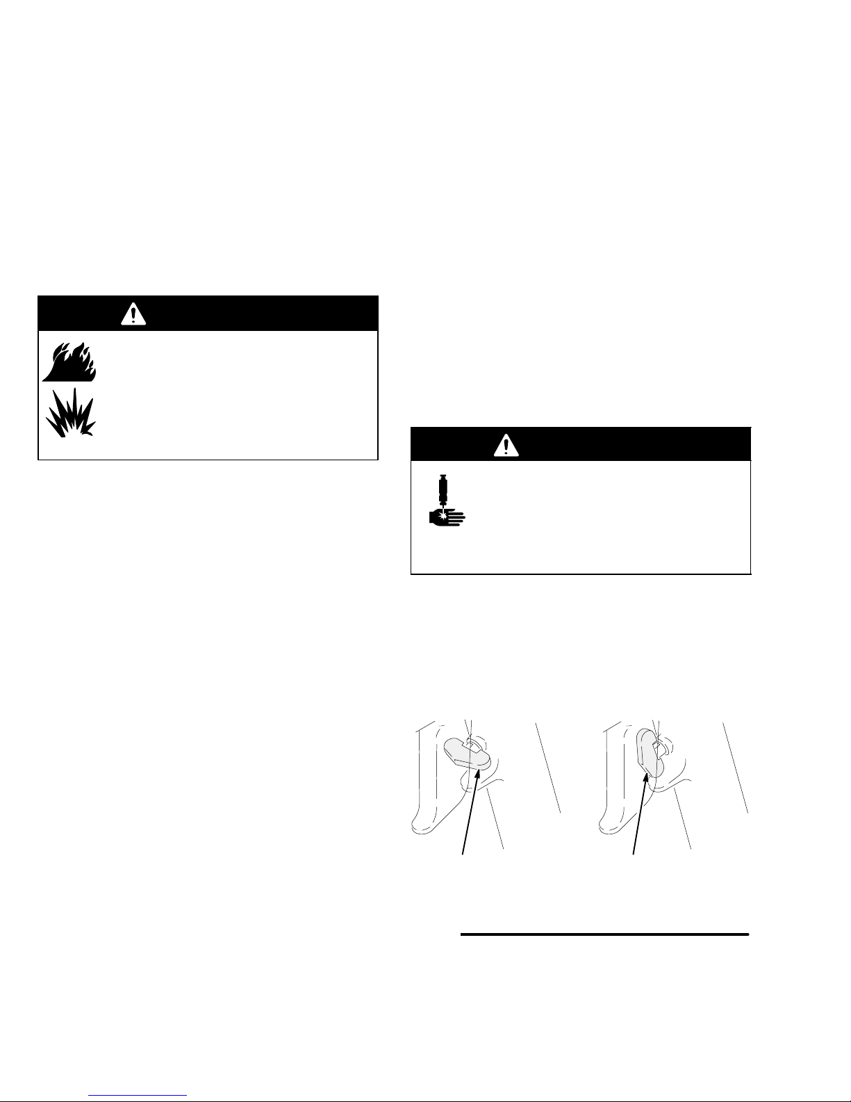
1. If you are using one of the hand-held versions of
the valve, lock the valve trigger safety by turning
the latch to a right angle with the gun body. See
Fig. 2.
2. To unlock the valve trigger safety, push the latch
out and turn it parallel with the gun body.
Fig. 2 8459
A
Locked Unlocked

7308876
Installation
Connections
DThe fluid inlet is 1/4 npt(f).
DThe fluid outlet is 1/4 npt(f) or 3/4–16 unf(m).
DAir inlets are 1/8 npt(f).
DSee Accessories, page 25, to order air control
valves and tubing.
Electric Switch Hand Held Valve
Install a remote 4-way air control valve to operate the
valve. Connect an OPEN air signal air line to the 1/8
npt(f) port on the side of the valve. Connect a CLOSE
air signal air line to the 1/8 npt(f) port on the opposite
side of the valve. Wire the normally open valve switch
to the system control.
Machine Mount Valve
Install a remote 4-way air control valve to operate the
valve. Connect an open air signal air line to the 1/8
npt(f) OPEN port. Connect a close air signal air line to
the 1/8 npt(f) CLOSE port.
Air Switch Hand Held Valve
This valve has a single air inlet and an internal 4-way
spool valve, which directly operates the air piston.
Connect the air line to the 1/8 npt(f) air inlet.
Fig. 3
1
3
2
8370A
1
2
3
Solder to terminals in cable connectors as shown in Detail A.
Normally open, momentary contact switch.
Ground connection.
Detail A
Electric Switch Hand Held Valve shown

8 308876
Operation
WARNING
COMPONENT RUPTURE HAZARD
To reduce the risk of over-pressurization,
which can cause component rupture and
serious injury, never exceed 3000 psi (21
MPa, 207 bar) fluid pressure, or 120 psi (0.84 MPa,
8.4 bar) air pressure to the valve.
Pressure Relief Procedure
WARNING
The system pressure must be manually
relieved to prevent the system from
starting or spraying accidentally. Fluid
under high pressure can be injected through the
skin and cause serious injury. To reduce the risk of
an injury from injection, splashing fluid, or moving
parts, follow the Pressure Relief Procedure
whenever you:
Dare instructed to relieve the pressure
Dstop dispensing
Dcheck or service any of the system equipment
Dinstall or clean the nozzle
SKIN INJECTION HAZARD
1. Shut off the air to the dispense valve, if applicable.
2. Shut off the air to the supply pumps.
3. Close the bleed-type master air valve (required in
your system).
4. Hold a metal part of the valve firmly to the side of a
grounded metal pail, and trigger the dispense
valve to relieve pressure.
5. Open the fluid drain valve (required in your
system), having a grounded metal container ready
to catch the drainage.
6. Leave the fluid drain valve open until you are ready
to dispense again.
If you suspect that the dispense needle or hose is
completely clogged, or that pressure has not been fully
relieved after following the steps above, very slowly
loosen the needle retaining nut or hose end coupling
and relieve pressure gradually, then loosen completely.
Now clear the needle or hose.
Electric Switch Hand Held Valve
DBe sure the air supply lines are connected correctly
to the OPEN and CLOSE valve air ports.
DTo open or close the valve and maintain the open or
closed status, a minimum of 40 psi (280 kPa, 2.8
bar) air pressure must be supplied and maintained
at the OPEN or CLOSE port.
DThe trigger only activates the electrical switch in the
handle, which turns the remote solenoid on and off.
DTrigger the gun to turn the solenoid on. Release the
trigger to turn the solenoid off.
Machine Mount Valve
DBe sure the air supply lines are connected correctly
to the OPEN and CLOSE valve air ports.
DTo open or close the valve and maintain the open or
closed status, a minimum of 40 psi (280 kPa, 2.8
bar) air pressure must be supplied and maintained
at the OPEN or CLOSE port.
To open the valve:
1. Apply air pressure to the OPEN air port on the
valve, and remove air pressure from the CLOSE
air port on the valve.
2. Maintain air pressure on the OPEN air port to keep
the valve open.
To close the valve:
1. Apply air pressure to the CLOSE air port on the
valve, and remove air pressure from the OPEN air
port on the valve.
2. Maintain air pressure to the CLOSE air port to
keep the valve closed.

9308876
Operation
Air Switch Hand Held Valve
The valve operation is such that there are only two
valve conditions: either fully open or fully closed.
The valve is opened and closed by the internal air
control valve. Trigger the gun to open the valve.
Release the trigger to close the valve.
Shaft Stroke Adjustment (Models 965766,
965767, 965768, and 965786 only)
Adjust the shaft stroke to balance the valve between
“snuff-back” and “push-out”.
DA long stroke will give maximum snuff-back but it
may cause push-out when the valve opens.
DShortening the stroke of the shaft will minimize the
material pushed out when the valve opens and will
also increase the material back pressure through
the valve.
To adjust the shaft stroke:
1. Loosen the hex nut (44) from the adjustment nut
(43).
2. Adjust the nut (44) along the adjustment shaft (42)
to the desired position.
DThe valve is at full stroke when the hex nut
(44) is at the end of the adjustment shaft (42).
DAdjusting the nut (44) on the shaft (42)
towards the valve, or clockwise, will reduce the
stroke length.
DAdjusting the nut away from the valve, or
counterclockwise, will lengthen the stroke.
3. Tighten the hex nut (44) to the adjustment nut (43)
to set the adjustment.
Fig. 4 8460
Shorten Lengthen
42 44
43
Maintenance
Preventative Maintenance
There is a grease filled secondary seal/bearing area on
the valve shaft. Every 10,000 cycles, or twice each
month, new grease should be flushed across this area.
Each valve has two flush grease fittings. A small
grease gun is provided with each valve.
To grease the valve:
1. Remove the grease fitting from one side of the
gun.
2. Pump grease (Part No. 115982) across the valve
until clear grease comes out of the other side.
3. Reinstall the grease fitting.

10 308876
Troubleshooting
WARNING
To reduce the risk of serious injury
whenever you are instructed to relieve
pressure, always follow the Pressure
Relief Procedure on page 8.
SKIN INJECTION HAZARD
1. Relieve the pressure.
2. Check all possible causes to the problem before
disassembling the pump.
PROBLEM CAUSE SOLUTION
Valve does not open Insufficient air pressure Turn on or turn up air pressure.
Air not exhausted from behind air cylin-
der piston Use four-way, relieving-type air valve operator.
Shaft adjustment too far closed Adjust the shaft stroke as instructed on page 9.
Valve does not close
(leaks) Insufficient air pressure Turn on or turn up air pressure.
Air not exhausted from behind air cylin-
der piston Use four-way, relieving-type air valve operator.
Blockage between needle and seat Remove and clean needle and seat.
Bad or missing gasket between seat
and housing Replace gasket (38).
Needle worn out Replace needle and seat.
Higher than normal
back-pressure Nosepiece plugging up Remove and clean.

11308876
Service
(Models 965766, 965767, 965768, and 965786 only)
WARNING
To reduce the risk of serious injury
whenever you are instructed to relieve
pressure, always follow the Pressure
Relief Procedure on page 8.
SKIN INJECTION HAZARD
Disassembly
1. Relieve all air and fluid pressure.
2. Disconnect the valve from the system.
3. Remove the four nosepiece screws (15), and pull
the nosepiece (40) away from the valve. Remove
the snuff-back ring (41). See Fig. 5, page 14.
4. Use an 1/8 in. pin punch in the needle hole (A) to
unscrew the needle (27). If the shaft (3) spins,
insert a dowel pin in the shaft hole (B) to hold it
steady, then unscrew the needle (27).
5. Remove the seat (25), gasket (38), and o-ring
(39).
6. Remove the two fluid housing screws (23) and
remove the fluid housing (26). Remove the primary
fluid seal (22) from the fluid housing (26).
7. Pull the bearing/lube housing (19) from the air
cylinder (1). Remove the bearing (21), bearing
o-ring (16), and secondary fluid seal (20). Remove
the grease fittings (18).
8. Remove the C-clip (12) from the back of the air
cylinder (1). Push the shaft (3) into the air cylinder
to dislodge the air cylinder cap (11). Remove the
cap o-ring.
9. Remove the internal C-clip (12). Push the shaft (3)
to dislodge the piston (10) assembly from the air
cylinder (1).
10. Remove the adjustment nut (44) from the shaft (3).
11. Remove the adjustment shaft (42) from the shaft
(3).
12. Remove the pin (7), o-ring (9), and piston o-ring
(6).
13. Use a 1/4 in. pin punch to knock out the bearings
(5) and o-rings (4).
Air Switch Handle (if equipped)
1. Remove the trigger (56).
2. Loosen the set screw above the trigger safety. Pull
off the handle (55).
3. Remove the four retaining screws (60). Pull the
housing (50) and gasket (30) away from the air
cylinder (1).
Air Valve
1. Unscrew the stem guide (58).
2. Remove the trigger pin (59), o-ring (57), spool
(49), spacers (51, 52), o-rings (46, 48) and spring
(47).
3. Remove the bushing (53) from the housing (50)
with the screw (54).
4. Remove the screws (60) and lock-washers (61)
from the air cylinder (1).
Electric Switch Handle (if equipped)
1. Disconnect the power from the gun.
2. The switch, housing, and cable are not repairable.
Replace these parts as a complete assembly.
3. Remove the trigger (56).
4. Loosen the setscrew above the trigger safety. Pull
off the handle (55).
5. Remove the four manifold retaining screws (60).
Pull the housing (50) and gasket (30) away from
the air cylinder (1).
6. Remove the bushing (53) from the housing (50)
with the screw (54).
7. Remove the screws (60) and lock-washers (61)
from the air cylinder (1).

12 308876
Service
(Models 965766, 965767, 965768, and 965786 only)
Reassembly
Air Cylinder Section
1. Lubricate the shaft o-rings (4) and the bearings (5)
with grease supplied in the repair kit. Insert o-rings
into the air cylinder (1) and air cap (11) cavities.
See Fig. 5.
2. Press the bearings (5) flush into the air cylinder
housing and air cap, trapping the o-rings (4).
3. Lubricate and reassemble the piston assembly;
piston (10), o-ring (9), dowel pin (7), adjustment
shaft (42), o-ring (6), and shaft (3). Use Loctiter
Primer N7649 and LoctiterTL242, 243, or
equivalent (“blue” Loctite) when assembling the
adjustment shaft (42). Tighten the shaft to 15–20
in–lb (1.7–2.2 NSm). The shaft (3) should hang
with some play to be self-aligning in the bearing.
4. Lubricate the air cylinder (1) ID with the grease
supplied. Push the piston (10) assembly into the
air cylinder.
5. Orient the air inlet manifold (2) (if used) as shown.
Match the gasket openings to the air ports.
Fluid Section
1. Lubricate the bearing (21), o-ring (16) and cup seal
(20). Put the o-ring (16) on the bearing. Carefully
insert the seal (20) into the bearing recess, with
the lips of the o-ring facing into the bearing. Be
careful not to damage the seal lips.
2. Push the bearing (21) seal end first into the
housing (19). Be sure that the grease hole in the
side of the bearing lines up with the grease ports in
the housing (19).
3. Holding the bearing (21) in place, push the bearing
assembly over the shaft (3).
4. Lubricate the main fluid seal (22) and its cavity in
the housing (26). Carefully press the seal, lip-first,
into the housing.
5. Push the housing (26) and seal (22) over the shaft
(3) and up against the bearing housing.
6. Apply anti–seize lubricant (Loctite 56765 or
equivalent) to the fluid housing screws (23) and
loosely install the screws to retain the housings.
Do not tighten the screws yet.
7. Insert the gasket (38) and seat (25). These items
are reversible and can be installed in either
direction.
8. Use Loctite Primer N7649 and Loctite TL242, 243,
or equivalent (“blue” Loctite) when assembling the
needle (27) and tighten to 15–20 in–lb (1.7–2.2
NSm).
9. Apply air pressure to the CLOSE port, or to the
pneumatic trigger valve if installed. This will align
the shaft, seal, and bearing. Tighten the fluid
housing screws (23) oppositely and evenly to
40–45 in-lbs (4.5–5 NSm).
10. Install the nosepiece (40) with the PTFE o-ring
(39), screw (15), and snuff-back ring (41), if used.
The snuff-back ring has an internal bevel on one
end which faces into the nosepiece. Tighten the
nosepiece screws to 15–20 in-lbs (1.7–2.2 NSm).

13308876
Service
(Models 965766, 965767, 965768, and 965786 only)
Air Valve (if equipped)
1. Insert the spring (51) into the housing (50).
2. Lubricate and install an o-ring (46) into the
housing.
3. Install a spacer (52), internal bevel first, into the
housing.
4. Lubricate and install two o-rings (46) and the
spacer (51).
5. Lubricate and install a spacer (52) with the internal
bevel out, and o-ring (46).
6. Lubricate and install o-rings (48) on the spool (49).
Insert the spool with the nub facing out.
7. Lubricate the pin (59) and insert it into the guide
(58). Screw the guide with o-ring (57) into the
housing. Tighten it to 60–70 in-lbs (6.8–7.9 NSm).
8. Orient the gasket (30) to the holes on the air
cylinder (1). Screw the air valve assembly to the
cylinder with the screws (60) and lock-washers
(61). TIghten the screws evenly to 15–20 in-lbs
(1.7–2.2 NSm).
9. Screw the bushing (53) to the housing (50) with
the screw (54). Tighten the screw to 140–150
in-lbs (15.8–16.9 NSm).
10. Attach the handle (55) with the setscrew.
11. Attach the trigger (56) with the grease fittings (18).
12. Test that the trigger safety works properly.
Electric Switch
1. The switch, housing, and cable are not repairable.
Replace these parts as a complete assembly.
2. The switch, housing, and cable assembly are not
user serviceable and must be replaced as an
assembly.

14 308876
Service
(Models 965766, 965767, 965768, and 965786 only)
8371A
2910 16
6 5 34 28, 29 20 21 22 39
41
23 40
38 25
27
Fig. 5
1
3
4
2
26
19 18
1
1211
30
56
61
60
53
54
55
4647 48 49
51 52
58 59
57 50
8370A
Tighten to 15–20 in-lb (1.7–2.2 NSm). The shaft should hang
with some play to be self-aligning in the bearing.
Tighten to 15–20 in-lbs (1.7–2.2 NSm).
Tighten oppositely and evenly to 40–45 in-lbs (4.5–5 NSm).
Lubricate with grease supplied in the repair kit.
Tighten to 60–70 in-lbs (6.8–7.9 NSm).
Screw the bushing (53) to the housing (50) with screw (54).
Tighten to 140–150 in-lbs (15.8–16.9 NSm).
Apply Loctite Primer N7649 and Loctite TL242, 243, or
equivalent (“blue” Loctite).
Apply anti–seize lubricant (Loctite 56765 or equivalent).
44
7
13, 14
1
2 3
5
5
4
6
2
6
4 4 4
44
4
44
44
4
4
44
4
4
42
4 4
8375B
7
7 8
8
7
15
B
A

15308876
Notes

16 308876
Parts
(Models 965766, 965767, 965768, and 965786 only)
8371A
1
19
18
26
30 12
2
(965766 &
965786 only)
9
10
16
11
7
6
5
3
4
28, 29
20
21
22
39
41
23
40
15
38
25
27
42
43
44
15

17308876
Parts
Model 965766
Machine Mount Valve
Stainless steel wetted parts
Model 965786
Automatic Machine Mount Valve
Aluminum wetted parts
Model 243482
Orbiter Mounted Valve
Stainless steel wetted parts
Model 243666
PrecisionFlo Control Valve
Stainless steel wetted parts
Ref.
No. Part No. Description Qty.
1 626702 HOUSING, air cylinder 1
2 626069 MANIFOLD, air control 1
3 626068 SHAFT, air cylinder 1
4* 156454 O-RING, 010 buna-n 2
5* 551181 BEARING, air cylinder 2
6* 154662 O-RING, 222 buna-n 2
7* 552164 DOWEL PIN 1
9* 157628 O-RING, 006 buna-n 1
10 626703 PISTON, air cylinder 1
11 626704 CAP, air cylinder CAP, air
cylinder; Models 965766
and 965786 only
1
196018 CAP, air cylinder; Models
243482 and 243666 only 1
12 552163 CLIP, internal 1.75 2
13 102817 SCREW, drive 2
14 552161 PLATE, identification 1
15 104371 SCREW, 10–32 x 0.375 4
16*† 103610 O-RING, 014
fluoroelastomer 1
18 551188 FLUSH GREASE FITTING 2
19 626705 LUBE HOUSING 1
20*† 551191 U-CUP, urethane/EPR 1
21* 626064 BEARING, lube 1
22*† 551190 U-CUP, Polymitet/EPR 1
23n103926 SCREW, 1/4–20 x 2.25 2
25* 185467 SEAT, C2 carbide 1
26 626731 HOUSING, fluid; stainless
steel; Model 965766 and
243282 only
1
626706 HOUSING, fluid; aluminum;
Model 965786 only 1
27*}626062 NEEDLE, hardened stain-
less steel 1
28Y188377 LABEL, skin injection haz-
ard 1
29Y188378 LABEL, read instruction
manual 1
Ref.
No. Part No. Description Qty.
30* 626057 GASKET, air cylinder 1
31 104459 SCREW, 10–32 x 1.75 4
35* 551186 GREASE, 3 oz. tube (not
shown) 1
36 115982 GUN, grease (not shown) 1
37 551187 COUPLER, flush grease
(not shown) 1
38*† 171860 GASKET, seat 1
39*† 104319 O-RING, 014 PTFE 1
40 626732 NOSEPIECE, stainless
steel; Models 965766 and
243666 only
1
626707 NOSEPIECE; aluminum;
Model 965786 only 1
195957 NOSEPIECE; stainless
steel; Model 243482 only 1
41* 626060 RING, snuff-back 1
42}626708 SHAFT, adjustment Models
965766 and 965786 only 1
43 626709 NUT, adjustment Models
965766 and 965786 only 1
44 100166 NUT, full hex, 10–32 Mod-
els 965766 and 965786 only 1
45 102920 NUT, jam, 10–32 Models
243482 and 2436666 only 1
* Included in Rebuild Kit 570268.
†Included in Section Seal Kit 570267.
YReplacement Instruction and Warning Labels are
available at not cost.
}Use Loctite Primer N7649 and Loctite TL242, 243,
or equivalent (“blue” Loctite) when assembling this
part.
nUse anti–seize lubricant (Loctite 56765 or
equivalent) when assembling 965766 and 965786.
Use Loctite TL242, 243, or equivalent (“blue”
Loctite) when assembling 243482 and 243666.

18 308876
Parts
8372A
8370A
63
46 48 49
51 52
58 59
57 50
(965768 only)
(965767 only)
47
8375B
61
60
53
54
55
56

19308876
Service
(Models 243482 and 243666 only)
WARNING
To reduce the risk of serious injury
whenever you are instructed to relieve
pressure, always follow the Pressure
Relief Procedure on page 8.
SKIN INJECTION HAZARD
Disassembly
1. Relieve all air and fluid pressure.
2. Disconnect the valve from the system.
3. Remove the four nosepiece screws (15), and pull
the nosepiece (40) away from the valve. Remove
the snuff-back ring (41). See Fig. 5, page 14.
4. Use an 1/8 in. pin punch in the needle hole (A) to
unscrew the needle (27). If the shaft (3) spins,
insert a dowel pin in the shaft hole (B) to hold it
steady, then unscrew the needle (27).
5. Remove the seat (25), gasket (38), and o-ring
(39).
6. Remove the two fluid housing screws (23) and
remove the fluid housing (26). Remove the primary
fluid seal (22) from the fluid housing (26).
7. Pull the bearing/lube housing (19) from the air
cylinder (1). Remove the bearing (21), bearing
o-ring (16), and secondary fluid seal (20). Remove
the grease fittings (18).
8. Remove the C-clip (12) from the back of the air
cylinder (1). Push the shaft (3) into the air cylinder
to dislodge the air cylinder cap (11). Remove the
cap o-ring.
9. Remove the internal C-clip (12). Push the shaft (3)
to dislodge the piston (10) assembly from the air
cylinder (1).
10. Remove the pin (7), o-ring (9), and piston o-ring
(6).
11. Use a 1/4 in. pin punch to knock out the bearings
(5) and o-rings (4).

20 308876
Service
(Models 243482 and 243666 only)
Reassembly
Air Cylinder Section
1. Lubricate the shaft o-rings (4) and the bearings (5)
with grease supplied in the repair kit. Insert o-rings
into the air cylinder (1) and air cap (11) cavities.
See Fig. 5.
2. Press the bearings (5) flush into the air cylinder
housing and air cap, trapping the o-rings (4).
3. Lubricate and reassemble the piston assembly;
piston (10), o-ring (9), dowel pin (7), o-ring (6), and
shaft (3). Tighten the jam nut (45) to 15–20 in-lb
(1.7–2.2 NSm). The shaft (3) should hang with
some play to be self-aligning in the bearing.
4. Lubricate the air cylinder (1) ID with the grease
supplied. Push the piston (10) assembly into the
air cylinder.
5. Orient the air inlet manifold (2) (if used) as shown.
Match the gasket openings to the air ports.
Fluid Section
1. Lubricate the bearing (21), o-ring (16) and cup seal
(20). Put the o-ring (16) on the bearing. Carefully
insert the seal (20) into the bearing recess, with
the lips of the o-ring facing into the bearing. Be
careful not to damage the seal lips.
2. Push the bearing (21) seal end first into the
housing (19). Be sure that the grease hole in the
side of the bearing lines up with the grease ports in
the housing (19).
3. Holding the bearing (21) in place, push the bearing
assembly over the shaft (3).
4. Lubricate the main fluid seal (22) and its cavity in
the housing (26). Carefully press the seal, lip-first,
into the housing.
5. Push the housing (26) and seal (22) over the shaft
(3) and up against the bearing housing.
6. Apply Loctite Primer N7649 and Loctite TL242,
243, or equivalent (“blue” Loctite) to the fluid
housing screws (23) and loosely install the screws
to retain the housings. Do not tighten the screws
yet.
7. Insert the gasket (38) and seat (25). These items
are reversible and can be installed in either
direction.
8. Apply Loctite Primer N7649 and Loctite TL242,
243, or equivalent (“blue” Loctite) to needle (27)
and tighten to 15–20 in–lb (1.7–2.2 NSm).
9. Apply air pressure to the CLOSE port, or to the
pneumatic trigger valve if installed. This will align
the shaft, seal, and bearing. Tighten the fluid
housing screws (23) oppositely and evenly to
40–45 in-lbs (4.5–5 NSm).
10. Install the nosepiece (40) with the PTFE o-ring
(39), screw (15), and snuff-back ring (41), if used.
The snuff-back ring has an internal bevel on one
end which faces into the nosepiece. Tighten the
nosepiece screws to 15–20 in-lbs (1.7–2.2 NSm).
This manual suits for next models
6
Table of contents
Other Graco Glue Gun manuals
Popular Glue Gun manuals by other brands

Stanley
Stanley FATMAX STHT6-70416 Original instructions

Parkside
Parkside PNKP 105 B1 Translation of the original instructions

Surebonder
Surebonder Hybrid-120 operating instructions

Ryobi
Ryobi R18GLU Original instructions

Clarke
Clarke CGG1C Instructions for use

EINHELL Bavaria
EINHELL Bavaria BKP 200 operating instructions