manuals.online logo
Brands
  1. Home
  2. •
  3. Brands
  4. •
  5. Graco
  6. •
  7. Heat Pump Accessories
  8. •
  9. Graco 222–687 Operation manual

Graco 222–687 Operation manual

INSTRUCTIONS-P
ARTS LIST
307–961
Rev
A
PUMP
P
ACKING KIT 222–687
For
Use In Displacement Pump 222–688
Pressure Relief Procedure
To
reduce
the risk of serious bodily injury
, includ
-
ing
fluid injection, splashing fluid or solvent in the
eyes
or on the skin, or injury from
moving parts or
electric shock, always follow this procedure
whenever you shut off the sprayer, when check-
ing or servicing any part of the spray system,
when installing, cleaning or changing spray tips,
and
whenever you stop spraying.
1.
Engage the gun safety latch.
2.
Turn the ON/OFF switch to OFF.
3.
Unplug the power supply cord.
4.
Disengage
the gun safety latch. Hold a
metal
part
of the gun firmly to the side of a grounded
metal
pail, and trigger the gun to relieve pres
-
sure.
5.
Engage the gun safety latch.
6. Open
the pressure drain valve, having a con
-
tainer
ready to catch the drainage. Leave the
valve
open until you are ready to spray
again.
If you suspect that the spray tip or hose is com-
pletely clogged, or that pressure has not been
fully
relieved after following the steps above,
wrap
a rag around the tip guard retaining nut or hose
end
coupling and VER
Y SLOWL
Y
loosen the part
to relieve pressure gradually, then loosen com-
pletely.
Now clear the tip or hose.
WARNING
1. Flush
the
pump, if possible. Follow the
Pressure
Relief
Procedure W
arning
, above.
2. Disassemble the pump. Clean and inspect all
parts for wear or damage and replace parts as
needed.
Coat the rod and the inside
of the cylin
-
der
with oil before reassembling.
NOTE: All
sprayers with DC/Brush-T
ype Motors:
When
replacing the pump packings, also in
-
spect the motor brushes and replace them,
if necessary.
3. Stack the backup washer (19), seal (5), female
gland (20), packings (17) and male gland (13)
onto
the piston valve (24).
T
ighten the
nut (B) onto
the
valve to 10.5 in–lb (1.2 N.m) to seat the
pack
-
ings,
and then back of
f and tighten finger tight.
Note
the alignment
of the
piston valve (D) to the
nut
(B) and maintain this alignment through Steps
3,
4 and 5. This helps ensure that the nut (B) does
not
overcompress and swell the packings, which
can
cause
them to be damaged when the piston
assembly
is installed in the cylinder
.
GRACO INC. P.O. BOX 1441
MINNEAPOLIS, MN
55440–1444
COPYRIGHT
1989, GRACO INC.
This
manual contains
IMPORTANT
INSTRUCTIONS and WARNINGS.
READ AND RETAIN FOR REFERENCE.
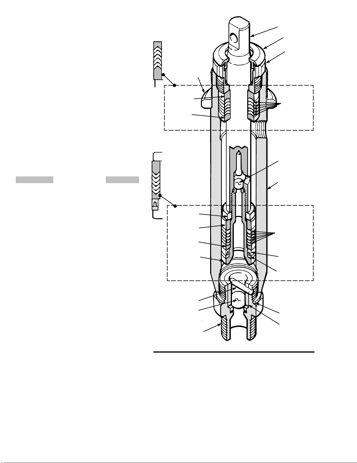
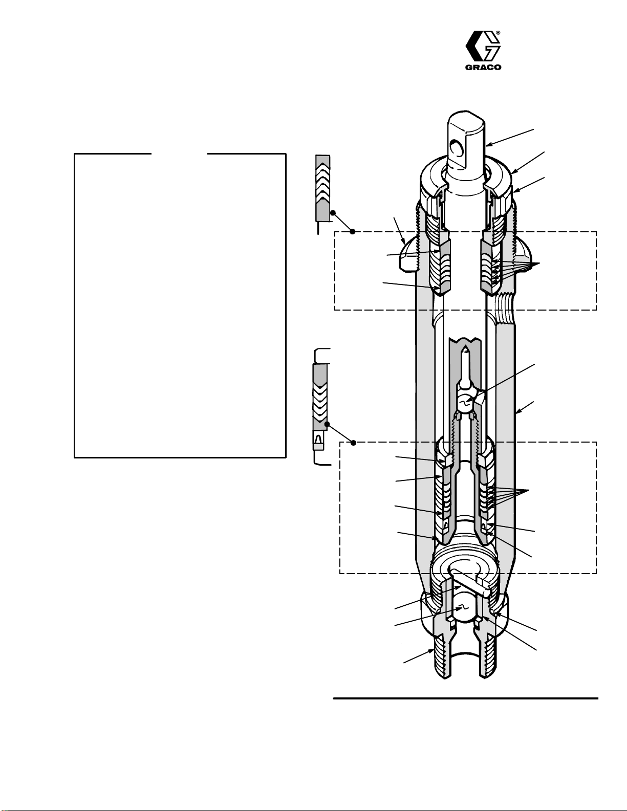
LIPS
OF
V–PACKING IN
THROAT MUST
FACE DOWN
DETAIL
OF
THROA
T P
ACKINGS
DET
AIL OF
PISTON PACKINGS
Fig
1
B
F
18
17
POLY
H
13
5
U-CUP SEAL
LIPS FACE DOWN
19
D
6
4
J
7
3
E
G
12
11
20
ROD
PACKING
NUT
JAM NUT
FEMALE
GLAND
MALE
GLAND
SMALL BALL
CYLINDER
PISTON NUT
MALE GLAND
BACKUP WASHER
GASKET
BALL GUIDE
LARGE BALL
PIN
PISTON
VALVE
FEMALE
GLAND
INTAKE VALVE
LIPS OF
V–PACKING IN
THROAT MUST
FACE DOWN
POLY
LIPS OF
V–PACKING IN
PISTON MUST
FACE UP
LIPS OF
V–PACKING IN
PISTON MUST
FACE UP
K
L
PLUG
4. Apply
one drop
of adhesive, supplied, on the
threads
of the piston valve. Place the small ball (3)
on the piston valve (D).
Hand tighten the valve
into
the rod (E) just until the nut contacts the rod.
Place
the flats of the rod in a vise
.
5. Tighten
the piston nut (B) onto the piston rod (E)
to 19 ft–lb (25 N.m). Use two wrenches to main-
tain the alignment as mentioned in Step
3,
page
1.
6. Stack
the male gland (1
1), packings
(18) and fe
-
male gland (12), one at a
time
into the top of the
cylinder
(H).
Install the packing nut (G) and plug
(L).
Leave the packing nut loose for now
.
7. Insert
the piston rod (23) through the
bottom
of the
oiled
pump cylinder
.
8. Assemble
the intake valve (J) with
a
new
gasket
(6), the large ball (4), ball guide (K), and pin (7).
Screw
the assembly into the pump cylinder
. T
ight-
en
to 80 ft-lb (109 N.m)
9. Install
the jam nut (F) on the
cylinder
, if it was re
-
moved. Connect
the pump to the sprayer as de
-
scribed in your separate pump instruction
manual.
10. Tighten the packing nut (G) just enough to stop
leakage, but no tighter. Fill the wet–cup/packing
nut
1/3 full with Graco TSL.
PARTS LIST
Repair
Kit 222–687
REF
NO.
P
ART NO.
DESCRIPTION QTY
3 105–444
BALL,
sst;
0.3125”
1
4 105–445 BALL,
sst;
0.50”
1
5 108–995 SEAL,
u–cup 1
6 176–761 GASKET
,
copper 1
7 176–759 PIN,
ball stop
1
11 183–556 GLAND,
male,
1
12 183–237 GLAND,
female, brass
1
13 183–236 GLAND,
male, brass
1
17 176–882 V–PACKING, polyethylene 5
18 176–997 V–PACKING,
polyethylene 5
19 183–557 WASHER, backup 1
20 183–558 GLAND,
packing, female
1
25 ADHESIVE 1
Factory
Branches:
Atlanta, Dallas, Detroit, Los Angeles, W
est Caldwell (N.J.)
Subsidiary and Affiliate Companies:
Canada; England; Switzerland; France; Germany; Hong Kong; Japan
GRACO INC. P
.O. BOX 1441
MINNEAPOLIS, MN
55440–1444
PRINTED IN U.S.A. 307–961
2–89
LIPS
OF
V–PACKING IN
THROAT MUST
FACE DOWN
DETAIL
OF
THROA
T P
ACKINGS
DET
AIL OF
PISTON PACKINGS
Fig
2
B
F
18
17
POLY
H
13
5
U-CUP SEAL
LIPS FACE DOWN
19
D
6
K
4
J
7
3
E
G
12
11
20
ROD
PACKING
NUT
JAM NUT
FEMALE
GLAND
MALE
GLAND
SMALL BALL
CYLINDER
PISTON NUT
MALE GLAND
BACKUP WASHER
GASKET
BALL GUIDE
LARGE BALL
PIN
PISTON
VALVE
FEMALE
GLAND
INTAKE VALVE
LIPS OF
V–PACKING IN
THROAT MUST
FACE DOWN
POLY
LIPS OF
V–PACKING IN
PISTON MUST
FACE UP
LIPS OF
V–PACKING IN
PISTON MUST
FACE UP
L
PLUG

Popular Heat Pump Accessories manuals by other brands

Vaillant VWZ MPS 40 installation instructions

Vaillant

Vaillant VWZ MPS 40 installation instructions

Nibe EF 45 Installer manual

Nibe

Nibe EF 45 Installer manual

Anslut 417-038 Assembly instructions

Anslut

Anslut 417-038 Assembly instructions

Lennox 61H42 installation instructions

Lennox

Lennox 61H42 installation instructions

Flow HyPlex Prime Minor installation guide

Flow

Flow HyPlex Prime Minor installation guide

manuals.online logo
manuals.online logoBrands
  • About & Mission
  • Contact us
  • Privacy Policy
  • Terms and Conditions

Copyright 2025 Manuals.Online. All Rights Reserved.